Kichler Lighting 44206PN Manuel utilisateur
- Taper
- Manuel utilisateur

Date Issued: 10/09/17
IS-44206-CB
We’re here to help 866-558-5706
Hrs: M-F 9am to 5pm EST
CAUTION – RISK OF SHOCK –
Disconnect Power at the main circuit breaker panel or main
fusebox before starting and during the installation.
14
15
16
►
►
10
8
1
2
3
4
5
6
7
9
11
12
13
14
15
16
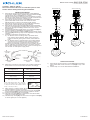
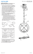
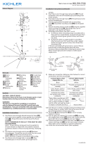
RIGID STEM MOUNT
SEMI-FLUSH MOUNT
4
5
12
13
6
7
10
8
9
11
3
14
15
16
►
►
10
8
1
2
3
4
5
6
7
9
11
12
13
14
15
16
RIGID STEM MOUNT
SEMI-FLUSH MOUNT
4
5
12
13
6
7
10
8
9
11
3
SWIVEL/STEM MOUNT
1) Pass xture wire through desired amount of stems[1] and
screw stems together using supplied short threaded tubes[2].
Thread stems into coupler[3] on top of xture.
NOTE: Thread locking compound must be applied to all stem
threads as noted with arrow symbol to prevent accidental rota-
tion of xture during cleaning, relamping, etc.
2) Pass xture wire through end of swivel[4] without threaded
pipe. Thread that end of swivel onto end of last stem.
NOTE: Direction of swivel in accordance with ceiling.
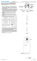
3) Pass xture wire through hole in canopy[5]. Pass threaded
pipe on end of swivel up through hole in canopy.
4) Pass xture wire through lockwasher[6]. Thread lockwasher
onto end of threaded pipe protruding from inside canopy. Pass
xture wire through hexnut[7]. Thread hexnut onto end of
threaded pipe.
5) Find the appropriate threaded holes on mounting strap[8]. As-
semble mounting screws[9] into threaded holes.
6) Attach mounting strap to outlet box[10] using the strap mount-
ing screws[11]. Mounting strap can be adjusted to suit position
of xture.
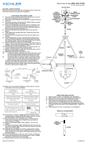
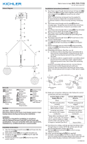
7) Grounding instructions: (See Illus. A or B).
A) On xtures where mounting strap is provided with a
hole and two raised dimples. Wrap ground wire from
outlet box around green ground screw, and thread into
hole.
B) On xtures where a cupped washer is provided. Attach
ground wire from outlet box under cupped washer and
green ground screw, and thread into mounting strap.
If xture is provided with ground wire. Connect xture ground
wire to outlet box ground wire with wire connector. (Not pro-
vided.) After following the above steps. Never connect ground
wire to black or white power supply wires.
8) Make wire connections (connectors not provided.) Reference
chart below for correct connections and wire accordingly.
9) Raise canopy to ceiling. NOTE: Be certain wires do not get
pinched between canopy and ceiling.
10) Secure canopy in place by using the use lock-up knobs[12]
and lockwashers[13] to secure canopy. Tighten to secure.
11) Insert recommended bulb (not supplied).
12) Carefully raise glass[14] up to the xture. Pass the smaller
opening over the bulb and socket.
13) Thread lockup knobs[15] into the holes in the glass holder[16]
to secure glass (do not over-tighten ).
GREEN GROUND
SCREW
CUPPED
WASHER
OUTLET BOX
GROUND
FIXTURE
GROUND
DIMPLES
WIRE CONNECTOR
OUTLET BOX
GROUND
GREEN GROUND
SCREW
FIXTURE
GROUND
A
B
Connect Black or
Red Supply Wire to:
Connect
White Supply Wire to:
Black White
*Parallel cord (round & smooth) *Parallel cord (square & ridged)
Clear, Brown, Gold or Black
without tracer
Clear, Brown, Gold or Black
with tracer
Insulated wire (other than green)
with copper conductor
Insulated wire (other than green)
with silver conductor
*Note: When parallel wires (SPT I & SPT II)
are used. The neutral wire is square shaped
or ridged and the other wire will be round in
shape or smooth (see illus.)
Neutral Wire
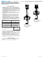
SEMI-FLUSH MOUNT
1) Pass xture wire through end of swivel[4] without threaded
pipe. Thread that end of swivel into coupler[3] on top of the
xture.
2) Follow steps 3-13 on the Swivel/Stem Installation.

Date Issued: 10/09/17
IS-44206-CB
INSTRUCTIONS
For Assembling and Installing Fixtures in Canada
Pour L’assemblage et L’installation Au Canada
Nous sommes là pour vous aider 866-558-5706
Heures : du lundi au vendredi, de 9h à 17h (heure de l’Est)
ATTENTION – RISQUE DE DÉCHARGES ÉLECTRIQUES -
Couper le courant au niveau du panneau du disjoncteur du
circuit principal ou de la boîte à fusibles principale avant de
procéder à l’installation.
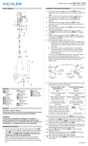
SWIVEL/STEM MOUNT
1) Passer le l de xation à travers la quantité souhaitée de
tiges[1] et la visdérive en utilisant des tubes à letage court
fournis[2]. Le letage tombe dans le coupleur [3] au-dessus du
luminaire. REMARQUE: le composé de verrouillage de letage
doit être appliqué à tous les ls de la tige comme indiqué avec
un symbole éché pour empêcher la rotation accidentelle du
luminaire pendant le nettoyage, la relamping, etc.
2) Passer le l de xation à travers l’extrémité de pivotement sans
tuyau leté[4]. Enlez l’extrémité de pivotement sur l’extrémité
de la dernière tige.
NOTE pivotante en conformité avec le plafond.
3) Faire passer le l de xation à travers le trou dans la cano-
pée[5]. Passez tuyau leté sur l’extrémité de pivot dans le trou
de la canopée.
4) Faire passer le l de xation dans le trou de la rondelle
d’arrêt[6]. Enler la rondelle d’arrêt sur l’extrémité du tuyau
leté faisant saillie à l’intérieur de la canopée.Faire passer
le l de xation dans le trou du hexnut[7]. Enlez hexnut sur
l’extrémité du tuyau leté.
5) Trouvez les trous taraudés appropriés sur sangle de xa-
tion[8]. Monter les vis de montage dans les trous letés[9].
6) Attachez la sangle de xation à la boîte de sortie[10] en util-
isant les vis de xation de la sangle[11]. sangle de xation peut
être ajustée en fonction de la position de montage.
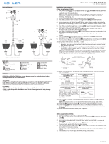
7) Connecter les ls. Se porter au tableau ci-dessous pour faire
les connexions.
8) Soulever la verrière au plafond. REMARQUE : Vous assurer
que tous les ls sont dans le couvercle et ne se retrouvent pas
pincés entre le couvercle et le plafond.
9) Fixez la verrière en place en utilisant les boutons de verrouil-
lage [12] et les dispositifs de verrouillage [13] pour sécuriser le
voile. Serrez pour sécuriser.
10) Installer la ou les ampoules recommandées (non fournies).
11) Soulevez soigneusement le verre [14] jusqu’à l’appareil. Pas-
sez l’ouverture plus petite sur l’ampoule et la prise.
12) Permet de verrouiller les boutons de verrouillage [15] dans les
trous du support de verre [16] pour sécuriser le verre (ne pas
trop serrer).
SEMI-FLUSH MOUNT
1) Pass xture wire through end of swivel[4] without threaded
pipe. Thread that end of swivel into coupler[3] on top of the
xture.
2) Follow steps 3-13 on the Swivel/Stem Installation.
Connecter le fil noir ou
rouge de la boite
Connecter le fil blanc de la boîte
A Noir A Blanc
*Au cordon parallèle (rond et lisse)
*Au cordon parallele (à angles droits el strié)
Au bransparent, doré, marron, ou
noir sans fil distinctif
Au transparent, doré, marron, ou
noir avec un til distinctif
Fil isolé (sauf fil vert) avec
conducteur en cuivre
Fil isolé (sauf fil vert) avec
conducteur en argent
*Remarque: Avec emploi d’un fil paralléle
(SPT I et SPT II). Le fil neutre est á angles
droits ou strié et l’autre fil doit étre rond ou
lisse (Voir le schéma).
Fil Neutre
14
15
16
►
►
10
8
1
2
3
4
5
6
7
9
11
12
13
14
15
16
RIGID STEM MOUNT
SEMI-FLUSH MOUNT
4
5
12
13
6
7
10
8
9
11
3
14
15
16
►
►
10
8
1
2
3
4
5
6
7
9
11
12
13
14
15
16
RIGID STEM MOUNT
SEMI-FLUSH MOUNT
4
5
12
13
6
7
10
8
9
11
3
-
 1
1
-
 2
2


Kichler Lighting 44206PN Manuel utilisateur
- Taper
- Manuel utilisateur
dans d''autres langues
- English: Kichler Lighting 44206PN User manual
Documents connexes
-
 Kichler Lighting 43996CH Manuel utilisateur
-
 Kichler Lighting 42592OZ Manuel utilisateur
-
 Kichler Lighting 44201PN Manuel utilisateur
-
 Kichler Lighting 44268PN Manuel utilisateur
-
 Kichler Lighting 44286WWW Manuel utilisateur
-
Kichler 43696BK Manuel utilisateur
-
 Kichler Lighting 52268BK Manuel utilisateur
-
Kichler Lighting 44275PN Manuel utilisateur
-
 Kichler Lighting 44276PN Manuel utilisateur
-
Kichler Lighting 44169BK Manuel utilisateur


