Tweco Robotics QWT-120 Wire Cutting Station Guide d'installation
- Taper
- Guide d'installation

50
60
Hz
1
PHASE
GTAW
SMAW
INVERTER
CC
DC
115
V
230
V
WIRE CUTTING
STATION
Installation and Operation
Guide
English
Français
Español
QWT-120
Revision No: A Issue Date: November 12, 2008 Manual No: SM-QWT-120

50
60
Hz
1
PHASE
GTAW
SMAW
INVERTER
CC
DC
115
V
230
V
Congratulations on your new Tweco
®
Robotics product. We are proud
to have you as our customer and will strive to provide you with the
best service and reliability in the industry. This product is backed by
our extensive warranty and world-wide service network. To locate your
nearest distributor or service agency, please contact a representative at
the address and phone number in your area listed on the inside back
cover of this manual, or visit us on the web at www.tweco.com.
This Operating Manual has been designed to instruct you on the correct
use and operation of your Tweco
®
Robotics product. Your satisfaction
with this product and its safe operation is our ultimate concern.
Therefore, please take the time to read the entire manual, especially the
Safety Precautions. They will help you to avoid potential hazards that
may exist when working with this product.
YOU ARE IN GOOD COMPANY!
The Brand of Choice for Contractors and Fabricators Worldwide.
Tweco
®
Robotics is a Global Brand of Arc Welding Products for
Thermadyne Industries Inc. We manufacture and supply to major
welding industry sectors worldwide including; Manufacturing,
Construction, Mining, Automotive, Aerospace, Engineering, Rural and
DIY/Hobbyist.
We distinguish ourselves from our competition through market-leading,
dependable products that have stood the test of time. We pride ourselves
on technical innovation, competitive prices, excellent delivery, superior
customer service and technical support, together with excellence in
sales and marketing expertise.
Above all, we are committed to develop technologically advanced
products to achieve a safer working environment within the welding
industry.
WE APPRECIATE YOUR BUSINESS!

WARNING
READ AND UNDERSTAND THIS ENTIRE MANUAL AND YOUR EMPLOYER’S SAFETY PRACTICES BEFORE INSTALLING,
OPERATING, OR SERVICING THE EQUIPMENT.
WHILE THE INFORMATION CONTAINED IN THIS MANUAL REPRESENTS THE MANUFACTURER’S BEST JUDGMENT, THE
MANUFACTURER ASSUMES NO LIABILITY FOR ITS USE.
Wire Cutting Station
Installation and Operation Guide
Instruction Manual Number SM-QWT-120
Published by:
Tweco
®
Products Inc.
2800 Airport Road
Denton, TX 76208
(940) 566-2000
www.tweco.com
Copyright © 2008 by
Thermadyne Industries Inc.
® All rights reserved.
Reproduction of this work, in whole or in part, without written permission of the publisher is prohibited.
The publisher does not assume and hereby disclaims any liability to any party for any loss or damage caused by any
error or omission in this Manual, whether such error results from negligence, accident, or any other cause.
Publication Date: November 12, 2008
Record the following information for Warranty purposes:
Where Purchased: ________________________
Purchase Date: ________________________
Equipment Serial #: ________________________
i

wire cutting station
ii
SM-QWT-120
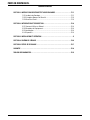
Table of Contents
SECTION 1: SAFETY INSTRUCTIONS AND WARNINGS .......................................... 1-1
1.01 Welding Hazards .......................................................................................1-1
1.02 Principal Safety Standards ........................................................................1-3
1.03 Safety and Health ......................................................................................1-3
SECTION 2: INTRODUCTION AND DESCRIPTION ................................................. 2-4
2.01 How to Use this Manual ............................................................................2-4
2.02 Receipt of Equipment ................................................................................2-4
2.03 Introduction ..............................................................................................2-4
2.04 Features ....................................................................................................2-4
SECTION 3: INSTALLATION AND OPERATION .....................................................
3-5
SECTION 4: WIRING DIAGRAM ......................................................................
4-6
SECTION 5: REPLACEMENT PARTS .................................................................
5-7
SECTION 6: FACTORY REPAIR CENTER ............................................................ 6-8
LIMITED WARRANTY .................................................................................
6-9

wire cutting station
1-1
SM-QWT-120
SAFETY INSTRUCTIONS AND WARNINGS
SECTION 1:
SAFETY INSTRUCTIONS AND WARNINGS
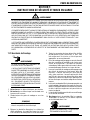
WARNING
SERIOUS INJURY OR DEATH MAY RESULT IF WELDING AND CUTTING EQUIPMENT IS NOT PROPERLY INSTALLED,
USED AND MAINTAINED. MISUSE OF THIS EQUIPMENT AND OTHER UNSAFE PRACTICES CAN BE HAZARDOUS. THE
OPERATOR, SUPERVISOR, AND HELPER MUST READ AND UNDERSTAND THE FOLLOWING SAFETY WARNINGS AND
INSTRUCTIONS BEFORE INSTALLING OR USING ANY WELDING OR CUTTING EQUIPMENT.
THE WELDING AND CUTTING PROCESS IS USED IN MANY POTENTIALLY DANGEROUS ENVIRONMENTS SUCH
AS ELEVATED HEIGHTS, AREAS OF LIMITED VENTILATION, CLOSE QUARTERS, AROUND WATER, IN HOSTILE
ENVIRONMENTS, ETC., AND IT IS IMPORTANT THAT THE OPERATOR(S) ARE AWARE OF THE DANGERS ASSOCIATED
WITH WORKING IN THESE TYPES OF CONDITIONS. BE CERTAIN THAT THE OPERATOR(S) ARE TRAINED IN
SAFE PRACTICES FOR ENVIRONMENTS IN WHICH THEY ARE EXPECTED TO WORK AND UNDER COMPETENT
SUPERVISION.
IT IS ESSENTIAL THAT THE OPERATOR, SUPERVISOR AND ALL OTHER PERSONNEL IN THE WORK AREA ARE AWARE
OF THE DANGERS OF THE WELDING OR CUTTING PROCESS. TRAINING AND PROPER SUPERVISION ARE IMPORTANT
FOR A SAFE WORK PLACE. KEEP THESE INSTRUCTIONS FOR FUTURE USE. ADDITIONAL RECOMMENDED SAFETY
AND OPERATING INFORMATION IS REFERENCED IN EACH SECTION.
5. All ground connections must be checked periodically
to determine that they are mechanically strong and
electrically adequate for the required current.
6. When engaged in alternating current, welding, or
cutting under wet conditions or warm surroundings
where perspiration is a factor, the use of reliable
automatic controls for reducing the no-load voltage
is recommended to reduce shock hazard.
7. When the welding or cutting process requires values of
open circuit voltages in alternating current machines
higher than 80 volts, and direct current machines
higher than 100 volts, means must be provided to
prevent the operator from making accidental contact
with the high voltage by adequate insulation or other
means.
8. When welding is to be suspended for any substantial
length of time, such as during lunch or overnight,
all electrodes should be removed from the electrode
holder and the electrode holder carefully located so
that accidental contact cannot occur.
9. The holder must be disconnected from the power
source when not in use.
10.
Never immerse Mig-Guns, electrode holders, tig
torches, plasma torches, or electrodes in water.
WARNING
SMOKE, FUMES, AND GASES CAN BE DANGEROUS
TO YOUR HEALTH.
1.01 Welding Hazards
WARNING
ELECTRIC SHOCK CAN CAUSE INJURY OR DEATH.
INSTALL AND MAINTAIN EQUIPMENT IN ACCORDANCE
WITH THE NATIONAL ELECTRICAL CODE (NFPA 70)
AND LOCAL CODES. DO NOT SERVICE OR REPAIR
EQUIPMENT WITH POWER ON. DO NOT OPERATE
EQUIPMENT WITH PROTECTIVE INSULATORS
OR COVERS REMOVED. SERVICE OR REPAIR TO
EQUIPMENT MUST BE DONE BY A QUALIFIED REPAIR
TECHNICIAN, OR TRAINED PERSONNEL ONLY.
1. Do not touch live electrical parts.
2.
Do not touch an electrode with bare skin and electrical
ground at the same time.
3. Always keep welding gloves dry and in good
condition.
NOTE
Aluminized protective clothing can become
part of the electrical path.
4. Keep oxygen cylinders, chains, wire ropes, cranes,
hoists, and elevators away from any part of the
electrical path.

wire cutting station
1-2
SM-QWT-120
SAFETY INSTRUCTIONS AND WARNINGS
21. Flammable hair preparations should not be used when
welding or cutting. Wear ear plugs to protect ears from
sparks.
22. Where the work area permits, the operator should be
enclosed in an individual booth painted with a finish of
low reflectivity such as zinc oxide. This is an important
factor for absorbing ultraviolet radiations, and lamp black.
The operator should be enclosed with non-combustible
screens similarly painted.
WARNING
WELDING SPARKS CAN CAUSE FIRES AND
EXPLOSIONS.
23. Causes of fire and explosion are: combustibles reached by
the arc, flame, flying sparks, hot slag, or heated material.
Remove combustibles from the work area and/or provide
a fire watch.
24
. Avoid oily or greasy clothing as sparks may ignite them. Have
a fire extinguisher nearby, and know how to use it.
25.
Be alert to the danger of conduction or radiation. For
example, if welding or cutting is to be done on a metal
wall, partition, ceiling, or roof, precautions must be taken
to prevent ignition of combustibles on the other side.
26. Do not w
eld or cut containers that have held combustibles.
All hollow spaces, cavities and containers should be vented
prior to welding or cutting to permit the escape of air or
gases. Purging with inert gas is recommended.
27.
Never use oxygen in a welding torch. Use only inert
gases or inert gas mixes as required by the process. Use
of combustible compressed gases can cause explosions
resulting in personal injury or death. Arcing against any
compressed gas cylinder can cause cylinder damage or
explosion.
WARNING
NOISE CAN DAMAGE HEARING.
28. Noise from the air carbon-arc process can damage
your hearing. Wear protective hearing devices to ensure
protection when noise levels exceed OSHA standards.
Adequate hearing protection devices must be worn by
operators and surrounding personnel to ensure personal
protection against noise.
11. Keep smoke, fumes, and gases from the breathing area.
12. Fumes from the welding or cutting process are of various
types and strengths, depending on the kind of base metal
being worked on. To ensure your safety, do not breathe
these fumes.
13. Ventilation must be adequate to remove smoke, fumes,
and gases during the operation to protect operators and
other personnel in the area.
14. Vapors of chlorinated solvents can form the toxic gas
“Phosgene” when exposed to ultraviolet radiation from an
electric arc. All solvents, degreasers, and potential sources
of these vapors must be removed from the work area.
15. Fumes produced by welding or cutting, particularly in
confined places, can cause discomfort and physical harm
if inhaled over an extended period of time.
16. Provide adequate ventilation in the welding or cutting area.
Use air-supplied respirators if ventilation is not adequate to
remove all fumes and gases. Never ventilate with oxygen.
Oxygen supports and vigorously accelerates fire.
WARNING
ARC RAYS, HOT SLAG, AND SPARKS CAN INJURE
EYES AND BURN SKIN .
17. The welding and cutting processes produces extreme
localized heat and strong ultraviolet rays.
18. Never attempt to weld or cut without a welding helmet with
the proper lens. Ensure that the lens complies with federal
guidelines. A number 12 to 14 shade filter lens provides the
best protection against arc radiation. When in a confined
area, prevent the reflected arc rays from entering around
the helmet.
19. Ensure all personnel in the work area are protected from
arc rays and sparks. Approved shielding curtains and
appropriate goggles should be used to provide protection
to staff in the surrounding area and operators of nearby
equipment.
20. Unprotected skin should also be covered from arc rays,
heat and molten metal. Always wear protective gloves and
clothing that does not allow skin to become exposed. All
pockets should be closed and cuffs sewn shut. Leather
aprons, sleeves, leggings, etc., should be worn for out-of-
position welding and cutting or for heavy operations using
large electrodes. High top work shoes provide adequate
protection from foot burns. For added protection use
leather spats.

wire cutting station
1-3
SM-QWT-120
SAFETY INSTRUCTIONS AND WARNINGS
1.02 Principal Safety Standards
1.03 Safety and Health
NOTE
Be sure to read and fully comprehend the safety
instuctions and warnings contained within
section 1 of this manual before performing
any welding or cutting operations.
WARNING
SERIOUS INJURY OR DEATH MAY RESULT IF
WELDING AND CUTTING EQUIPMENT IS NOT
PROPERLY INSTALLED, USED, AND MAINTAINED.
MISUSE OF THIS EQUIPMENT, OR OTHER UNSAFE
PRACTICES, CAN BE HAZARDOUS.
Electric shock can cause injury or death.
Smoke, fumes, and gases can be dangerous to your
health.
Arc rays, hot slag, and sparks can injure or burn
unprotected eyes and skin.
Welding sparks can cause fires and explosions.
Excessive noise can damage your hearing.
•
•
•
•
•
SAFETY AND OPERATING REFERENCES
1. Code of Federal Regulations. (OSHA)
Section 29 Part 1910.95, 132, 133, 134, 139, 251, 252, 253, 254 and 1000.
U.S. Government Printing Office, Washington, DC. 20402.
2. ANSl Z49.1 “Safety In Welding and Cutting”.
3. ANSI Z87.1 “Practice for Occupational and Educational Eye and Face Protection”.
4. ANSl Z88.2 “Standard Practice for Respiratory Protection”.
American National Standards Institute, 1430 Broadway, New York, NY. 10018.
5. AWS F4.1 “Recommended Safe Practices for Welding and Cutting Containers”.
6. AWS C5.3 “Recommended Practices for Air Carbon-Arc Gouging and Cutting”.
The American Welding Society, 550 NW Lejeune RD., P.O.Box 351040, Miami FL. 33135.
7. NFPA 51B “Fire Prevention in Cutting and Welding Processes”.
8. NFPA-7 “National Electrical Code”.
National Fire Protection Association, Battery Park, Quincy, MA. 02269.
9. CSA W117.2, “Safety in Welding, Cutting and Allied Processes”.
Canadian Standards Association, 178 Rexdale Blvd., Rexdale, Ontario, Canada M9W 1R3.
Warning
This producT conTains chemicals, including
lead, or oTherWise produces chemicals knoWn
To The sTaTe of california To cause cancer,
birTh defecTs and oTher reproducTive harm.
Wash hands after handling. (california
healTh & safeTy code § 25249.5 eT seq.)

wire cutting station
2-4
SM-QWT-120
INTRODUCTION AND DESCRIPTION
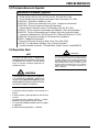
2.01 How to Use this Manual
To ensure safe operation, read the entire manual, including
the chapters on safety instructions and warnings.
Throughout this manual, the words WARNING, CAUTION,
and NOTE may appear. Pay particular attention to the
information provided under these headings. These special
annotations are easily recognized as follows:
WARNING
A WARNING GIVES INFORMATION REGARDING
POSSIBLE PERSONAL INJURY.
CAUTION
A CAUTION refers to possible equipment
damage.
NOTE
A NOTE offers helpful information concerning
certain operating procedures.
2.02 Receipt of Equipment
When you receive the equipment, check it against the
invoice to make sure it is complete and inspect the
equipment for possible damage due to shipping. If there is
any damage, notify the carrier immediately to file a claim.
Furnish complete information concerning damage claims
or shipping errors to the location in your area listed in the
inside back cover of this manual. Include a full description
of the parts in error.
If you want additional or replacement copies of this CD,
please contact Tweco
®
Robotics at the address and phone
number in your area listed on the inside back cover of this
manual. Include the Manual number (from page i) and
CD part number: 64-2601.
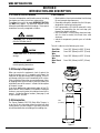
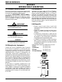
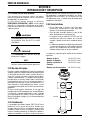
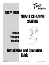
2.03 Introduction
The Tweco
®
Robotics QWT-120 Quick Wire Trimmer, is
an on-the-fly wire trimming station furnished with dual
cutting wheels as shown in Figure 1 that cleanly shear the
wire without deflection or bending of the welding wire.
SECTION 2:
INTRODUCTION AND DESCRIPTION
2.04 Features
Machined discs from heat-treated tool steel for long
life and economical performance.
Reversible cutting discs, doubles the disc’s life span,
designed for convenient replacement.
Unit is powered by a 120-volt AC motor with a relay
interface for controlling the start and stop cycle
through the robotic controller.
Unit is enclosed in a heavy-gauge aluminum tube,
with the head assembly machined from solid
aluminum.
Industrial components provide years of reliable
service.
The unit is able to cut the following wire sizes:
Steel Wire From .023” (0,6mm) to 5/64” (2,0mm)
Aluminum
Wire
From .030” (0,8mm) to 3/32” (3,2mm)
Flux Cored
Wire
From .030” (0,8mm) to 3/32” (3,2mm)
Metal Cored
Wire
From .030: (0,8mm) to 3/32” (3,2mm)
•
•
•
•
•
5.00”
(127mm)
17.00”
(432,5mm)
7.50”
(190,5mm)
5.00”
(126,4mm)
Figure 1

wire cutting station
3-5
SM-QWT-120
INSTALLATION AND OPERATION
SECTION 3:
INSTALLATION AND OPERATION
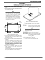
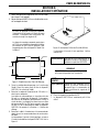
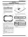
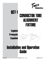
1. Remove the QWT-120 Wire Trimmer from the shipping
carton.
2. Mount the QWT-120 unit onto a solid work table within
the envelope of the robot.
NOTE
The cutting path should be within reach of the
end of the welding wire, at the desired angle
of cut. The unit may be mounted in a vertical
upright position, or at an angle of up to 30°.
The mounting plate has four .406” Ø (11,03mm)
holes that allow the use of 3/8” Ø (9,53mm)
hex head bolts to secure the unit to the
worktable. Refer to Figure 2.
Figure 2: Mounting Hole Location
7.12”
(180,8mm)
4.12”
(104,6mm)
8.00”
(203,2mm)
5.00”
(127mm)
Ø 0.406”
(11,03mm)
3. Lay out the hole pattern on the work table surface.
Drill the four holes and secure the QWT-120 unit to
the work table surface.
4. Plug the 120-volt AC power cord into the appropriate
receptacle.
The motor is controlled by a 24-volt DC relay circuit
built into the unit. The operational mode switch
activates the relay circuit. The unit comes with a 22/2
PVC control cable to receive the 24-volt DC signal
from the robot controller to the QWT-120 unit. Refer
to Section 4: Wiring Diagram.
5. Connect the 2 conductor control wires to the
robot controller per the robot manufacture’s
recommendations.
A three position toggle switch is located on the outer
housing of the QWT-120 unit. Refer to Figure 3.
Figure 3: Test/Off/Auto Toggle Switch
The 3-position toggle switch is used as follows:
TEST (UP) Allows the unit to function as long as
the switch is held in the UP position.
NOTE
Do not run the unit continuous, this may cause
overheating of the unit.
OFF (CENTER) Allows the unit to be turned off.
AUTO (DOWN) Allows the unit to be controlled ON or
OFF by the robot controller using the
24-volt DC signal.
6. Set the unit to the AUTO position.
7. The QWT-120 Unit is now ready to be used.

wire cutting station
4-6
SM-QWT-120
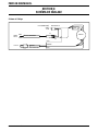
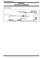
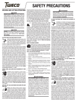
SECTION 4:
WIRING DIAGRAM
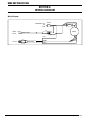
WIRING DIAGRAM
1
3
8
2
4
5
(MOMENTARY) TEST
OFF
AUTO
SWITCH
CAP
MOTOR
BLUE
BROWN
GREEN
POWER CORD
120 V AC
SIGNAL
24V DC
BLACK
RED
CONTROL WIRE
R1
R2
R3
R4
Wiring Diagram

wire cutting station
5-7
SM-QWT-120
REPLACEMENT PARTS
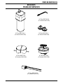
SECTION 5:
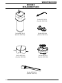
REPLACEMENT PARTS
Part No. QWT-120-9
(Stock No. 3500-1309)
Part No. QWT-120-6
(Stock No. 3500-1306)
Part No. QWT-120-19
(Stock No. 3500-1319)
Part No. QWT-120-2
(Stock No. 3500-1302)
Part No. QWT-120-4
(Stock No. 3500-1304)
Part No. QWT-120-20
(Stock No. 3500-1320)

wire cutting station
6-8
SM-QWT-120
FACTORY REPAIR CENTER
SECTION 6:
FACTORY REPAIR CENTER
Tweco
®
Robotics Factory Repair Center (FRC) offers a repair service for our customers on the various cable assemblies and
peripheral products. The majority of our consumers do not want to spend the time involved with repairs and generally do not
have the necessary equipment and tools to perform repairs.
Other key benefits in considering the “FRC” service repairs on your product:
All products will be rebuilt and tested following the established test procedures and specifications for the specific
product.
All repairs are done using original Tweco
®
Robotics parts to ensure maximum product performance.
Our FRC has highly-trained employees utilizing the appropriate tools and test equipment.
Factory Repair Center
Domestic Toll Free Phone Number: 1-800-426-1888
Fax Number: 1-620-229-9926
•
•
•

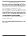
STATEMENT OF WARRANTY
LIMITED WARRANTY: THERMADYNE
®
warrants that its products will be free of defects in workmanship or material. Should
any failure to conform to this warranty appear within the time period applicable to the THERMADYNE products as stated below,
THERMADYNE shall, upon notification thereof and substantiation that the product has been stored, installed, operated, and
maintained in accordance with THERMADYNE’s specifications, instructions, recommendations and recognized standard industry
practice, and not subject to misuse, repair, neglect, alteration, or accident, correct such defects by suitable repair or replacement,
at THERMADYNE’s sole option, of any components or parts of the product determined by THERMADYNE to be defective.
THIS WARRANTY IS EXCLUSIVE AND IS IN LIEU OF ALL OTHER WARRANTIES, EXPRESS OR IMPLIED, INCLUDING ANY
WARRANTY OF MERCHANTABILITY OR FITNESS FOR A PARTICULAR PURPOSE.
LIMITATION OF LIABILITY:
THERMADYNE shall not under any circumstances be liable for special or consequential damages,
such as, but not limited to, damage or loss of purchased or replacement goods, or claims of customers of distributor (hereinafter
the “Purchaser”) for service interruption. The remedies of the Purchaser set forth herein are exclusive and the liability of
THERMADYNE with respect to any contract, or anything done in connection therewith such as the performance or breach
thereof, or from the manufacture, sale, delivery, resale, or use of any goods covered by or furnished by THERMADYNE whether
arising out of contract, negligence, strict tort, or under any warranty, or otherwise, shall not, except as expressly provided
herein, exceed the price of the goods upon which such liability is based.
THIS WARRANTY BECOMES INVALID IF REPLACEMENT PARTS OR ACCESSORIES ARE USED WHICH MAY IMPAIR THE
SAFETY OR PERFORMANCE OF ANY THERMADYNE PRODUCT.
THIS WARRANTY IS INVALID IF THE PRODUCT IS SOLD BY NON-AUTHORIZED PERSONS.
This warranty is effective for the time stated in the Warranty Schedule beginning on the date that the authorized distributor
delivers the products to the Purchaser.
Warranty repairs or replacement claims under this limited warranty must be submitted by an authorized THERMADYNE repair
facility within thirty (30) days of the repair. No transportation costs of any kind will be paid under this warranty. Transportation
charges to send products to an authorized warranty repair facility shall be the responsibility of the Purchaser. All returned goods
shall be at the Purchaser’s risk and expense. This warranty supersedes all previous THERMADYNE warranties.

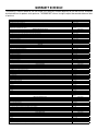
WARRANTY SCHEDULE
The warranty is effective below for the time stated in the Warranty Schedule beginning on the date that the authorized
distributor delivers the products to the purchaser. THERMADYNE
®
reserves the right to request documented evidence of date
of purchase.
Engine Driven Welders Parts / Labor
Scout
®
, Raider
®
, Explorer™
Original Main Power Stators and Inductors 3 years / 3 years
Original Main Power Rectifiers, Control P.C. Boards 3 years / 3 years
All Other Original Circuits and Components Including, but not Limited to, Relays, Switches, Contactors, Solenoids, Fans, Power Switch Semi-Conductors 1 year / 1 year
Engines and Associated Components are NOT Warranted by Thermal Arc
®
, Although Most are Warranted by the Engine Manufacturer. SEE THE ENGINE
MANUFACTURERS’ WARRANTY FOR DETAILS.
See the Engine Manufacturers’ Warranty
for Details
GMAW/FCAW (MIG) Welding Equipment Parts / Labor
Fabricator
®
131, 181, 190, 210, 251, 281; Fabstar
®
4030; PowerMaster
®
350, 350P, 500, 500P; Excel-Arc
®
6045; Wire Feeders: Ultrafeed
®
, Porta-feed
®
Original Main Power Transformer and Inductor 5 years / 3 years
Original Main Power Rectifiers, Control P.C. Boards, Power Switch Semi-Conductors 3 years / 3 years
All Other Original Circuits and Components Including, but not Limited to, Relays, Switches, Contactors, Solenoids, Fans, Electric Motors 1 year / 1 year
GTAW (TIG) & Multi-process Inverter Welding Equipment Parts / Labor
160TS, 300TS, 400TS, 185AC/DC, 200AC/DC, 300AC/DC, 400GTSW, 400MST, 300MST, 400MSTP
Original Main Power Magnetics 5 years / 3 years
Original Main Power Rectifiers, Control P.C. Boards, Power Switch Semi-Conductors 3 years / 3 years
All Other Original Circuits and Components Including, but not Limited to, Relays, Switches, Contactors, Solenoids, Fans, Electric Motors 1 year / 1 year
Plasma Welding Equipment Parts / Labor
Ultima
®
150
Original Main Power Magnetics 5 years / 3 years
Original Main Power Rectifiers, Control P.C. Boards, Power Switch Semi-Conductors 3 years / 3 years
Welding Console, Weld Controller, Weld Timer 3 years / 3 years
All Other Original Circuits and Components Including, but not Limited to, Relays, Switches, Contactors, Solenoids, Fans, Electric Motors, Coolant Recirculators 1 year / 1 year
SMAW (Stick) Welding Equipment Parts / Labor
Dragster™ 85
Original Main Power Magnetics 1 year / 1 year
Original Main Power Rectifiers, Control P.C. Boards 1 year / 1 year
All Other Original Circuits and Components Including, but not Limited to, Relays, Switches, Contactors, Solenoids, Fans, Power Switch Semi-Conductors 1 year / 1 year
160S, 300S, 400S
Original Main Power Magnetics 5 years / 3 years
Original Main Power Rectifiers, Control P.C. Boards 3 years / 3 years
All Other Original Circuits and Components Including, but not Limited to, Relays, Switches, Contactors, Solenoids, Fans, Power Switch Semi-Conductors 1 year / 1 year
General Arc Equipment Parts / Labor
Water Recirculators 1 year / 1 year
Plasma Welding Torches 180 days / 180 days
Gas Regulators (Supplied with Power Sources) 180 days / NA
MIG and TIG Torches (Supplied with Power Sources) 90 days / NA
Replacement Repair Parts 90 days / NA
MIG, TIG and Plasma Welding Torch Consumable Items NA / NA
Gas Welding and Cutting Equipment Parts / Labor
Victor
®
Professional 5 years / NA
Oxygen Conservers 2 years / NA
Aluminum Cylinders Lifetime / NA
Cutting Machine Motors 1 year / NA
HP&I Brass Regulators/Manifolds 2 years / NA
HP&I Stainless Regulators/Manifolds 1 year / NA
HP&I Corrosive Gas Regulators/Manifolds 90 days / NA
TurboTorch
®
3 years / NA
CutSkill
®
2 years / NA
Steel Cylinders 1 year / NA
Victor Medical 6 years / NA
Victor VSP 2 years / NA
Firepower
®
MIG Welders 5-2-1 years / NA
Transformers 5 years / NA
Parts Used in Rental Applications
1 year from date sold by seller to authorized
distributor
MIG Torches and Arc Accessories Parts / Labor
Arcair
®
N6000 90 days / NA
Eliminator
®
Spool and Pull Guns 90 days / NA
Robotic Deflection Mounts 90 days / NA
QRM-100 Anti-Spatter Applicator 90 days / NA
TC and TCV Water Coolers 1 year / NA
TSC-96 Smoke Collector 1 year / NA
ESG-1, EPG-CR1, EPG-CR2 Control Boxes for Eliminator Spool & Pull Guns 1 year / NA
QRC-2000 Nozzle Cleaning Stations 1 year / 1 year
QRC-3000 UltraSonic Cleaning Stations 2 years / 2 years
All other products 30 days from date purchaser purchases from seller. 30 days / NA
Plasma Cutting Systems Parts / Labor
Automated Plasma 2 years / 1 year
CutMaster™ 3 years / 3 years
PakMaster
®
XL PLUS 3 years / 1 year
Drag-Gun
®
1 year / 1 year
Drag-Gun Plus 2 years / 1 year
Torches 1 year / 1 year
Consoles, Control Equipment, Heat Exchangers and Accessory Equipment 1 year / 1 year


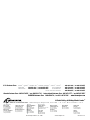
© Thermadyne Industries, Inc., 2008 www.thermadyne.com Printed in U.S.A.
W O R L D H E A D Q U A R T E R S : 1 6 0 5 2 S w i n g l e y R i d g e R o a d , S u i t e 3 0 0 • S t . Lo u i s , M i s s o u r i 6 3 0 1 7 U. S . A .
A Global Cutting & Welding Market Leader
™
Denton, TX USA
U.S. Customer Care
Ph: (1) 800-426-1888
Fax: (1) 800-535-0557
Miami, FL USA
Sales Office, Latin America
Ph: (1) 954-727-8371
Fax: (1) 954-727-8376
Oakville, Ontario, Canada
Canada Customer Care
Ph: (1) 905-827-4515
Fax: (1) 800-588-1714
International Customer Care
Ph: (1) 905-827-9777
Fax: (1) 905-827-9797
Chorley, United Kingdom
Customer Care
Ph: (44) 1257-261755
Fax: (44) 1257-224800
Milan, Italy
Customer Care
Ph: (39) 0236546801
Fax: (39) 0236546840
Cikarang, Indonesia
Customer Care
Ph: 62 21+ 8983-0011 / 0012
Fax: 62 21+ 893-6067
Osaka, Japan
Sales Office
Ph: 816-4809-8411
Fax: 816-4809-8412
Melbourne, Australia
Australia Customer Care
Ph: 1300-654-674
Fax: 613+ 9474-7391
International
Ph: 613+ 9474-7508
Fax: 613+ 9474-7488
Rawang, Malaysia
Customer Care
Ph: 603+ 6092-2988
Fax: 603+ 6092-1085
Shanghai, China
Sales Office
Ph: 86-21-64072626
Fax: 86-21-64483032
Singapore
Sales Office
Ph: 65+ 6832-8066
Fax: 65+ 6763-5812
THE AMERICAS EUROPE ASIA/PACIFIC
U.S. Customer Care: ARCAIR
®
/ STOODY
®
/ THERMAL ARC
®
/ THERMAL DYNAMICS
®
/ TWECO
®
/ VICTOR
®
................... 800-426-1888 / FAX 800-535-0557
FIREPOWER
®
................. 800-858-4232 / FAX 800-535-0557 TDC AUTOMATION................... 866-279-2628 / FAX 800-535-0557
TURBOTORCH
®
............. 800-238-0282 / FAX 800-535-0557 VICTOR MEDICAL .................... 800-382-8187 / FAX 800-535-0557
VICTOR SPECIALTY PRODUCTS ................... 800-569-0547 / FAX 800-535-0557
Canada Customer Care: 905-827-4515 / FAX 800-588-1714
•
International Customer Care: 905-827-9777 / FAX 905-827-9797
CIGWELD Customer Care: 1300-654-674 / FAX 613+ 9474-7391
•
www.thermadyne.com

50
60
Hz
1
PHASE
GTAW
SMAW
INVERTER
CC
DC
115
V
230
V
POSTE DE COUPE
DE FIL
Guide D’installation
et D’utilisation
English
Français
Español
QWT-120
Révision: A Date d’émission: 12 novembre 2008 No de Forma: SM-QWT-120

50
60
Hz
1
PHASE
GTAW
SMAW
INVERTER
CC
DC
115
V
230
V
VOTRE ACTIVITÉ NOUS INTÉRESSE!
Félicitations pour votre nouveau produit Tweco
®
. Nous sommes fiers de
vous avoir comme client et nous tâcherons de vous fournir les meilleurs
services et fiabilité dans l’industrie. Ce produit est soutenu par une vaste
garantie et un réseau mondial de service. Pour localiser votre distributeur
ou agence de service le plus proche, veuillez communiquer avec un
représentant à l’adresse ou au numéro de téléphone correspondant à
votre région, indiqué au verso de la couverture du manuel, ou visitez
notre site web www.tweco.com.
Ce Manuel d’utilisation a été conçu pour vous permettre d’utiliser et de
faire fonctionner correctement votre produit Tweco
®
. Votre satisfaction
et le fonctionnement en toute sécurité de votre produit sont nos
principaux soucis. Par conséquent, veuillez prendre le temps de lire
tout le manuel, spécialement en ce qui concerne les Précautions de
Sécurité. Ceci vous aidera à éviter d’éventuels accidents qui pourraient
survenir en travaillant avec ce produit.
VOUS ÊTES EN BONNE COMPAGNIE!
La Marque de Choix pour les Entrepreneurs et les Fabricants dans le Monde.
Tweco
®
Robotics est une marque globale de produits de soudage à l’arc
pour Thermadyne Industries Inc. Nous fabriquons et fournissons aux
plus grands secteurs de l’industrie de soudage dans le monde dont:
Fabrication, Construction, Exploitation Minière, Automobile, Aérospatial,
Ingénierie, Rural et Loisirs/Bricolage.
Nous nous distinguons de notre concurrence grâce à nos produits
en tête du marché, fiables, ayant résisté à l’épreuve du temps. Nous
sommes fiers de notre innovation technique, nos prix compétitifs, notre
excellente livraison, notre service clientèle et notre support technique
de qualité supérieure, ainsi que de l’excellence dans les ventes et
l’expertise en marketing.
Surtout, nous nous engageons à développer des produits utilisant des
technologies de pointe pour obtenir un environnement de travail plus
sécurisé dans l’industrie de la soudure.

AVERTISSEMENT
LISEZ ET COMPRENEZ TOUT LE MANUEL ET LES PRATIQUES DE SÉCURITÉ DE L’UTILISATEUR AVANT L’INSTALLATION,
LE FONCTIONNEMENT OU L’ENTRETIEN DE L’ÉQUIPEMENT. MÊME SI LES INFORMATIONS CONTENUES DANS CE MANUEL
REPRÉSENTENT LE MEILLEUR JUGEMENT DU FABRICANT, CELUI-CI N’ASSUME AUCUNE RESPONSABILITÉ POUR SON
USAGE.
Poste de Coupe de Fil
Guide D’installation et D’utilisation
Numéro du Manuel d’Instructions pour SM-QWT-120
Publié par:
Tweco
®
Products Inc.
2800 Airport Road
Denton, TX 76208
(940) 566-2000
www.tweco.com
Copyright © 2008 par
Thermadyne Industries Inc.
® Tous droits réservés.
La reproduction, de tout ou partie de ce manuel, sans l’autorisation écrite de l’éditeur, est interdite.
L’éditeur n’assume pas et dément toute responsabilité pour perte ou dommage causés à une partie par erreur ou
omission dans ce manuel, si une telle erreur résulte d’une négligence, d’un accident, ou de toute autre cause.
Date de Parution: 12 novembre 2008
Complétez les informations suivantes à des fins de garantie:
Lieu D’achat: ________________________
Date D’achat: ________________________
Numéro de: ________________________
i

Poste de CouPe de Fil
ii
SM-QWT-120
Table des Matiéres
SECTION 1: INSTRUCTIONS DE SÉCURITÉ ET MISES EN GARDE .............................F1-1
1.01 Accidents de Soudage ............................................................................. F1-1
1.02 Principales Normes de Sécurité ..............................................................F1-3
1.03 Sécurité et Santé .....................................................................................F1-3
SECTION 2: INTRODUCTION ET DESCRIPTION ..................................................F2-4
2.01 Comment Utiliser ce Manuel ...................................................................F2-4
2.02 Réception de L’équipement .....................................................................F2-4
2.03 Introduction ............................................................................................F2-4
2.04 Dispositifs ...............................................................................................F2-4
SECTION 3: INSTALLATION ET OPÉRATION ..........................................................
5
SECTION 4: SCHÉMA DE CÂBLAGE ................................................................
F4-6
SECTION 5: PIÈCES DE RECHANGE ................................................................
F5-7
GARANTIE .............................................................................................F6-8
TABLEAU DES GARANTIES ..........................................................................
F6-9
La page est en cours de chargement...
La page est en cours de chargement...
La page est en cours de chargement...
La page est en cours de chargement...
La page est en cours de chargement...
La page est en cours de chargement...
La page est en cours de chargement...
La page est en cours de chargement...
La page est en cours de chargement...
La page est en cours de chargement...
La page est en cours de chargement...
La page est en cours de chargement...
La page est en cours de chargement...
La page est en cours de chargement...
La page est en cours de chargement...
La page est en cours de chargement...
La page est en cours de chargement...
La page est en cours de chargement...
La page est en cours de chargement...
La page est en cours de chargement...
La page est en cours de chargement...
La page est en cours de chargement...
La page est en cours de chargement...
La page est en cours de chargement...
-
 1
1
-
 2
2
-
 3
3
-
 4
4
-
 5
5
-
 6
6
-
 7
7
-
 8
8
-
 9
9
-
 10
10
-
 11
11
-
 12
12
-
 13
13
-
 14
14
-
 15
15
-
 16
16
-
 17
17
-
 18
18
-
 19
19
-
 20
20
-
 21
21
-
 22
22
-
 23
23
-
 24
24
-
 25
25
-
 26
26
-
 27
27
-
 28
28
-
 29
29
-
 30
30
-
 31
31
-
 32
32
-
 33
33
-
 34
34
-
 35
35
-
 36
36
-
 37
37
-
 38
38
-
 39
39
-
 40
40
-
 41
41
-
 42
42
-
 43
43
-
 44
44


Tweco Robotics QWT-120 Wire Cutting Station Guide d'installation
- Taper
- Guide d'installation
dans d''autres langues
Documents connexes
-
 Tweco Robotics QWT-3 Quick Wire Trim Unit Guide d'installation
-
Tweco Robotics Light Weight Quick Robotics Torch Guide d'installation
-
 Tweco Robotics Quick Fixed Automation Series Torches Guide d'installation
-
 Tweco Robotics Quick Robotic Torch Guide d'installation
-
 Tweco Robotics QWT-120 Wire Cutting Station Guide d'installation
-
 Tweco Robotics QRC-3000LS QRC-3000IO Ultrasonic Nozzle Cleaning Station Manuel utilisateur
-
 Tweco Robotics QRM-100 Anti-Spatter Mist Applicator Guide d'installation
-
 Tweco Robotics QRP-IN TCP Check Tool Guide d'installation
-
 Tweco Robotics QRC™-2000 Nozzle Cleaning Station Guide d'installation
-
 Tweco Robotics QCT-1 Conductor Tube Alignment Fixture Guide d'installation


Autres documents
-
 Tweco Air-Cooled 350 AMP 450 AMP Water-Cooled 400 AMP 500 AMP PulseMaster™ Mig Gun Manuel utilisateur
-
 Tweco Welding and Cutting Operations Manuel utilisateur
-
 Thermal Dynamics 42 CUTMASTER® Plasma Cutting System Manuel utilisateur
-
 Tweco Smoke Collector Manuel utilisateur
-
Thermal Dynamics Plasma Cutting System Model Drag-Gun Plus Manuel utilisateur
-
 Thermal Arc 350 350P 500 500P Powermaster CC/CV Power Source Manuel utilisateur
-
ESAB Robotics RDM-2000 Robotic Deflection Mount Guide d'installation
-
-
-


