Mitsubishi Electric PXZ-4F75VG Split-Type Air-Conditioner Manuel utilisateur
- Catégorie
- Climatiseurs split-system
- Taper
- Manuel utilisateur

Split-type Air-Conditioner
PXZ-4F75VG
Türkçe
Svenska
Dansk
Português
Ελληνικά
Italiano
Español
Nederlands
Français
Deutsch
English
Installation Manual For INSTALLER
• This manual only describes the installation of outdoor unit.
When installing the indoor unit, refer to the installation manual of indoor unit.
Installationsanleitung Für INSTALLATEUR
• Diese Installationsanleitung gilt nur für die Installation des Außengerätes.
Zur Installation des Innengeräts siehe die Installationsanleitung für Innengeräte.
Notice d’installation
Destinée à l
’
INSTALLATEUR
• Cette notice ne décrit que l’installation de l’appareil extérieur.
Lors de l’installation de l’appareil intérieur, consultez la notice d’installation de
cet appareil.
Installatiehandleiding Voor de INSTALLATEUR
• Deze handleiding beschrijft alleen de installatie van de buitenunit.
Raadpleeg de installatiehandleiding van de binnenunit wanneer u deze
installeert.
Manual de instalación Para el INSTALADOR
• En este manual sólo se describe la instalación de la unidad exterior.
Para instalar la unidad interior, consulte el manual de instalación de dicha
unidad.
Manuale per l’installazione
Per il TECNICO INSTALLATORE
• Questo manuale descrive solo l’installazione dell’unità esterna.
Per l’installazione dell’unità interna, fare riferimento al relativo manuale di
installazione.
Εγχειρίδιο εγκατάστασης Για τον ΤΕΧΝΙΚΟ
•
Στο παρόν εγχειρίδιο περιγράφεται μόνο η εγκατάσταση της μονάδας εξωτερικού χώρου.
Για την εγκατάσταση της μονάδας εσωτερικού χώρου, ανατρέξτε στο εγχειρίδιο
εγκατάστασης της μονάδας εσωτερικού χώρου.
Manual de Instalação Para o INSTALADOR
• Este manual descreve apenas a instalação da unidade exterior.
Quando proceder à instalação da unidade interior, consulte o manual de instalação
da unidade interior.
Installationshåndbog Til INSTALLATØREN
• Denne håndbog beskriver kun, hvordan udendørsenheden installeres.
Vedrørende installation af indendørsenheden henvises til installationshåndbogen
for indendørsenheden.
Installationsanvisning För INSTALLATÖREN
• Denna installationsanvisning beskriver endast installation av utomhusenheten.
Se den separata installationsanvisningen för inomhusenheten.
Kurulum Kılavuzu TESİSATÇI İÇİN
• Bu kılavuzda yalnızca dış ünitenin kurulumu açıklanmaktadır.
İç ünite kurulum işlemini yaparken iç ünite kurulum kılavuzuna bakın.
English is original.
Übersetzung des
Originals
Traduction du texte
d’origine
Vertaling van het
origineel
Traducción del
original
Traduzione
dell’originale
Μετάφραση του
αρχικού
Tradução do
original
Oversættelse af
den originale tekst
Översättning från
originalet
Orijinalin çevirisi
Ръководство за монтаж За ИНСТАЛАТОРА
•
Това ръководство описва само монтажа на външното тяло.
При монтиране на вътрешното тяло вижте ръководството за монтаж на
вътрешното тяло.
Оригиналът е текстът
на английски език.
Български
Norsk
Installasjonshåndbok For INSTALLATØR
• Denne håndboken beskriver installasjonen av den utvendige enheten.
Når den innvendige enheten skal installeres, se installasjonshåndboken til den
innvendige enheten.
Originalspråket er
engelsk.
Polski
Instrukcja montażu DLA INSTALATORA
• Niniejsza instrukcja zawiera tylko opis instalacji jednostki zewnętrznej.
W przypadku instalowania jednostki wewnętrznej należy odnieść się do instrukcji
montażu jednostki wewnętrznej.
Językiem oryginału
jest język angielski.
VH79A038H01_cover.indd 1 2022/09/12 9:56:53

EN Go to the above website to download manuals, select model name, then choose language.
DE Besuchen Sie die oben stehende Website, um Anleitungen herunterzuladen, wählen Sie den Modellnamen und dann die Sprache aus.
FR Rendez-vous sur le site Web ci-dessus pour télécharger les manuels, sélectionnez le nom de modèle puis choisissez la langue.
NL Ga naar de bovenstaande website om handleidingen te downloaden, de modelnaam te selecteren en vervolgens de taal te kiezen.
ES Visite el sitio web anterior para descargar manuales, seleccione el nombre del modelo y luego elija el idioma.
IT Andare sul sito web indicato sopra per scaricare i manuali, selezionare il nome del modello e scegliere la lingua.
EL Μεταβείτε στον παραπάνω ιστότοπο για να κατεβάσετε εγχειρίδια. Επιλέξτε το όνομα του μοντέλου και, στη συνέχεια, τη γλώσσα.
PT Aceda ao site Web acima indicado para descarregar manuais, seleccione o nome do modelo e, em seguida, escolha o idioma.
DA Gå til ovenstående websted for at downloade manualer og vælge modelnavn, og vælg derefter sprog.
SV Gå till ovanstående webbplats för att ladda ner anvisningar, välj modellnamn och välj sedan språk.
TR Kılavuzları indirmek için yukarıdaki web sitesine gidin, model adını ve ardından dili seçin.
RU Чтобы загрузить руководства, перейдите на указанный выше веб-сайт; выберите название модели, а затем язык.
UK Щоб завантажити керівництва, перейдіть на зазначений вище веб-сайт; виберіть назву моделі, а потім мову.
BG Посетете горепосочения уебсайт, за да изтеглите ръководства, като изберете име на модел и след това – език.
PL Odwiedź powyższą stronę internetową, aby pobrać instrukcje, wybierz nazwę modelu, a następnie język.
CS Příručky naleznete ke stažení na internetové stránce zmíněné výše poté, co zvolíte model a jazyk.
SK Na webovej stránke vyššie si môžete stiahnuť návody. Vyberte názov modelu a zvoľte požadovaný jazyk.
HU A kézikönyvek letöltéséhez látogasson el a fenti weboldalra, válassza ki a modell nevét, majd válasszon nyelvet.
SL Obiščite zgornjo spletno stran za prenos priročnikov; izberite ime modela, nato izberite jezik.
RO Accesaţi site-ul web de mai sus pentru a descărca manualele, selectaţi denumirea modelului, apoi alegeţi limba.
ET Kasutusjuhendite allalaadimiseks minge ülaltoodud veebilehele, valige mudeli nimi ja seejärel keel.
LV Dodieties uz iepriekš norādīto tīmekļa vietni, lai lejupielādētu rokasgrāmatas; tad izvēlieties modeļa nosaukumu un valodu.
LT Norėdami atsisiųsti vadovus, apsilankykite pirmiau nurodytoje žiniatinklio svetainėje, pasirinkite modelio pavadinimą, tada – kalbą.
HR Kako biste preuzeli priručnike, idite na gore navedeno web-mjesto, odaberite naziv modela, a potom odaberite jezik.
SR Idite na gore navedenu veb stranicu da biste preuzeli uputstva, izaberite ime modela, a zatim izaberite jezik.
NO Gå til nettstedet over for å laste ned håndbøker og velg modellnavn, og velg deretter språk.
FI Mene yllä mainitulle verkkosivulle ladataksesi oppaat, valitse mallin nimi ja valitse sitten kieli.
Manual Download
http://www.mitsubishielectric.com/ldg/ibim/
VH79A038H01_cover.indd 2 2022/09/12 9:56:54

1
en
1-1. THE FOLLOWING SHOULD ALWAYS BE OBSERVED FOR SAFETY
• Be sure to read “THE FOLLOWING SHOULD ALWAYS BE OBSERVED FOR SAFETY” before installing the air conditioner.
• Besuretoobservethewarningsandcautionsspeciedhereastheyincludeimportantitemsrelatedtosafety.
• Afterreadingthismanual,besuretokeepittogetherwiththeOPERATINGINSTRUCTIONSforfuturereference.
■ Do not install the unit by yourself (user).
Incompleteinstallationcouldcausereorelectricshock,injuryduetotheunit
falling,orleakageofwater.Consultthedealerfromwhomyoupurchasedthe
unitoraqualiedinstaller.
■ Perform the installation securely referring to the installation manual.
Incomplete installation could cause re, electric shock, injury due to the unit
falling,orleakageofwater.
■ When installing the unit, use appropriate protective equipment and tools
for safety.
Failuretodosocouldcauseinjury.
■ Install the unit securely in a place which can bear the weight of the unit.
Iftheinstallationlocationcannotbeartheweightoftheunit,theunitcouldfall
causinginjury.
■ Electrical work should be performed by a qualied, experienced electri-
cian, according to the installation manual. Be sure to use an exclusive
circuit. Do not connect other electrical appliances to the circuit.
Ifthecapacityofthepowercircuitisinsufcientorthereisincompleteelectrical
work,itcouldresultinareoranelectricshock.
■ Do not damage the wires by applying excessive pressure with parts or
screws.
Damagedwirescouldcausereorelectricshock.
■ Be sure to cut off the main power in case of setting up the indoor P.C.
board or wiring works.
Failuretodosocouldcauseelectricshock.
■ Use the specied wires to connect the indoor and outdoor units securely
and attach the wires rmly to the terminal block connecting sections so
the stress of the wires is not applied to the sections. Do not extend the
wires, or use intermediate connection.
Incompleteconnectingandsecuringcouldcausere.
■ Do not install the unit in a place where inammable gas may leak.
Ifgasleaksandaccumulatesintheareaaroundtheunit,itcouldcauseanexplosion.
■ Do not use intermediate connection of the power cord or the extension
cord and do not connect many devices to one AC outlet.
Itcouldcause a reoranelectricshockduetodefectivecontact,defective
insulation,exceedingthepermissiblecurrent,etc.
■ Be sure to use the parts provided or specied parts for the installation
work.
Theuseofdefectivepartscouldcauseaninjuryorleakageofwaterduetoare,
anelectricshock,theunitfalling,etc.
■ When plugging the power supply plug into the outlet, make sure that
there is no dust, clogging, or loose parts in both the outlet and the plug.
Make sure that the power supply plug is pushed completely into the
outlet.
Ifthereisdust,clogging,orloosepartsonthepowersupplyplugortheoutlet,it
couldcauseelectricshockorre.Ifloosepartsarefoundonthepowersupply
plug,replaceit.
■ Attach the electrical cover to the indoor unit and the service panel to the
outdoor unit securely.
If the electrical cover of the indoor unit and/or the service panel of the outdoor
unitarenotattachedsecurely,itcouldresultinareoranelectricshockdueto
dust,water,etc.
■ When installing, relocating, or servicing the unit, make sure that no
substance other than the specied refrigerant (R32) enters the refrigerant
circuit.
Anypresenceofforeignsubstancesuchasaircancauseabnormalpressure
riseandmayresultinexplosionorinjury.Theuseofanyrefrigerantotherthan
thatspeciedforthesystemwillcausemechanicalfailure,systemmalfunction,
orunitbreakdown.Intheworstcase,thiscouldleadtoaseriousimpedimentto
securingproductsafety.
■ Do not discharge the refrigerant into the atmosphere. If refrigerant leaks
during installation, ventilate the room. Check that the refrigerant does
not leak after installation has been completed.
Ifrefrigerantleaksandcomesincontactwithreorheatingpartofsuchafan
heater,keroseneheater, orcookingstove,itwillcreateharmfulgas.Provide
ventilation in accordance with EN378-1.
■ Check that the refrigerant gas does not leak after installation has been
completed.
Ifrefrigerantgasleaksindoors,andcomesintocontactwiththeameofafan
heater,spaceheater,stove,etc.,harmfulsubstanceswillbegenerated.
■ Use appropriate tools and piping materials for installation.
ThepressureofR32is1.6timesmorethanR22.Notusingappropriatetoolsor
materialsandincompleteinstallationcouldcausethepipestoburstorinjury.
■ When the refrigeration circuit has a leak, do not execute pump down with
the compressor.
■ When pumping down the refrigerant, stop the compressor before discon-
necting the refrigerant pipes.
Iftherefrigerantpipearedisconnectedwhilethecompressorisrunningandthe
stopvalveisopen,aircouldbedrawninandthepressureintherefrigeration
cyclecouldbecomeabnormallyhigh.
Thecompressormayburstandcauseinjuryifanyforeignsubstance,suchas
air,entersthepipes.
■ When installing the unit, securely connect the refrigerant pipes before
starting the compressor.
Ifthecompressorisstartedbeforetherefrigerantpipesareconnectedandwhen
thestopvalveisopen,aircouldbedrawninandthepressureintherefrigeration
cyclecouldbecomeabnormallyhigh.Thiscouldcausethepipestoburstorinjury.
■ Fasten a are nut with a torque wrench as specied in this manual.
Iffastenedtootight,aarenutmaybreakafteralongperiodandcauserefrigerant
leakage.
■ The unit shall be installed in accordance with national wiring regulations.
■ Earth the unit correctly.
Donotconnecttheearthtoagaspipe,waterpipe,lightningrodortelephone
earth.Defectiveearthingcouldcauseelectricshock.
■ Be sure to install an earth leakage breaker.
Failuretoinstallanearthleakagebreakermayresultinelectricshockorre.
■ When using a gas burner or other ame-producing equipment, com-
pletely remove all of the refrigerant from the air conditioner and ensure
that the area is well-ventilated.
Iftherefrigerantleaksandcomesincontactinreorheatingpart,itwillcreate
harmfulgasandthereisriskofre.
■ Do not use means to accelerate the defrosting process or to clean, other
than those recommended by the manufacturer.
■ The appliance shall be stored in a room without continuously operating
ignition sources (for example: open ames, an operating gas appliance
or an operating electric heater).
■ Do not pierce or burn.
■ Be aware that refrigerants may not contain an odour.
■ Pipe-work shall be protected from physical damage.
■ The installation of pipe-work shall be kept to a minimum.
■ Compliance with national gas regulations shall be observed.
■ Keep any required ventilation openings clear of obstruction.
■ Do not use low temperature solder alloy in case of brazing the refrigerant
pipes.
■ Servicing shall be performed only as recommended by the manufacturer.
■ Do not alter the unit. It may cause re, electric shock, injury or water
leakage.
■ When opening or closing the valve below freezing temperatures, refriger-
ant may spurt out from the gap between the valve stem and the valve
body, resulting in injuries.
■ The appliance shall be stored in a well-ventilated area where the room
size corresponds to the room area as specied for operation.
■ If the supply cord is damaged, it must be replaced by the manufacturer,
its service agent or similarly qualied persons in order to avoid a hazard.
WARNING (Couldleadtodeath,seriousinjury,etc.)
Required Tools for Installation
Phillipsscrewdriver
Level
Scale
Utilityknifeorscissors
Torque wrench
Wrench(orspanner)
4mmhexagonalwrench
FlaretoolforR32,R410A
GaugemanifoldforR32,R410A
VacuumpumpforR32,R410A
ChargehoseforR32,R410A
Pipecutterwithreamer
ENGLISH
1. BEFORE INSTALLATION
MEANINGS OF SYMBOLS DISPLAYED ON INDOOR UNIT AND/OR OUTDOOR UNIT
WARNING
(Riskofre)
Thisunitusesaammablerefrigerant.
Ifrefrigerantleaksandcomesincontactwithreorheatingpart,itwillcreateharmfulgasandthereisriskofre.
ReadtheOPERATINGINSTRUCTIONScarefullybeforeoperation.
ServicepersonnelarerequiredtocarefullyreadtheOPERATINGINSTRUCTIONSandINSTALLATIONMANUALbeforeoperation.
FurtherinformationisavailableintheOPERATINGINSTRUCTIONS,INSTALLATIONMANUAL,andthelike.
CONTENTS
1. BEFORE INSTALLATION .........................................................................1
2. OUTDOOR UNIT INSTALLATION ............................................................8
3.FLARINGWORKANDPIPECONNECTION ............................................9
4.PURGINGPROCEDURES,LEAKTEST,ANDTESTRUN ....................11
5.PUMPINGDOWN ...................................................................................15
6.
PRECAUTIONSWHENCONNECTINGTHECYLINDERUNIT/HYDROBOX/DHWTANK
...16
VH79A038H01_01En.indd 1 2022/08/22 13:18:00

2
en
CAUTION (Couldleadtoseriousinjuryinparticularenvironmentswhenoperatedincorrectly.)
■ Install an earth leakage breaker depending on the installation place.
Ifanearthleakagebreakerisnotinstalled,itcouldcauseelectricshock.
■ Perform the drainage/piping work securely according to the installation
manual.
Ifthereis defectin thedrainage/piping work,watercould dropfrom theunit,
soakinganddamaginghouseholdgoods.
■ Do not touch the air inlet or the aluminum ns of the outdoor unit.
Thiscouldcauseinjury.
■ Do not install the outdoor unit where small animals may live.
Ifsmallanimalsenterandtouchtheelectricpartsinsidetheunit,itcouldcausea
malfunction,smokeemission,orre.Also,adviseusertokeeptheareaaround
the unit clean.
■ Do not operate the air conditioner during interior construction and nish-
ing work, or while waxing the oor.
Beforeoperatingtheairconditioner,ventilatetheroomwellaftersuchworkis
performed.Otherwise,itmaycausevolatileelementstoadhereinsidetheair
conditioner,resultinginwaterleakageorscatteringofdew.
■ When there are the ports which are not used, make sure their nuts are
tightened securely.
■ When charging the refrigerant system with additional refrigerant, be sure
to use liquid refrigerant. Charge the liquid refrigerant slowly, otherwise
the compressor will be locked.
Tomaintainthehighpressureofthegascylinder,warmthegascylinderwith
warmwater(under40°C)duringcoldseason.Butneverusenakedreorsteam.
1-2. SPECIFICATIONS
1-3. SELECTING OPTIONAL DIFFERENT-DIAMETER JOINTS
Ifthediameterofconnectionpipedoesnotmatchtheportsizeofoutdoorunit,useoptionaldifferent-diameterjointsaccordingtothefollowingtable.
(Unit:mm(inch))
Portsizeofoutdoorunit Optionaldifferent-diameterjoints
(portsizeofoutdoorunit→diameterofconnectionpipe)
PXZ-4F75VG Liquid / Gas 6.35(1/4)→9.52(3/8):PAC-493PI
9.52(3/8)→12.7(1/2):MAC-A454JP-E
9.52(3/8)→15.88(5/8):PAC-SG76RJ-E
12.7(1/2)→9.52(3/8):MAC-A455JP-E
12.7(1/2)→15.88(5/8):MAC-A456JP-E
Refertotheinstallationmanualofindoorunitforthediameterofconnection
pipe of indoor unit.
A UNIT 6.35(1/4)/12.7(1/2)
B - D UNIT 6.35(1/4)/9.52(3/8)
*1 Connecttothepowerswitchwhichhasagapof3mmormorewhenopentointerruptthe
sourcepowerphase.(Whenthepowerswitchisshutoff,itmustinterruptallphases.)
*2 Usewiresinconformitywithdesign60245IEC57.Usetheindoor/outdoorconnectingwire
inconformitywiththewirespecicationsspeciedintheinstallationmanualoftheindoor
unit.
*3 Neverusepipeswiththicknesslessthanspecied.Thepressureresistancewillbeinsuf-
cient.
*4 Useacopperpipeoracopper-alloyseamlesspipe.
*5 Be careful not to crush or bend the pipe during pipe bending.
*6 Refrigerantpipebendingradiusmustbe100mmormore.
*7 Insulationmaterial:Heatresistingfoamplastic0.045specicgravity
*8 Besuretousetheinsulationofspeciedthickness.Excessivethicknessmaycauseincor-
rectinstallationoftheindoorunitandinsufcientthicknessmaycausedewdrippage.
*9 Iftheoutdoorunitisinstalledhigherthantheindoorunit,max.heightdifferenceisreduced
to10m.
*10Thepipingspecicationtabledoesnotprovideaminimumlinesetlength.
However,indoorunitswithconnectedpipinglengthlessthan3mcouldproduceintermit-
tentnoiseduringnormalsystemoperationinveryquietenvironments.
Pleasebeawareofthisimportantinformationwheninstallingandlocatingtheindoorunit
within the conditioned space.
*11 WhenAirtoairindoorunits(ATAINDOORUNITS,Mseries/Sseries/Pseriesindoor
units)operation.
1-4. SELECTING THE INSTALLATION LOCATION
• Whereitisnotexposedtostrongwind.
• Whereairowisgoodanddustless.
• Whererainordirectsunshinecanbeavoidedasmuchaspossible.
• Whereneighboursarenotannoyedbyoperationsoundorhotair.
• Where rigid wall or support is available to prevent the increase of opera-
tion sound or vibration.
• Wherethereisnoriskofcombustiblegasleakage.
• Wheninstallingtheunit,besuretosecuretheunitlegs.
• Whereitisatleast3mawayfromtheantennaofTVsetorradio.Opera-
tionoftheairconditionermayinterferewithradioorTVreceptioninareas
wherereceptionisweak.Anampliermayberequiredfortheaffected
device.
• Installtheunithorizontally.
• Pleaseinstallitinanareanotaffectedbysnowfallorblowingsnow.In
areaswithheavysnow,pleaseinstallacanopy,apedestaland/orsome
bafeboards.
Note:
Itisadvisabletomakea pipingloop nearoutdoorunitsoastoreduce
vibrationtransmittedfromthere.
Model
Powersupply*1 Wirespecications*2 Pipelengthandheightdifference
*3,*4,*5,*6,*7,*8,*10
Outdoor Noise level
*11
Rated
Voltage
Fre-
quency
Breaker
capacity
Power
supply
Indoor/outdoor
connecting
wire
Max.pipelength
per indoor unit /
formulti-system
Max.height
difference *9
Max.no.ofbends
per indoor unit / for
multisystem
Cooling Heating
PXZ-4F75VG 230V 50Hz 25 A 3-core
2.5mm2
4-core
1.0/1.5mm230m/60m 20m 25/60 48dB(A) 54dB(A)
Model Maximumamountof
refrigerant charge
Factory-charged
refrigerantamount
PXZ-4F75VG 2.4kg 2.4kg
Note:
Whenoperatingtheairconditionerinlowoutsidetemperature,besure
to follow the instructions described below.
• Never install the outdoor unit in a place where its air inlet/outlet side
maybeexposeddirectlytowind.
• Topreventexposuretowind,installtheoutdoorunitwithitsairinlet
side facing the wall.
•
Topreventexposuretowind,itisrecommendedtoinstallabafe
board on the air outlet side of the outdoor unit.
Avoid the following places for installation where air conditioner trouble
is liable to occur.
• Whereammablegascouldleak.
• Wherethereismuchmachineoil.
• Whereoilissplashedorwheretheareaislledwithoilysmoke
(suchascookingareasandfactories,inwhichthepropertiesof
plasticcouldbechangedanddamaged).
• Saltyplacessuchastheseaside.
• Wheresuldegasisgeneratedsuchasahotspring.
• Wherethereishigh-frequencyorwirelessequipment.
•
WherethereisemissionofhighlevelsofVOCs,includingphthalate
compounds,formaldehyde,etc.,whichmaycausechemicalcracking.
• Theapplianceshallbestoredsoastopreventmechanicaldamage
fromoccurring.
VH79A038H01_01En.indd 2 2022/08/22 13:18:00

3
en
• R32isheavierthanair—aswellasotherrefrigerants—sotendstoaccumulateatthebase(inthevicinityoftheoor).IfR32accumulatesaroundbase,
itmayreachaammableconcentrationincaseroomissmall.Toavoidignition,maintainingasafeworkenvironmentisrequiredbyensuringappropriate
ventilation.Ifarefrigerantleakisconrmedinaroomoranareawherethereisinsufcientventilation,refrainfromusingofamesuntiltheworkenviron-
mentcanbeimprovedbyensuringappropriateventilation.
• Refrigerantpipesconnectionshallbeaccessibleformaintenancepurposes.
• Installoutdoorunitsinaplacewhereatleastoneofthefoursidesisopen,andinasufcientlylargespacewithoutdepressions.
3. Obstacles in front (blowing) only
When there is an obstacle in front of
theunitasshowninthegure,open
spaceabove,behind,andonthesides
of the unit is required.
2. Front (blowing) side open
As long as space indicated
inthefigureisprovided,it
is allowed to install the unit
where obstacles are behind
and on the sides of the unit.
(Noobstacleabovetheunit)
FREE SPACE REQUIRED AROUND OUTDOOR UNIT
500ormore
200ormore
350ormore
100ormore
1. Obstacles above
When there is no obstacle in front and
onthesidesoftheunit,itisallowed
to install the unit where an obstacle is
abovetheunitonlyifthespaceshown
inthegureisprovided.
500ormore
100ormore
4. Obstacles in front and behind
Theunitcanbeusedbyat-
taching an optional outdoor
blowingguide(MAC-
856SG)(butbothsidesand
topareopen).
100ormore
500ormore
Blowingguide(MAC-856SG)
100ormore
500ormore
100ormore
Service space
350ormore
350ormore
6. Service space
Providespaceforserviceandmaintenanceasshowninthegure.
• When installing the unit in an area that is enclosed with walls such
asaverandah,besuretohaveenoughspaceasshownbelow.
Inthiscase,theairconditioningcapacityandpowerconsumption
mightdeteriorate.
• Whenthereisalackofairoworthereisapossibilityofbecoming
shortcycle,installanoutletguideandmakesurethereisenough
space behind of the unit.
• Wheninstallingtwoormoreunits,donotinstalltheunitsinfrontor
behind each other.
5. Obstacles in front, behind and on side(s)
200ormore
100ormore 350ormore
500ormore 500ormore
Heightoftheobstacleis1200orless (Unit:mm)
OK OK OK NG
VH79A038H01_01En.indd 3 2022/08/22 13:18:00

4
en
1-4-1. Minimum installation area for Outdoor units
Ifyouunavoidablyinstallaunitinaspacewhereallfoursidesareblockedortherearedepressions,conrmthatoneofthesesituations(A,BorC)issatised.
Note: These countermeasures are for keeping safety not for specication guarantee.
A)Securesufcientinstallationspace(minimuminstallationareaAmin).
InstallinaspacewithaninstallationareaofAminormore,correspondingtorefrigerantquantityM(factory-chargedrefrigerant+locallyaddedrefrigerant).
C)Createanappropriateventilationopenarea.
Makesurethatthewidthoftheopenareais0.9[m]ormoreandtheheightoftheopenareais0.15[m]ormore.
However,theheightfromthebottomoftheinstallationspacetothebottomedgeoftheopenareashouldbe0.125[m]orless.
Openareashouldbe75%ormoreopening.
B)Installinaspacewithadepressionheightof[0.125[m].
M[kg] Amin[m²]
1.0 12
1.5 17
2.0 23
2.5 28
3.0 34
3.5 39
4.0 45
4.5 50
5.0 56
5.5 62
6.0 67
6.5 73
7.0 78
7.5 84
Amin
Heightfromthebottomof
0.125[m]orless
Heightfromthebottomof
0.125[m]orless
75%ormoreopening
WidthW0.9[m]ormore
Heightfromthebottom
0.125[m]orless
HeightH0.15[m]ormore
VH79A038H01_01En.indd 4 2022/08/22 13:18:00

5
en
M[kg] Amin[m²]
1.0 3
1.5 4.5
2.0 6
2.5 7.5
3.0 9
3.5 12
4.0 15.5
4.5 20
5.0 24
5.5 29
6.0 35
6.5 41
7.0 47
7.5 54
Case1:Forwallmounted,ceilingsuspended,cassetteandconcealed
Wallmounted
h0] 1.8[m]
CeilingconcealedCassetteCeilingsuspended
h0] 2.2[m]h0] 2.2[m]h0] 2.2[m]
1-4-2. Minimum installation area for Indoor units
InstallinaroomwithaoorareaofAminormore,correspondingtorefrigerantquantityM(factory-chargedrefrigerant+locallyaddedrefrigerant).
Installtheindoorunitsothattheheightfromtheoortothebottomoftheindoorunitish0;
forwallmounted:1.8mormore;
forceilingsuspended,cassetteandceilingconcealed:2.2mormore.
Wheninstallingoorstanding,refertoindoorunitInstallationmanual.
Therearerestrictionsininstallationheightforeachmodel,soreadtheinstallationmanualfortheparticularunit.
VH79A038H01_01En.indd 5 2022/08/22 13:18:00

6
en
WheninstallingtheCylinderunit,meettheminimumfloorarearequirementaccordingtotheinstallationheight(H).
Iftheminimumfloorarearequirementfortheinstallationheightcannotbemet,youmaybeabletoinstalltheCylinderunitbyprovidinganappropriateventila-
tion port.
Fordetails,refertotheinstallationmanualfortheCylinderunit.
Case2:ForCylinderunit
M[kg]
Amin[m2]
H=1.4m
(170LType)
H=1.6m
(200LType)
H=2.05m
(200LType)
< 1.84
Refer to the values described in the installation
manualoftheCylinderunit.
1.84
1.9
2
2.1
2.2
2.3
2.4
*H = Installation height
a
b b
d
H
AoorareaofAmin [m²]
WheninstallingtheHydrobox,meettheminimumfloorarearequirementaccordingtotheinstallationheight(H).
Iftheminimumfloorarearequirementfortheinstallationheightcannotbemet,youmaybeabletoinstalltheHydroboxbyprovidinganappropriateventila-
tion port.
Fordetails,refertotheinstallationmanualfortheHydrobox.
Case3:ForHydrobox
M[kg] Amin[m2]
H=1.0m H=1.2m H=1.4m
< 1.84
Refer to the values described in the installation
manualoftheHydrobox.
1.84
1.9
2
2.1
2.2
2.3
2.4
*H=Heightmeasuredfromthebottomofthecasingtotheoor.
AoorareaofAmin[m²]
a
bbd
c
H
*DHWtank:ADHWtankspeciedbyMITSUBISHIELECTRIC
FordetailsontheinstallationconditionsfortheDHWtank,refertotheinstallationmanualfortheDHWtank.
Case4:ForDHWtank*
VH79A038H01_01En.indd 6 2022/08/22 13:18:00

7
en
*2
(G)
Morethan
100mm
Open as a rule
Morethan500mm
if the front and both
sides are open
Morethan100mm
Morethan200mmif
there are obstacles to
both sides
Open as a rule
Morethan500mmiftheback,
both sides and top are open Morethan350mm
1-5. INSTALLATION DIAGRAM
ACCESSORIES
Checkthefollowingpartsbeforeinstallation.
(1) Drainsocket 1
(2) Drain cap 2
*2Themanufacturingyearandmonthisindicatedonthespecnameplate.
PARTS TO BE PROVIDED AT YOUR SITE
(A) Powersupplycord*1 1
(B)
Indoor/outdoor unit connecting wire*1
1
(C) Extensionpipe 1
(D) Wall hole cover 1
(E) Pipingtape 1
(F)
Extensiondrainhose
(orsoftPVChose,15mminner
diameterorhardPVCpipeVP30)
1
(G) Putty 1
(H) Pipexingband 2 to 7
(I) Fixingscrewfor(H) 2 to 7
(J) Wall hole sleeve 1
(K)
SoftPVChose,15mminner
diameterorhardPVCpipeVP30
fordrainsocket(1)
1
Note:
*1Place indoor/outdoor unit connecting wire (B)
andpowersupplycord(A)atleast1maway
fromtheTVantennawire.
The“Q’ty”for(B)to(J)inthelefttableisquantity
to be used per indoor unit.
WARNING
To avoid risk of re, embed or protect the
refrigerant piping.
External damage on the refrigerant piping
can be cause of re.
Unitsshouldbeinstalledbylicensedcontractor
accordingtolocalcoderequirements.
Outdoor unit installation
Air inlet
169 500
Air inlet
4-10×21Ovalholes
396
Air outlet
840
(Unit:mm)
361
330
Donotblocktheinletoftheoutdoor
unitwiththeexcesspartofthepipes.
Covertheconnectionpartwithtapetopreventwaterfromleaking.
Aftertheleaktest,applyinsulatingmaterialtightlysothatthereis
no gap.
Whenthepipingistobeattachedtoawallcontainingmetals(tin
plated)ormetalnetting,useachemicallytreatedwoodenpiece20
mmorthickerbetweenthewallandthepipingorwrapofinsulation
vinyltapearoundthepiping.
Touseexistingpiping,performCOOLoperationfor30minutesand
pumpdownbeforeremovingtheoldairconditioner.Remakeare
accordingtothedimensionfornewrefrigerant.
Pleaserefertoeach
constructionmanual
for the parts required
for connection with the
Cylinderunit/Hyd-
robox/DHWtank.
ConnecttheCylinder
unit/Hydrobox/DHW
tanktoRoomAonly.
Also,useaseparate
power source to power
theCylinderunit/Hyd-
robox/DHWtank.
VH79A038H01_01En.indd 7 2022/08/22 13:18:01

8
en
A D
AD
2-1. CONNECTING WIRES FOR OUTDOOR UNIT
1)Removetheservicepanel.
2)Loosenterminalscrew,andconnectindoor/outdoorunitconnectingwire(B)from
theindoorunitcorrectlyontheterminalblock.Becarefulnottomakemis-wiring.
Fixthewiretotheterminalblocksecurelysothatnopartofitscoreisappeared,
andnoexternalforceisconveyedtotheconnectingsectionoftheterminalblock.
3)Firmlytightentheterminalscrewstopreventthemfromloosening.Aftertighten-
ing,pullthewireslightlytoconrmthattheydonotmove.
4)Perform2)and3)foreachindoorunit.
5)Connectpowersupplycord(A).
6)Fixindoor/outdoorunitconnectingwire(B)andpowersupplycord(A)withthe
cableclamps.
7)Closetheservicepanelsecurely.Makesurethat3-3.PIPECONNECTIONis
completed.
• Aftermakingconnectionsbetweenbothpowersupplycord(A)andindoor/
outdoorunitconnectingwire(B),besuretoxbothcableandwirewithcable
clamps.
Terminalblockforpowersupply
Service panel
2. OUTDOOR UNIT INSTALLATION
1-6. DRAIN PIPING FOR OUTDOOR UNIT
Pleaseperformthedrainpipingworkonlywhendrainingfromoneplace.
1)Chooseoneholetodischargedrainandinstallthedrainsocket(1)tothehole.
2)Closetherestoftheholeswiththedraincaps(2).
3)ConnectthesoftPVChose(K)of15mmintheinsidediameteronthemarketwiththedrainsocket(1)andleaddrain.
Note:
Installtheunithorizontally.
Donotusethedrainsocket(1)andthedraincaps(2)inthecoldregions.Drainmayfreezeanditmakesthefanstop.
Theoutdoorunitproducescondensateduringtheheatingoperation.Selecttheinstallationplacetoensuretopreventtheoutdoorunitand/orthegroundsfrom
beingwetbydrainwaterordamagedbyfrozendrainwater.
B DA
BDA *1
<OUTDOOR UNIT>
35mm
15mm
Lead wire
Indoor/outdoor unit
connecting wire
<ATA INDOOR UNIT>
Terminalblock
POWERSUPPLY
~/N230V50Hz
POWERSUPPLY
~/N230V50Hz*2
Terminalblock
Terminalblockforpowersupply
Terminalblock
Terminalblockfor
powersupply
Terminalblock
<Cylinderunit/Hydrobox/
DHWtank>
ThistapmarkindicatestheCylinderunit/Hydrobox/
DHWtankconnectionsideforthefollowingparts.
• Terminalblockfortheconnecting
cables,S2/S3(cannotconnecttoS1)
• Stopvalves,gasandliquidforthe
refrigerant connection
• Besuretoattacheachscrewtoitscorrespondentterminal
whensecuringthecordand/orthewiretotheterminalblock.
• Makeearthwirealittlelongerthanothers.
(Morethan35mm)
• Forfutureservicing,giveextralengthtotheconnectingwires.
<OUTDOOR UNIT>
Indoor/outdoor unit
connecting wire
Terminalblock
Terminalblockfor
powersupply
Terminalblock
POWERSUPPLY
~/N230V50Hz
Terminalblock Terminalblock
<ATA INDOOR UNIT>
<Case1>ConnectingwithCylinderunit/Hydrobox/DHWtank
ConnecttheCylinderunit/Hydrobox/DHWtanktoRoomAonly.“*1”below
Also,useaseparatepowersourcetopowertheCylinderunit/Hydrobox/DHWtank.“*2”below
<Case2>ConnectingwithoutCylinderunit/Hydrobox/DHWtank
VH79A038H01_01En.indd 8 2022/08/22 13:18:01

9
en
3. FLARING WORK AND PIPE CONNECTION
3-1. PRECAUTIONS FOR DEVICES THAT USE R32 REFRIGERANT
• UseC1220copperphosphorus,forcopperandcopperalloyseamlesspipes,toconnecttherefrigerantpipes.Userefrigerantpipeswiththethicknesses
speciedinthetabletothebelow.Makesuretheinsidesofthepipesarecleananddonotcontainanyharmfulcontaminantssuchassulfuriccompounds,
oxidants,debris,ordust.
Alwaysapplyno-oxidationbrazingwhenbrazingthepipes,otherwise,thecompressorwillbedamaged.
Pipesize(mm) ø6.35 ø9.52 ø12.7 ø15.88 ø19.05 ø22.2 ø25.4 ø28.58
Thickness(mm) 0.8 0.8 0.8 1.0 1.0 1.0 1.0 1.0
• Donotusepipesthinnerthanthosespeciedabove.
• Use1/2HorHpipesifthediameteris19.05mmorlarger.
• Besuretohaveappropriateventilationinordertopreventignition.Furthermore,besuretocarryoutrepreventionmeasuresthattherearenodangerous
orammableobjectsinthesurroundingarea.
Fig. 1 Fig. 2
Fig. 3 Fig. 4
Fig. 5 Fig. 6
3-2. FLARING WORK
Pipediameter
(mm)
Nut
(mm)
A(mm) Tightening torque
Clutch
typetool
forR32,
R410A
Clutch
typetool
for R22
Wing nut
typetool
for R22
N•m kgf•cm
ø6.35(1/4”) 17
0to0.5 1.0to1.5
1.5to2.0 13.7 to 17.7 140to180
ø9.52(3/8”) 22 34.4 to 41.2 350to420
ø12.7(1/2”) 26 2.0to2.5 49.1 to 56.9 500to580
ø15.88(5/8”) 29 73.5 to 78.5 750to800
Tilted Uneven Burred
Good No good
Burr Copperpipe
Sparereamer
Pipecutter
Smoothall
around
Even length
all around
Inside is shin-
ingwithoutany
scratches.
Flare nut
Die Copperpipe
Clutchtype
Flaring tool
Wingnuttype
Copper
pipe
1)Cutthecopperpipecorrectlywithpipecutter.(Fig.1,2)
2)Completelyremoveallburrsfromthecutcrosssectionofpipe.(Fig.3)
• Aimthecopperpipedownwardwhileremovingburrstopreventburrsfrom
dropping in the pipe.
3)Removearenutsattachedtoindoorandoutdoorunits,thenputthemonpipe
havingcompletedburrremoval.(Notpossibletoputthemonafteraringwork.)
4)Flaringwork(Fig.4,5).Firmlyholdcopperpipeinthedimensionshowninthe
table.SelectAmmfromthetableaccordingtothetoolselected.
5)Check
• ComparethearedworkwithFig.6.
• Ifareisnotedtobedefective,cutoffthearedsectionanddoaringwork
again.
WARNING
When installing, relocating, or servicing the unit, make sure that no substance other than the specied refrigerant (R32) enters the refrigerant
circuit.
Any presence of foreign substance such as air can cause abnormal pressure rise and may result in explosion or injury. The use of any refriger-
ant other than that specied for the system will cause mechanical failure, system malfunction, or unit breakdown. In the worst case, this could
lead to a serious impediment to securing product safety.
VH79A038H01_01En.indd 9 2022/08/22 13:18:01

10
en
When installing the unit, securely
connect the refrigerant pipes before
starting the compressor.
WARNING
When there are the ports which are
not used, make sure their nuts are
tightened securely.
CAUTION
Indoorunitcapacity 15 ~ 25 35 ~ 42 50 60
Indoorunit:Mseries Liquidpipesize ø6.35 ø6.35 ø6.35 ø6.35
Gaspipesize ø9.52 ø9.52 ø9.52 *1 ø12.7
Indoor unit: S series Liquidpipesize ø6.35 ø6.35 ø6.35 ø6.35
Gaspipesize ø9.52 ø9.52 ø12.7 ø15.88
Indoorunit:Pseries Liquidpipesize - ø6.35 ø6.35 ø9.52
Gaspipesize - ø12.7 ø12.7 ø15.88
Indoorunit:ecodanCylinderunit/
Hydrobox
Liquidpipesize ø6.35
Gaspipesize ø12.7
Indoorunit:DHWtank Liquidpipesize ø6.35
Gaspipesize ø9.52
*1Useajointpipeiftheconnectionoftheindoorunitdiffers.
• Use tightening torque table above as a guideline for indoor unit side union
jointsection,andtightenusingtwowrenches.Excessivetighteningdam-
agesthearesection.
1)Donotapplyrefrigerationoilonscrewthreads.Excessivetighteningtorque
willresultindamageonthescrew.
2)Forconnection,rstalignthecenter,thentightentherst3to4turnsof
arenutbyhand.
3)Tightenthearenutwithatorquewrenchasspeciedinthetable.
•Over-tighteningmaycausedamagetothearenut,resultinginrefriger-
antleakage.
• Be sure to wrap insulation around the piping. Direct contact with the bare
pipingmayresultinburnsorfrostbite.
4)Ifthelengthoftheconnectionpipeis10morlesswhenconnectingtoa
oor-standingATAindoorunit,itisrecommendedtoinstalltheoptional
mufer(soldseparately).
Fortheinstallationmethod,refertotheconstructionmanualforthemufer.
(Optionalmufermodelname:MAC-001MF-E)
3-5. INSULATION AND TAPING
1)Coverpipingjointswithpipecover.
2)Foroutdoorunitside,surelyinsulateeverypipingincludingvalves.
3)Usingpipingtape(E),applytapingstartingfromtheentryofoutdoorunit.
• Stoptheendofpipingtape(E)withtape(withadhesiveagentattached).
• Whenpipinghavetobearrangedthroughaboveceiling,closetorwherethe
temperatureandhumidityarehigh,windadditionalcommerciallysoldinsula-
tion to prevent condensation.
3-3. PIPE CONNECTION
• Theconnectedpipesizediffersdependingthemodelsandthecapacitiesofindoorunits.
Indoor unit connection
Outdoor unit connection
Flare nut Unionjoint
Internal thread side Externalthreadside
Tightenthearenut
with a torque wrench.
Tightenthearenut
with a torque wrench.
Grip the nut on the
unionjointwithaspanner.
Type Model OptionalMufer
Floor standing MFZ-KT**VG MAC-001MF-E
3-4. WATER PIPING WORK
3-4-1. Minimum water quantity
Refertotheindoorunitinstallationmanual.
3-4-2. Available range
(Water ow rate, return water temp.)
Ensurethefollowingwaterowrateandreturntemperaturerangeinthewatercircuit.
Thesecurvesarerelatedtothewaterquantity.
Note:
Be sure to avoid the unavailable range during defrosting.
Otherwise,theoutdoorunitisinsufcientlydefrostedand/ortheheatexchangeroftheindoorunitmayfreeze.
Return water temp. [°C]
Water ow rate [L/min]
Available range
Unavailable range
26.0
24.0
22.0
20.0
18.0
16.0
14.0
12.0
10.0
5.0 10.0 15.0 20.0 25.0
(10L~15L)
(15L~25L)
(25L~60L)
(over60L)
VH79A038H01_01En.indd 10 2022/08/22 13:18:02

11
en
4-1. PURGING PROCEDURES AND LEAK TEST
4-2. GAS CHARGE
Performgaschargetounit.
1)Connectgascylindertotheserviceportofstopvalve.
2)Performairpurgeofthepipe(orhose)comingfromrefrigerantgascylinder.
3)Replenishspeciedamountoftherefrigerant,whileoperatingtheairconditioner
for cooling *1.
Note:
Incaseofaddingrefrigerant,complywiththequantityspeciedfortherefrigerat-
ingcycle.
1)Removeserviceportcapofstopvalveonthesideoftheoutdoorunit
gaspipe.(Thestopvalvesarefullyclosedandcoveredincapsin
theirinitialstate.)
2)Connectgaugemanifoldvalveandvacuumpumptoserviceportof
stop valve on the gas pipe side of the outdoor unit.
3)Runthevacuumpump.(Vacuumizeformorethan15minutes.)
4)Checkthevacuumwithgaugemanifoldvalve,thenclosegauge
manifoldvalve,andstopthevacuumpump.
5)Leaveasitisforoneortwominutes.Makesurethepointerofgauge
manifoldvalveremainsinthesameposition.Conrmthatpressure
gaugeshows-0.101MPa[Gauge](-760mmHg).
6)Removegaugemanifoldvalvequicklyfromserviceportofstop
valve.
7)Afterrefrigerantpipesareconnectedandevacuated,fullyopenthe
valvestemofallstopvalvesonbothsidesofgaspipeandliquid
pipebythehexagonalwrench.Ifthevalvestemhitsthestopper,
donotturnitanyfurther.Operatingwithoutfullyopeninglowersthe
performanceandthiscausestrouble.
8)Referto1-2.,andchargetheprescribedamountofrefrigerantif
needed.Besuretochargeslowlywithliquidrefrigerant.
9)Tightencapofserviceporttoobtaintheinitialstatus.
10
)Leaktest
Union
Stop valve
Liquid
pipe
Indoor
unit
Stop valve with
service port Gas
pipe
Refrigerant gas
cylinderoperating
valve
(forR32,R410A)
Gaugemanifold
valve(forR32,
R410A) Chargehose
(forR32,
R410A)
RefrigerantgascylinderforR32,R410A
with siphon
Electronic scale for refrigerant charging
Refrigerant(liquid)
Outdoor
unit
Union
Union
Union
Stop valve
for GAS
Stop valve cap
(Torque 21.5 to
27.5N•m,220
to280kgf•cm)
Gaugemanifold
valve(forR32,
R410A)
Compoundpressure
gauge(forR32,R410A)
–0.101MPa
(–760mmHg)
Handle
Low Handle High
Vacuumpump
(forR32,R410A)
Close
Open
Hexagonalwrench
Stop valve
for LIQUID
Pressuregauge
(forR32,R410A)
Precautionswhenusingthe
control valve
When attaching the control
valvetotheserviceport,valve
coremaydeformorloosenif
excesspressureisapplied.
Thismaycausegasleak.
Service port
Chargehose
(forR32,
R410A)
Body
Close Open
Control
valve
A
When attaching the control
valvetotheserviceport,make
sure that the valve core is
inclosedposition,andthen
tighten part A. Do not tighten
partAorturnthebodywhen
valve core is in open position.
Service port cap
(Torque 13.7 to
17.7N•m,140to
180kgf•cm)
Chargehose(for
R32, R410A)
4. PURGING PROCEDURES, LEAK TEST, AND TEST RUN
WARNING
To avoid risk of re, make sure that there are no ammable
hazards or ignition risks before opening the stop valves.
Valvestem
When charging the refrigerant system with additional refrigerant, be sure
to use liquid refrigerant. Charge the liquid refrigerant slowly, otherwise
the compressor will be locked.
To maintain the high pressure of the gas cylinder, warm the gas cylinder
with warm water (under 40°C) during cold season. But never use naked
re or steam.
CAUTION
*1. WhenconnectingonlytheCylinderunit/Hydrobox/DHWtank,performcooling
according to the following procedure.
1)TurnoffthebreakerforoutdoorunitandCylinderunit/Hydrobox/DHWtankboth.
2)Turnon2forSW2.
3)TurnonthebreakerforoutdoorunitandCylinderunit/Hydrobox/DHWtankboth.
4)Afterconrmingthatalltheindoorunitshavestoppedformorethan3minutes,
press and hold the SW871 on the control board for 3 seconds.
5)Tostopoperationafterrefrigerantllingiscomplete,pressandholdtheSW871on
the control board again for 3 seconds.
6)TurnoffthebreakerforoutdoorunitandCylinderunit/Hydrobox/DHWtankboth.
7)Turnoff2forSW2.
Note:
Thisfunctiondoesnotoperatewhentheoutsidetemperatureis0°Corbelow.
LED
SW871
SW1
SW2
Makesuretoindicatethefollowingswithineffaceableinkonthedesignatedlabel/speclabel.
(1)Prechargedrefrigerantamount–seespeclabel
(2)Onsiteadditionallychargedamount
(3)Totalrefrigerantamount(1)+(2)
(4)(5)(6)CO2 equivalent
*2. ThisinformationisbasedonRegulation(EU)No.517/2014.
*3. AccordingtoIPCC3rdedition,GWPisdenedas550.
(4)=(1)×675/1000
(5)=(2)×675/1000
(6)=(3)×675/1000
VH79A038H01_01En.indd 11 2022/08/22 13:18:02

12
en
4-3. REMOVING THE MAINTENANCE PANEL
The setting of Dip Switch on the outdoor controller board can be changed with-
outremovingthefrontpanel.
FollowtheproceduresbelowtoremovethemaintenancepanelandsettheDip
Switch.
1)Removescrew(s)whichxthemaintenancepanel.
2)Removethemaintenancepanel,andperformnecessarysettings.
3)Installthemaintenancepanel.
Note:
Makesuretoxthemaintenancepanelsecurely.Incompleteinstallationcould
causemalfunction.
Maintenancepanel
4-4. LOCKING THE OPERATION MODE OF THE AIR CONDITIONER (COOL, DRY, HEAT)
• Description of the function:
Withthisfunction,oncetheoperationmodeislockedtoeitherCOOL/DRYmode
orHEATmode,theairconditioneroperatesinthatmodeonly.
* Changingthesettingisrequiredtoactivatethisfunction.Pleaseexplainabout
thisfunctiontoyourcustomersandaskthemwhethertheywanttouseit.
[How to lock the operation mode]
1)Besuretoturnoffthemainpowerfortheairconditionerbeforemakingthe
setting.
2)Setthe“3”ofSW1ontheoutdoorcontrollerboardtoONtoenablethisfunction.
3)TolocktheoperationmodeinCOOL/DRYmode,setthe“4”ofSW1onthe
outdoorcontrollerboardtoOFF.TolocktheoperationinHEATmode,setthe
sameswitchtoON.
4)Turnonthemainpowerfortheairconditioner.
HEAT
COOL/DRY
LED
SW1
SW871
SW2
SW1
ON
1 2 3 4 5 6
SW1
ON
1 2 3 4 5 6
VH79A038H01_01En.indd 12 2022/08/22 13:18:02

13
en
4-5. HOW TO SET LOW STANDBY POWER MODE
Useofthelowstandbypowermodeisrecommendedwhennoneoftheindoor
units listed in Table 1 or Table 2 is connected to the outdoor unit. The low
standbypowermodecanbesetwiththedipswitch(SW1)andthejumpercon-
nector(SC751).
• Beforeturningonthebreakeratrsttime,settingsfordipswitch(SW1)and
jumperconnector(SC751)arenecessaryontheoutdoorcontrolP.C.board.
• Itisrecommendedtoactivatethelowstandbypowermodewhennoneofthe
indoor units listed in Table 1 or Table 2 is connected.
Note:
• Unitscomewithlowstandbypowermodedeactivatedasfactorysetting.
• WhenconnectingoneormoreindoorunitslistedinTable1andTable2,the
outdoorunitdoesnotworkat“activatedlowstandbypowermode”.
• IntheeventthatSC751ismissing,outdoorunitwillnotwork.
• ActivatetheP.C.boardsettingbyturningONthebreaker.
To activate low standby power mode:
ConnectSC751toCN750.
Set the 2 of SW1 to ON.
To deactivate low standby power mode:
ConnectSC751toCN751.
Set the 2 of SW1 to OFF.
SC751 SW1 MODE
CN750 Activated
CN751 Factorysetting
Deactivated
ON
1 2 3 4 5 6
SW1
ON
1 2 3 4 5 6
SW2
CN750
CN751
SW871
ON
1 2 3 4 5 6
ON
1 2 3 4 5 6
SC751
Table1:Listofthetargetmodels
Type Modelname
Wall-Mounted MSZ-AP**VF
1way-cassette MLZ-KP**VF
4way-cassette SLZ-M**FA*
Ceiling-Concealed PEAD-M**JA(L)*
SEZ-M**DA(L)*
Ceiling-Suspended PCA-M**KA*
Floor-Standing SFZ-M**VA*
Table2:Listofthetargetmodels
Type Modelname
Cylinderunit E*ST**D-*M2/6/9*D
Hydrobox E*SD-*M2/6/9*D
DHWtank ADHWtankspeciedby
MITSUBISHIELECTRIC
4-6. LOWERING THE OPERATION NOISE OF THE OUTDOOR UNIT
• Description of the function:
Withthisfunction,theoperatingnoiseoftheoutdoorunitcanbeloweredbyreducingtheoperationload,forexample,duringnighttimeinCOOLmode.
However,pleasenotethatthecoolingandheatingcapacitymaylowerifthisfunctionisactivated.
* Changingthesettingisrequiredtoactivatethisfunction.Pleaseexplainaboutthisfunctiontoyourcustomersandaskthemwhethertheywanttouseit.
Lower the operating noise
[How to lower the operating noise]
1)Besuretoturnoffthemainpowerfortheairconditionerbeforemakingthesetting.
2)Setthe“5”ofSW1ontheoutdoorcontrollerboardtoONtoenablethisfunction.
3)Turnonthemainpowerfortheairconditioner.
4-7. SETTING WHEN THE PIPING LENGTH IS LONG
Forasystemthatconnectsallroomsandhasatotalpipinglengthof40mormore,changethesettingtoimprovethecirculationoftherefrigerant.
When the piping length is long
[How to perform the setting]
1)Besuretoturnoffthemainpoweroftheairconditionerbeforeperformingthesetting.
2)Toenablethisfunction,setSW1“6”ontheoutdoorcontrollerboardtoON.
3)Turnonthemainpoweroftheairconditioner.
VH79A038H01_01En.indd 13 2022/08/22 13:18:03

14
en
4-8. TEST RUN
• Testrunsoftheindoorunitsshouldbeperformedindividually.Seetheinstallationmanualcomingwiththeindoorunit,andmakesurealltheunitsoperate
properly.
• Ifthetestrunwithalltheunitsisperformedatonce,possibleerroneousconnectionsoftherefrigerantpipesandtheindoor/outdoorunitconnectingwires
cannotbedetected.Thus,besuretoperformthetestrunonebyone.
About the restart protective mechanism
Oncethecompressorstops,therestartpreventivedeviceoperatessothecompressorwillnotoperatefor3minutestoprotecttheairconditioner.
Wiring/piping correction function
Thisunithasawiring/pipingcorrectionfunctionwhichcorrectswiringandpipingcombination.Whenthereispossibilityofincorrectwiringandpipingcombi-
nation,andconrmingthecombinationisdifcult,usethisfunctiontodetectandcorrectthecombinationbyfollowingtheproceduresbelow.
Makesurethatthefollowingisdone.
• Powerissuppliedtotheunit.
• Stop valves are open.
Note:
Duringdetection,theoperationoftheindoorunitiscontrolledbytheoutdoorunit.Duringdetection,theindoorunitautomaticallystopsoperation.Thisisnot
amalfunction.
Thewiring/pipingcorrectionfunctiondoesnotoperatewhentheindoorunit(Cylinderunit/Hydrobox/DHWtank)isconnected.
4-9. EXPLANATION TO THE USER
• UsingtheOPERATINGINSTRUCTIONS,explaintotheuserhowtousetheairconditioner(howtousetheremotecontroller,howtoremovetheairlters,
howtoremoveorputtheremotecontrollerintheremotecontrollerholder,howtoclean,precautionsforoperation,etc.).
• RecommendtheusertoreadtheOPERATINGINSTRUCTIONScarefully.
• Tofeelcool/warmwind,uselowerfanspeedorreducethenumberofindoorunitsinoperation.
Whenmanyindoorunitsarebeingoperatedatthesametime,capacityofeachindoorunitmaydropasshowninthegraphbelow.
Procedure
Pressthepiping/wiringcorrectionswitch(SW871)1minuteormoreafterturningonthe
powersupply.
• Correctioncompletesin10to15minutes.Whenthecorrectioniscompleted,itsresult
isshownbyLEDindication.Detailsaredescribedinthefollowingtable.
• Tocancelthisfunctionduringitsoperation,pressthepiping/wiringcorrectionswitch
(SW871)again.
• Whenthecorrectioncompletedwithouterror,donotpressthepiping/wiringcorrection
switch(SW871)again.
Whentheresultis“Notcompleted”,pressthepiping/wiringcorrectionswitch(SW871)again
tocancelthisfunction.Then,conrmthewiringandpipingcombinationinaconventional
mannerbyoperatingtheindoorunitsonebyone.
• Theoperationisdonewhilethepowerissupplied.Makesurenottocontactpartsother
thantheswitch,includingtheP.C.board.Thismaycauseelectricshockorburnbyhot
partsandlivepartsaroundtheswitch.ContactingthelivepartsmaycauseP.C.board
damage.
• TopreventelectroniccontrolP.C.boarddamage,makesuretoperformstaticelimination
before operating this function.
• Thisfunctiondoesnotoperatewhentheoutsidetemperatureis0°Corbelow.
LED indication during detection:
LED1
(Red)
LED2
(Yellow)
LED3
(Green)
Lit Lit Once
Result of piping/wiring correction function
LED1
(Red)
LED2
(Yellow)
LED3
(Green) Result
Lit Not lit Lit
Completed
(Problemcorrectedor
normal)
Once Once Once Notcompleted
(Detectionfailed)
Other indications
Referto“SAFETYPRE-
CAUTIONSWHENLED
BLINKS” located behind
the top panel.
100%150%
100%
67%
Ratiooftotalindoorunitscapacitytooutdoorunitcapacity
Capacityofeachindoorunit
Operationwhenthetotalcapacityoftheoperatingindoorunitsismorethanthecapacityoftheoutdoorunit.
• Whenconnectinga60classorhigherCeilingConcealedP-Series,connectionofotherATAindoorunitsisprohibited.
VH79A038H01_01En.indd 14 2022/08/22 13:18:03

15
en
When the refrigeration circuit has a leak, do not execute pump down with the compressor.
When pumping down the refrigerant, stop the compressor before disconnecting the refrigerant pipes.
If the refrigerant pipe are disconnected while the compressor is running and the stop valve is open, air
could be drawn in and the pressure in the refrigeration cycle could become abnormally high.
The compressor may burst and cause injury if any foreign substance, such as air, enters the pipes.
WARNING
5. PUMPING DOWN
Whenrelocatingordisposingoftheairconditioner,pumpdownthesystemfollowingtheprocedurebelowsothatnorefrigerantisreleasedintotheatmosphere.
WhenaCylinderunitorHydroboxisconnectedwiththeoutdoorunit,selecttheasterisks(**)todeactivatethefreezestatfunctionusingaremotecontroller.
Forthesettingmethodofthefreezestatfunction,refertotheservicemanualoftheCylinderunitortheHydrobox.
1)TurnoffthebreakerforoutdoorunitandCylinderunit/Hydrobox/DHWtankboth.
2)Connectthegaugemanifoldvalvetotheserviceportofthestopvalveonthegaspipesideoftheoutdoorunit.
3)Fullyclosethestopvalveontheliquidpipesideoftheoutdoorunit.
4)Turnon2forSW2.
5)TurnonthebreakerforoutdoorunitandCylinderunit/Hydrobox/DHWtankboth.
6)Afterconrmingthatalltheindoorunitshavestoppedformorethan3minutes,pressandholdtheSW871onthecontrolboardfor3seconds.
• AfterpressingtheSW871,thecompressorstartsoperating,andtheoutdoorfanstartsrunning.
• Theconnectedindoorunitstartscooling.Also,theCylinderunit/Hydrobox/DHWtankindoorunitstartscold-wateroperation.
• TheLEDonthecontrolboardshowspumpingdownfunction.
7)Whenthepressuregaugeshows0.05to0MPa[Gauge](approx.0.5to0kgf/cm2),fullyclosethestopvalveonthegaspipesideofthe
outdoor unit.
8)PressandholdtheSW871onthecontrolboardagainfor3seconds.
• AfterpressingtheSW871,thecompressorandtheoutdoorfanstop.
*Theairconditionerautomaticallystopswhenthemaximumoperationtimeelapsesorabnormalityoccurs.Iftheairconditionerstopsinthemiddleofthe
work,performtheaboveprocedurefrom1)again.
*Iftoomuchrefrigeranthasbeenaddedtotheairconditionersystem,thepressuremaynotdropto0.05MPa[Gauge](approx.0.5kgf/cm2),ortheprotec-
tion.
Ifthisoccurs,usearefrigerantcollectingdevicetocollectalloftherefrigerantinthesystem,andthenrechargethesystemwiththecorrectamountof
refrigerant after the indoor and outdoor units have been relocated.
9)TurnoffthebreakerforoutdoorunitandCylinderunit/Hydrobox/DHWtankboth.Removethepressuregaugeandtherefrigerantpiping.
10)Turnoff2forSW2.Restoreothersettingsthathavebeenchanged.
Thisfunctiondoesnotoperatewhentheoutsidetemperatureis0°Corbelow.
ON
1 2 3 4 5 6
LEDindicationduringpumpingdown:
LED1
(Red)
LED2
(Yellow)
LED3
(Green)
Not Lit Not Lit 3times
SW2
LED
SW871
VH79A038H01_01En.indd 15 2022/08/22 13:18:03

16
en
6.
PRECAUTIONS WHEN CONNECTING THE CYLINDER UNIT / HYDROBOX / DHW TANK
• IfthehotwatersupplyoperationisperformedduringtheATAindoorunitairconditioningoperation,theLEDblinks(entersstandbymode)andtheair
conditioning operation is interrupted.
However,ifthehotwatersupplytimebecomeslong,theairconditioningoperationtemporarilyresumes.
• Sincetheairconditioningoperationstopsduringhotwatersupply,settheschedulefunctionfortheCylinderunit/Hydrobox/DHWtanktosupplyhotwater
whenyouareawayoratbedtime.
• WhenwaterheatingandATAHeatingoperationsarerequestedatthesametime,thewaterheatingoperationisprioritized.
• WhenreturningtotheATAindoorunitoperationafteroperatingtheCylinderunit/Hydrobox/DHWtank,theoperationoftheearlierport
(Aport>Bport>Cport>Dport>Eport).
• WhenanATAindoorunitisconnectedotherthanthoseunitsdescribedinthefollowinglist,ifhotwaterissuppliedaftercooling,theunitwillswitchtoelectric
heaterheatingwhentheboilingtemperaturereaches40°C.
Stand-byindication
• Forpumpoperationforpipefreezeprotection,iftheCylinderunit/Hydroboxisconnectedandtheheatingoperationisperformedatanoutsidetemperature
of5°Corbelow,theoutlettemperaturewillbelow.
• ThepowerdisplayvaluefortheCylinderunit/Hydrobox/DHWtankisthevalueincludingthepowerfromtheairconditioningoperationoftheATAindoor
unit.
• Primarycurrentrestrictions<incaseofATA+Cylinderunit/Hydrobox/DHWtankHybrid>
<in ATA indoor unit operation>
Thelowestamongtherequestedvaluesisprioritised.
TherequestfromCylinderunit/Hydrobox/DHWtankisignored.
<inCylinderunit/Hydrobox/DHWtankoperation>
TherequestedvaluefromCylinderunit/Hydrobox/DHWtankisrespected.
The request on ATA side is ignored.
• IfthebreakeroftheCylinderunit/Hydrobox/DHWtankwasturnedoffandthenonagain,turnoffthebreakeroftheoutdoorunit,andthenturniton
again.SincetheoutdoorunitdoesnotreadtheDipSWsettingsonlywhenthepoweristurnedon,thechangeswillnotbewhentheDipSWischangedin
theCylinderunit/Hydrobox/DHWtank.
Type
Wall-Mounted
Floor-Standing
Ceiling-Concealed
Standbymode
Indication Operation state
Standbymode
(Onlyduringmultisystem
operation)
OperatingstatewhenATACoolingandhotwatersupplyoperations
arerequestedatthesametime
OperatingstatewhenATAHeatingandhotwatersupplyoperations
arerequestedatthesametime
ThermoON
ThermoOFF
ThermooffduetoCylinderunit/Hydrobox/
DHWtankoperationON
Operation ON
ThermooffduetoCylinderunit/Hydrobox/
DHWtankoperationON
ATACooling
ThermoON
ThermoOFF
ThermoON
ThermoOFF
Operation ON
temporarilyresumes
ThermoON
ThermoOFF
ATA Heating
temporarilyresumes
Cylinderunit/Hydrobox/
DHWtankHotWater
Cylinderunit/Hydrobox/
DHWtankHotWater
VH79A038H01_01En.indd 16 2022/08/22 13:18:03

1
de de
Erforderliche Werkzeuge für die Installation
Kreuzschlitzschraubenzieher
Stufe
Maßstab
Messer oder Schere
Drehmomentschlüssel
Schraubenschlüssel (oder
Sechskantschlüssel)
4 mm Sechskantschlüssel
Kelchwerkzeug für R32, R410A
Verteiler des Messgerätes
für R32, R410A
Vakuumpumpe für R32, R410A
Nachfüllschlauch für R32, R410A
Rohrschneider mit Reibahle
DEUTSCH
INHALT
1. VOR DER INSTALLATION
1-1. VORSICHTSMASSNAHMEN
• Lesen Sie unbedingt die “VORSICHTSMASSNAHMEN” vor dem Installieren des Klimageräts.
• Beachten Sie die hier aufgeführten Warnungen und Vorsichtsmaßnahmen zur Sicherheit.
• Bewahren Sie dieses Handbuch nach dem Lesen zusammen mit der BEDIENUNGSANLEITUNG zum späteren Nachschlagen auf.
■ Installieren Sie (als Benutzer) die Anlage nicht selbst.
Eine falsche Installation kann zu Feuer, Stromschlägen, Verletzungen durch
Herunterfallen der Einheit oder zu Wasseraustritt führen. Wenden Sie sich für die
Installation an Ihren Fachhändler, bei dem Sie das Gerät gekauft haben, oder an
autorisiertes Kundendienstpersonal.
■ Führen Sie die Installation unter genauer Einhaltung der Anweisungen der
Installationsanleitung aus.
Eine falsche Installation kann zu Feuer, Stromschlägen, Verletzungen durch
Herunterfallen der Einheit oder zu Wasseraustritt führen.
■ Verwenden Sie beim Installieren der Anlage zu Ihrer Sicherheit geeignete
Schutzausrüstung und Werkzeuge.
Wird dies nicht getan, besteht Verletzungsgefahr.
■
Installieren Sie das Gerät an einem Ort, der das Gewicht des Geräts tragen
kann.
Wenn der Installationsort nicht ausreichend tragfähig ist, kann das Gerät herun-
terfallen und Verletzungen verursachen.
■
Elektrische Arbeiten müssen unter Beachtung der Installationsanleitung von
einem qualizierten, erfahrenen Elektriker durchgeführt werden. Das Gerät
muss an einen eigenen, separat abgesicherten Kreis angeschlossen werden.
Schließen Sie keine weiteren Elektrogeräte an diesen Kreis an.
Falls die Kapazität des Sicherungskreises nicht ausreichend ist, oder die elek-
trische Verkabelung fehlerhaft ausgeführt wird, kann dies zu Feuer oder Strom-
schlägen führen.
■ Achten Sie darauf, die Kabel nicht zu beschädigen, indem Sie mit anderen
Teilen oder Schrauben übermäßigen Druck ausüben.
Schadhafte Kabel können zu Bränden oder Stromschlägen führen.
■
Sorgen Sie dafür, dass beim Einbau der elektronischen P.C.-Steuertafel für das
Innengerät oder bei der Verkabelung der Netzstrom abgeklemmt ist.
Wird dies nicht getan, besteht die Gefahr eines Stromschlags.
■
Verwenden Sie zur Verbindung von Innen- und Außengerät die angegebenen
Leitungen, und schließen Sie die Drähte richtig an den Klemmleisten an, so
dass die Klemmleisten nicht durch Zug an den Drähten beansprucht werden.
Keine Verlängerungskabel und keine Zwischenanschlüsse verwenden.
Falscher Anschluss und falsche Befestigung können Brände auslösen.
■ Installieren Sie die Geräte niemals an Orten, an denen brennbare Gase aus-
treten können.
Falls brennbare Gase austreten und sich in der Nähe des Gerätes ansammeln,
kann es zu einer Explosion kommen.
■ Schließen Sie das Stromkabel nicht über Zwischenanschlüsse oder Verlän-
gerungskabel an, und schließen Sie nicht mehrere Geräte an einer Steck-
dose an.
Dies kann zu Feuer oder Stromschlägen aufgrund defekter Kontakte, defekter
Isolierung oder dem Überschreiten der zulässigen Stromstärke usw. führen.
■
Verwenden Sie für die Installation die mitgelieferten bzw. angegebenen Teile.
Die Verwendung falscher Teile kann einen Wasseraustritt verursachen oder durch
Feuer, Stromschlag, Herunterfallen der Einheit usw. Verletzungen verursachen.
■ Vor dem Einstecken des Stromkabels in die Steckdose, stellen Sie sicher,
dass weder in Steckdose noch am Stecker Staub, Verschmutzungen oder
lose Teile zu nden sind. Stecken Sie den Stecker des Stromkabels voll-
kommen in die Steckdose ein.
Wenn sich doch Staub, Verschmutzungen oder lose Teile am Stecker des
Stromkabels oder in der Steckdose benden, kann dies zu Feuer oder Strom-
schlägen führen. Wenn Sie lose Teile am Stecker des Stromkabels nden, erset-
zen Sie diesen.
■ Bringen Sie den Deckel des Schaltkastens am Innengerät und den War-
tungsdeckel am Außengerät fest an.
Falls der Deckel des Schaltkastens des Innengerätes und/oder der Wartungs-
deckel des Außengerätes nicht richtig angebracht ist/sind, kann es aufgrund von
Staub, Wasser usw. zu Feuer oder Stromschlägen kommen.
■ Achten Sie beim Installieren, Umsetzen oder Warten der Anlage darauf,
dass keine andere Substanz als das vorgeschriebene Kältemittel (R32) in
den Kältemittelkreislauf gelangt.
Das Vorhandensein irgendeiner anderen Substanz wie z. B. Luft kann einen ab-
normalen Druckanstieg verursachen und zu einer Explosion oder zu Verletzungen
führen. Die Verwendung eines anderen als des vorgeschriebenen Kältemittels für
das System kann mechanische Schäden, Fehlfunktionen des Systems oder einen
Ausfall der Anlage verursachen. Im schlimmsten Fall kann dies zu einer schwer-
wiegenden Beeinträchtigung der Produktsicherheit führen.
■ Lassen Sie das Kältemittel nicht in die Atmosphäre entweichen. Wenn das
Kältemittel während der Installation austritt, lüften Sie den Raum. Nach
Fertigstellung der Installation prüfen, dass kein Kältemittel austritt.
Wenn Kältemittel austritt und in Kontakt mit Feuer oder heißen Teilen wie einem
Heizlüfter, einer Petroleumheizung oder einem Kochherd kommt, entsteht ein
schädliches Gas. Sorgen Sie für Belüftung gemäß EN378-1.
■ Nach Fertigstellung der Installation ist darauf zu achten, dass kein Kälte-
mittelgas austritt.
Wenn in Innenräumen Kältemittelgas austritt und mit der Flamme eines Heizlüf-
ters, einer Raumheizung, eines Ofens, etc. in Kontakt kommt, entstehen schädli-
che Substanzen.
■ Verwenden Sie geeignete Werkzeuge und geeignetes Rohrleitungsmaterial
für die Installation.
Der Druck von R32 ist 1,6 Mal größer als R22. Die Benutzung von nicht geeigne-
ten Werkzeugen und nicht geeignetem Material und eine unvollständige Installa-
tion können zum Platzen der Rohrleitungen oder Verletzungen führen.
■ Wenn der Kältemittelkreislauf ein Leck aufweist, nicht mit dem Kompres-
sor abpumpen.
■ Schalten Sie beim Abpumpen des Kältemittels den Kompressor ab, be-
vor die Kältemittelleitungen getrennt werden.
Wenn die Kältemittelleitung bei laufendem Kompressor getrennt wird und das
Absperrventil geönet ist, kann Luft angesaugt werden und der Druck im Käl-
temittelkreislauf übermäßig ansteigen.
Der Kompressor kann bersten und Verletzungen verursachen, wenn irgendei-
ne andere Substanz, wie z. B. Luft, in die Leitungen gelangt.
■ Schließen Sie die Kältemittelleitungen beim Installieren des Geräts fest an,
bevor Sie den Kompressor einschalten.
Wenn der Kompressor eingeschaltet wird, bevor die Kältemittelleitungen ange-
schlossen sind und das Absperrventil oen ist, könnte Luft eingesaugt werden und
ein abnormaler Druckanstieg im Kühlkreislauf könnte die Folge sein. Das könnte
die Rohrleitungen zum Platzen bringen oder Verletzungen verursachen.
■ Befestigen Sie Konusmuttern mit einem Drehmomentschlüssel gemäß den
Angaben in dieser Anleitung.
Wenn eine Konusmutter zu fest angezogen wird, kann sie nach längerer Zeit
bersten und das Austreten von Kältemittel verursachen.
■ Das Gerät muss gemäß den nationalen Bestimmungen für Elektroanschlüs-
se installiert werden.
■ Erden Sie das Klimagerät korrekt.
Schließen Sie das Erdungskabel niemals an einem Gasrohr, einem Wasserrohr,
einem Blitzableiter oder dem Erdungsleiter einer Kommunikationsanlage (Telefon
usw.) an. Fehlerhafte Erdung kann zu Stromschlägen führen.
■ Achten Sie darauf, einen Erdschlussschalter zu installieren.
Wenn kein Erdschlussschalter installiert wird, besteht die Gefahr eines Strom-
schlags oder Brandes.
■ Lassen Sie das Kältemittel bei Verwendung eines Gasbrenners oder eines
anderen Geräts, das eine Flamme erzeugt, vollständig aus dem Klimagerät
ab und stellen Sie sicher, dass der Bereich gut belüftet ist.
Wenn Kältemittel austritt und mit Feuer oder heißen Teilen in Berührung kommt,
entsteht schädliches Gas und es besteht Brandgefahr.
■ Verwenden Sie keine anderen als vom Hersteller empfohlenen Mittel, um
das Abtauen zu beschleunigen oder das Gerät zu reinigen.
■ Das Gerät muss in einem Raum ohne kontinuierlich betriebene Zündquel-
len (zum Beispiel: oenes Feuer, ein in Betrieb bendliches Gasgerät oder
eine in Betrieb bendliche Elektroheizung) aufbewahrt werden.
■ Nicht durchstechen oder verbrennen.
■ Bedenken Sie, dass Kältemittel geruchslos sein können.
■ Rohrleitungen müssen vor physischen Beschädigungen geschützt werden.
■
Die Installation von Rohrleitungen muss auf ein Mindestmaß beschränkt werden.
■ Die Einhaltung nationaler Gasverordnungen muss sichergestellt werden.
■ Halten Sie alle erforderlichen Lüftungsönungen stets frei.
■ Verwenden Sie beim Löten der Kältemittelleitungen keine Niedrigtempera-
tur-Lötlegierung.
■
Wartungsarbeiten dürfen nur wie vom Hersteller empfohlen durchgeführt werden.
■ Verändern Sie die Anlage nicht. Dies könnte einen Brand, einen elektri-
schen Schlag, Verletzungen oder Wasserleckagen verursachen.
■ Beim Önen und Schließen des Ventils unterhalb des Gefrierpunkts kann
Kältemittel aus dem Spalt zwischen dem Ventilschaft und dem Ventilkörper
herausspritzen und Verletzungen verursachen.
■ Das Gerät muss in einem gut belüfteten Bereich untergebracht werden,
dessen Raumgröße der für den Betrieb vorgegebenen Raumäche ent-
spricht.
■ Ein beschädigtes Netzkabel muss vom Hersteller, seinem Kundendienst
oder einer entsprechend qualizierten Person ausgetauscht werden, um
Gefahren zu vermeiden.
WARNUNG (Kann zum Tode, schweren Verletzungen usw. führen.)
BEDEUTUNG DER AUF DEM INNENGERÄT UND/ODER AUSSENGERÄT ANGEBRACHTEN SYMBOLE
WARNUNG
(Brandgefahr)
In diesem Gerät wird ein brennbares Kältemittel verwendet.
Wenn Kältemittel austritt und mit Feuer oder heißen Teilen in Berührung kommt, entsteht schädliches Gas und es
besteht Brandgefahr.
Lesen Sie vor dem Betrieb sorgfältig die BEDIENUNGSANLEITUNG.
Servicetechniker müssen vor dem Betrieb die BEDIENUNGSANLEITUNG und die INSTALLATIONSANLEITUNG sorgfältig lesen.
Weitere Informationen sind in der BEDIENUNGSANLEITUNG, INSTALLATIONSANLEITUNG usw. enthalten.
1. VOR DER INSTALLATION ................................................................................. 1
2. INSTALLATION DES AUSSENGERÄTES .......................................................... 8
3. LÖTARBEITEN UND ROHRANSCHLÜSSE ...................................................... 9
4. SPÜLPROZEDUREN, LECKTEST UND TESTLAUF ....................................... 11
5. HERAUSPUMPEN............................................................................................ 15
6.
VORSICHTSMASSNAHMEN BEIM ANSCHLIESSEN VON ZYLINDEREINHEIT / HYDROBOX / Warmwassertank
... 16

2
de de
VORSICHT (Kann unter bestimmten Umständen bei Nichtbeachtung zu schweren Verletzungen führen.)
1-4. WAHL DES INSTALLATIONSORTES
•
Wählen Sie einen Ort, an dem das Gerät keinem starken Wind ausgesetzt ist
.
•
Wählen Sie einen Ort, an dem ein guter Luftstrom sichergestellt ist, der frei von Staub ist
.
•
An Orten, an denen Regen oder direktes Sonnenlicht bestmöglich vermieden werden können
.
• Wählen Sie einen Ort, an dem Nachbarn nicht durch Betriebsgeräu-
sche oder heiße Luft gestört werden.
• Wählen Sie einen Ort, an dem eine feste Wand oder eine feste Ab-
stützung vorhanden ist, um eine Verstärkung von Betriebsgeräuschen
und Vibrationen zu vermeiden.
• Wählen Sie einen Ort, an dem nicht die Gefahr des Austritts brennba-
rer Gase besteht.
• Wenn Sie das Gerät anbringen, befestigen Sie die Füße des Gerätes.
• Wählen Sie einen Ort, an dem mindestens 3 m Abstand zu einer Fern-
seh- oder Radioantenne vorhanden sind. In Regionen mit schwachem
Empfangssignal kann der Betrieb der Klimaanlage den Rundfunk-
oder Fernsehempfang stören. In diesem Fall ist möglicherweise ein
Verstärker für das betroene Gerät erforderlich.
• Installieren Sie die Anlage waagerecht.
• Installieren Sie die Anlage an einem Ort, wo keine Beeinträchtigung
durch Schneefall oder verwehten Schnee gegeben ist. Bringen Sie
in Gegenden mit starkem Schneefall bitte ein Vordach, einen Sockel
und/oder einige Abschirmungen an.
Hinweis:
Es ist ratsam, in der Nähe des Außengerätes eine Rohrleitungsschleife
einzurichten, um die von dort übertragenen Vibrationen zu verringern.
Hinweis:
Beachten Sie die nachstehend beschriebenen Anweisungen beim Be-
trieb der Klimaanlage bei niedriger Außentemperatur.
• Installieren Sie das Außengerät niemals an einem Ort, an dem die
Lufteinlass-/Auslassseite unmittelbar dem Wind ausgesetzt ist.
• Installieren Sie das Außengerät so, dass die Lufteinlassseite zur
Wand hin zeigt, um es vor Wind zu schützen.
• Es wird empfohlen, auf der Luftauslassseite des Außengerätes eine
Abschirmung anzubringen, um es vor Wind zu schützen.
Vermeiden Sie die folgenden Orte zur Installation, da es sonst zu Stö-
rungen der Klimaanlage kommen kann.
• Orte, an denen brennbare Gase ausströmen können.
• Orte, an denen viel Maschinenöl verwendet wird.
• Orte, an denen Ölspritzer auftreten oder Öldunst vorhanden ist (z.B.
Küchenbereiche und Fabriken, in denen Kunststoffe ihre Eigen-
schaften verändern und beschädigt werden können).
• Orte mit salzhaltiger Luft (Meeresnähe).
• Orte, an welchen schwefelhaltige Gase auftreten, wie z.B. heiße
Quellen.
• Orte, an denen Hochfrequenz- oder kabellose Geräte betrieben
werden.
• Orte, an denen große Mengen von üchtigen organischen Verbin-
dungen auftreten, einschließlich Phthalat-Verbindungen, Formalde-
hyd usw., die zu chemischer Spaltung führen können.
• Das Gerät muss so gelagert werden, dass mechanische Beschädi-
gungen vermieden werden.
1-2. TECHNISCHE DATEN
*1 Nehmen Sie den Anschluss an einem Trennschalter vor, der im geöneten Zustand
zur Unterbrechung der Netzstromphase einen Zwischenraum von 3 mm oder mehr auf-
weist. (Wenn der Trennschalter ausgeschaltet ist, muss er alle Pole trennen.)
*2
Verwenden Sie Kabel, die dem Standard 60245 IEC 57 entsprechen. Verwenden Sie ein Innen-/
Außengerät-Verbindungskabel mit Kabeldaten gemäß Installationsanleitung für Innengeräte.
*3 Unter keinen Umständen dürfen Rohrleitungen mit einer geringeren Wandstärke als
angegeben verwendet werden. Deren Druckfestigkeit reicht nicht aus.
*4 Verwenden Sie eine Kupferleitung oder eine nahtlose Leitung aus Kupferlegierung.
*5 Achten Sie darauf, das Rohr an der Rohrbiegung nicht zu quetschen oder zu verbiegen.
*6 Der Biegeradius der Kältemittelleitungen muss mindestens 100 mm betragen.
*7
Isolationsmaterial: Hitzebeständiger Schaumsto mit einer spezischen Dichte von 0,045
*8 Achten Sie darauf, dass die Isolierung die angegebene Stärke aufweist. Zu starke Iso-
lierung kann zu unsachgemäßer Installation des Innengerätes und zu geringe Stärke
der Isolierung zu Herabtropfen von Kondenswasser führen.
*9 Wenn das Außengerät höher als das Innengerät angebracht wurde, ist der max. Höhen-
unterschied auf 10 m verringert.
*10
Die Tabelle mit den technischen Daten der Rohre gibt keine festgelegte Mindestlänge an.
Innengeräte mit weniger als 3 m verbundener Rohre können jedoch während des nor-
malen Systembetriebs in sehr ruhigen Umgebungen mitunter Geräusche erzeugen.
Bitte beachten Sie diesen wichtigen Hinweis bei der Installation und Anordnung des
Innengeräts im klimatisierten Raum.
*11 Beim Betrieb von Luft-zu-Luft-Innengeräten (ATA-Innengeräte, Innengeräte der Serie
M / Serie S / Serie P).
Modell
Stromversorgung *1 Kabeldaten *2 Rohrlänge und Höhendierenz
*3, *4, *5, *6, *7, *8
, *10
Geräuschpegel des
Außengeräts
*11
Netz-
spannung Frequenz
Stärke des
Trenn-
schalters
Stromver-
sorgung
Innen-/Außen-
gerät-Verbin-
dungskabel
Max. Rohrlänge
je Innengerät / für
Multisystem
Max. Höhen-
unterschied *9
Max. Anzahl der Bie-
gungen je Innenge-
rät / für Multisystem
Kühlen Heizen
PXZ-4F75VG 230 V 50 Hz 25 A 3-adrig
2,5 mm24-adrig
1,0/1,5 mm230 m / 60 m 20 m 25 / 60 48 dB (A) 54 dB (A)
Modell
Maximale Kältemit-
telfüllmenge
Ab Werk eingefüllte
Kältemittelmenge
PXZ-4F75VG 2,4 kg 2,4 kg
1-3. AUSWÄHLEN OPTIONALER VERBINDUNGEN MIT VERSCHIEDENEN DURCHMESSERN
Wenn der Durchmesser des Anschlussrohrs nicht mit der Anschlussgröße am Außengerät übereinstimmt, verwenden Sie die optionalen Verbindungen für
verschiedene Durchmesser entsprechend der folgenden Tabelle.
(Einheit: mm (Zoll))
Anschlussgröße am Außengerät Optionale Verbindungen für verschiedene Durchmesser
(Anschlussgröße am Außengerät → Durchmesser des Anschlussrohrs)
PXZ-4F75VG Flüssig / Gas 6,35 (1/4) → 9,52 (3/8) : PAC-493PI
9,52 (3/8) → 12,7 (1/2) : MAC-A454JP-E
9,52 (3/8) → 15,88 (5/8) : PAC-SG76RJ-E
12,7 (1/2) → 9,52 (3/8) : MAC-A455JP-E
12,7 (1/2) → 15,88 (5/8) : MAC-A456JP-E
Lesen Sie die Installationsanleitung des Innengerätes für den Durchmesser
des Anschlussrohrs am Innengerät.
GERÄT A 6,35 (1/4) / 12,7 (1/2)
GERÄT B - D 6,35 (1/4) / 9,52 (3/8)
■
Installieren Sie je nach Installationsort einen Erdschlussschalter.
Wenn ein solcher Erdschlussschalter nicht installiert ist, besteht die Gefahr eines
Stromschlags.
■ Befolgen Sie bei den Ablassrohr-/Verrohrungsarbeiten genau die Installati-
onsanleitung.
Falls die Ablassrohr-/Verrohrungsarbeiten fehlerhaft ausgeführt werden, kann
Wasser vom Gerät tropfen und Haushaltsgegenstände beschädigen.
■
Berühren Sie nicht den Lufteinlass oder die Aluminiumrippen des Außengerätes
.
Das könnte zu Verletzungen führen.
■
Installieren Sie das Außengerät nicht an Orten, wo kleine Tiere leben könnten
.
Falls kleine Tiere in das Gerät gelangen und elektrische Bauteile berühren,
könnte dies zu einer Fehlfunktion, Rauchentwicklung oder Feuer führen. Weisen
Sie außerdem die Benutzer an, die Umgebung des Geräts sauber zu halten.
■ Betreiben Sie die Klimaanlage nicht, solange Innenausbau- und Abschlus-
sarbeiten noch andauern oder der Boden gewachst wird.
Lassen Sie den Raum nach Abschluss solcher Arbeiten gut durchlüften, bevor Sie
die Klimaanlage in Betrieb nehmen. Andernfalls könnten sich üchtige Elemente im
Innern der Klimaanlage festsetzen und Wasserlecks oder Taubildung verursachen
.
■ Darauf achten, dass die Muttern nicht verwendeter Anschlüsse fest ange-
zogen sind.
■
Achten Sie beim Befüllen des Kühlsystems mit zusätzlichem Kältemittel dar-
auf, üssiges Kältemittel zu verwenden. Um ein Blockieren des Kompressors
zu verhindern, muss das üssige Kältemittel langsam nachgefüllt werden.
Den Gaszylinder während der kalten Jahreszeit mit Warmwasser (unter 40 °C)
erwärmen, um den Hochdruck im Gaszylinder stabil zu halten. Es darf jedoch
niemals eine oene Flamme oder Dampf verwendet werden.
La page est en cours de chargement...
La page est en cours de chargement...
La page est en cours de chargement...
La page est en cours de chargement...
La page est en cours de chargement...
La page est en cours de chargement...
La page est en cours de chargement...
La page est en cours de chargement...
La page est en cours de chargement...
La page est en cours de chargement...
La page est en cours de chargement...
La page est en cours de chargement...
La page est en cours de chargement...
La page est en cours de chargement...
La page est en cours de chargement...
La page est en cours de chargement...
La page est en cours de chargement...
La page est en cours de chargement...
La page est en cours de chargement...
La page est en cours de chargement...
La page est en cours de chargement...
La page est en cours de chargement...
La page est en cours de chargement...
La page est en cours de chargement...
La page est en cours de chargement...
La page est en cours de chargement...
La page est en cours de chargement...
La page est en cours de chargement...
La page est en cours de chargement...
La page est en cours de chargement...
La page est en cours de chargement...
La page est en cours de chargement...
La page est en cours de chargement...
La page est en cours de chargement...
La page est en cours de chargement...
La page est en cours de chargement...
La page est en cours de chargement...
La page est en cours de chargement...
La page est en cours de chargement...
La page est en cours de chargement...
La page est en cours de chargement...
La page est en cours de chargement...
La page est en cours de chargement...
La page est en cours de chargement...
La page est en cours de chargement...
La page est en cours de chargement...
La page est en cours de chargement...
La page est en cours de chargement...
La page est en cours de chargement...
La page est en cours de chargement...
La page est en cours de chargement...
La page est en cours de chargement...
La page est en cours de chargement...
La page est en cours de chargement...
La page est en cours de chargement...
La page est en cours de chargement...
La page est en cours de chargement...
La page est en cours de chargement...
La page est en cours de chargement...
La page est en cours de chargement...
La page est en cours de chargement...
La page est en cours de chargement...
La page est en cours de chargement...
La page est en cours de chargement...
La page est en cours de chargement...
La page est en cours de chargement...
La page est en cours de chargement...
La page est en cours de chargement...
La page est en cours de chargement...
La page est en cours de chargement...
La page est en cours de chargement...
La page est en cours de chargement...
La page est en cours de chargement...
La page est en cours de chargement...
La page est en cours de chargement...
La page est en cours de chargement...
La page est en cours de chargement...
La page est en cours de chargement...
La page est en cours de chargement...
La page est en cours de chargement...
La page est en cours de chargement...
La page est en cours de chargement...
La page est en cours de chargement...
La page est en cours de chargement...
La page est en cours de chargement...
La page est en cours de chargement...
La page est en cours de chargement...
La page est en cours de chargement...
La page est en cours de chargement...
La page est en cours de chargement...
La page est en cours de chargement...
La page est en cours de chargement...
La page est en cours de chargement...
La page est en cours de chargement...
La page est en cours de chargement...
La page est en cours de chargement...
La page est en cours de chargement...
La page est en cours de chargement...
La page est en cours de chargement...
La page est en cours de chargement...
La page est en cours de chargement...
La page est en cours de chargement...
La page est en cours de chargement...
La page est en cours de chargement...
La page est en cours de chargement...
La page est en cours de chargement...
La page est en cours de chargement...
La page est en cours de chargement...
La page est en cours de chargement...
La page est en cours de chargement...
La page est en cours de chargement...
La page est en cours de chargement...
La page est en cours de chargement...
La page est en cours de chargement...
La page est en cours de chargement...
La page est en cours de chargement...
La page est en cours de chargement...
La page est en cours de chargement...
La page est en cours de chargement...
La page est en cours de chargement...
La page est en cours de chargement...
La page est en cours de chargement...
La page est en cours de chargement...
La page est en cours de chargement...
La page est en cours de chargement...
La page est en cours de chargement...
La page est en cours de chargement...
La page est en cours de chargement...
La page est en cours de chargement...
La page est en cours de chargement...
La page est en cours de chargement...
La page est en cours de chargement...
La page est en cours de chargement...
La page est en cours de chargement...
La page est en cours de chargement...
La page est en cours de chargement...
La page est en cours de chargement...
La page est en cours de chargement...
La page est en cours de chargement...
La page est en cours de chargement...
La page est en cours de chargement...
La page est en cours de chargement...
La page est en cours de chargement...
La page est en cours de chargement...
La page est en cours de chargement...
La page est en cours de chargement...
La page est en cours de chargement...
La page est en cours de chargement...
La page est en cours de chargement...
La page est en cours de chargement...
La page est en cours de chargement...
La page est en cours de chargement...
La page est en cours de chargement...
La page est en cours de chargement...
La page est en cours de chargement...
La page est en cours de chargement...
La page est en cours de chargement...
La page est en cours de chargement...
La page est en cours de chargement...
La page est en cours de chargement...
La page est en cours de chargement...
La page est en cours de chargement...
La page est en cours de chargement...
La page est en cours de chargement...
La page est en cours de chargement...
La page est en cours de chargement...
La page est en cours de chargement...
La page est en cours de chargement...
La page est en cours de chargement...
La page est en cours de chargement...
La page est en cours de chargement...
La page est en cours de chargement...
La page est en cours de chargement...
La page est en cours de chargement...
La page est en cours de chargement...
La page est en cours de chargement...
La page est en cours de chargement...
La page est en cours de chargement...
La page est en cours de chargement...
La page est en cours de chargement...
La page est en cours de chargement...
La page est en cours de chargement...
La page est en cours de chargement...
La page est en cours de chargement...
La page est en cours de chargement...
La page est en cours de chargement...
La page est en cours de chargement...
La page est en cours de chargement...
La page est en cours de chargement...
La page est en cours de chargement...
La page est en cours de chargement...
La page est en cours de chargement...
La page est en cours de chargement...
La page est en cours de chargement...
La page est en cours de chargement...
La page est en cours de chargement...
La page est en cours de chargement...
La page est en cours de chargement...
La page est en cours de chargement...
La page est en cours de chargement...
La page est en cours de chargement...
La page est en cours de chargement...
La page est en cours de chargement...
La page est en cours de chargement...
La page est en cours de chargement...
La page est en cours de chargement...
La page est en cours de chargement...
La page est en cours de chargement...
La page est en cours de chargement...
La page est en cours de chargement...
La page est en cours de chargement...
La page est en cours de chargement...
-
 1
1
-
 2
2
-
 3
3
-
 4
4
-
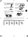 5
5
-
 6
6
-
 7
7
-
 8
8
-
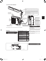 9
9
-
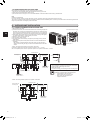 10
10
-
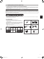 11
11
-
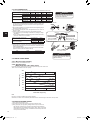 12
12
-
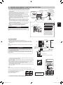 13
13
-
 14
14
-
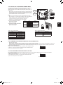 15
15
-
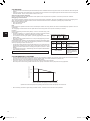 16
16
-
 17
17
-
 18
18
-
 19
19
-
 20
20
-
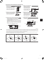 21
21
-
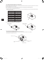 22
22
-
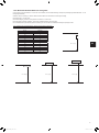 23
23
-
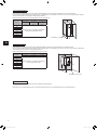 24
24
-
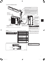 25
25
-
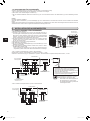 26
26
-
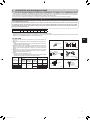 27
27
-
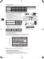 28
28
-
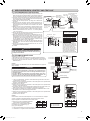 29
29
-
 30
30
-
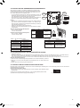 31
31
-
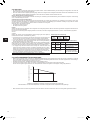 32
32
-
 33
33
-
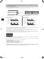 34
34
-
 35
35
-
 36
36
-
 37
37
-
 38
38
-
 39
39
-
 40
40
-
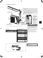 41
41
-
 42
42
-
 43
43
-
 44
44
-
 45
45
-
 46
46
-
 47
47
-
 48
48
-
 49
49
-
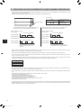 50
50
-
 51
51
-
 52
52
-
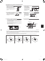 53
53
-
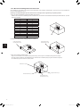 54
54
-
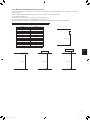 55
55
-
 56
56
-
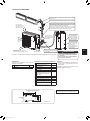 57
57
-
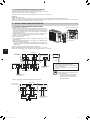 58
58
-
 59
59
-
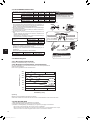 60
60
-
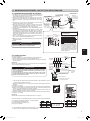 61
61
-
 62
62
-
 63
63
-
 64
64
-
 65
65
-
 66
66
-
 67
67
-
 68
68
-
 69
69
-
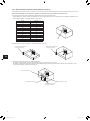 70
70
-
 71
71
-
 72
72
-
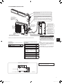 73
73
-
 74
74
-
 75
75
-
 76
76
-
 77
77
-
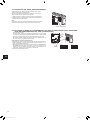 78
78
-
 79
79
-
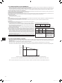 80
80
-
 81
81
-
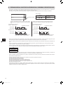 82
82
-
 83
83
-
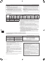 84
84
-
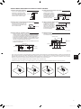 85
85
-
 86
86
-
 87
87
-
 88
88
-
 89
89
-
 90
90
-
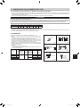 91
91
-
 92
92
-
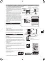 93
93
-
 94
94
-
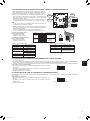 95
95
-
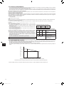 96
96
-
 97
97
-
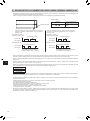 98
98
-
 99
99
-
 100
100
-
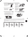 101
101
-
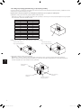 102
102
-
 103
103
-
 104
104
-
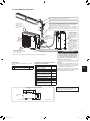 105
105
-
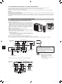 106
106
-
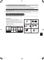 107
107
-
 108
108
-
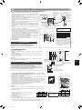 109
109
-
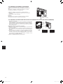 110
110
-
 111
111
-
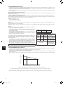 112
112
-
 113
113
-
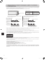 114
114
-
 115
115
-
 116
116
-
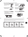 117
117
-
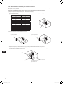 118
118
-
 119
119
-
 120
120
-
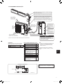 121
121
-
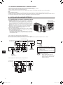 122
122
-
 123
123
-
 124
124
-
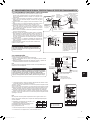 125
125
-
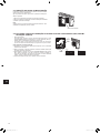 126
126
-
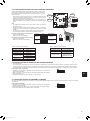 127
127
-
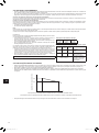 128
128
-
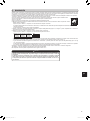 129
129
-
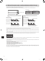 130
130
-
 131
131
-
 132
132
-
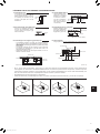 133
133
-
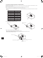 134
134
-
 135
135
-
 136
136
-
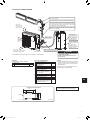 137
137
-
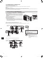 138
138
-
 139
139
-
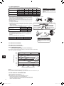 140
140
-
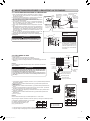 141
141
-
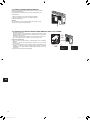 142
142
-
 143
143
-
 144
144
-
 145
145
-
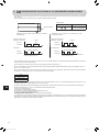 146
146
-
 147
147
-
 148
148
-
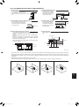 149
149
-
 150
150
-
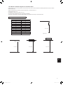 151
151
-
 152
152
-
 153
153
-
 154
154
-
 155
155
-
 156
156
-
 157
157
-
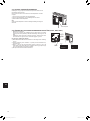 158
158
-
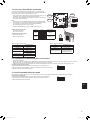 159
159
-
 160
160
-
 161
161
-
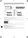 162
162
-
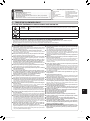 163
163
-
 164
164
-
 165
165
-
 166
166
-
 167
167
-
 168
168
-
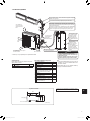 169
169
-
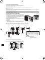 170
170
-
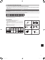 171
171
-
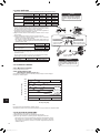 172
172
-
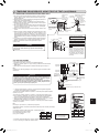 173
173
-
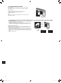 174
174
-
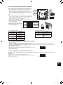 175
175
-
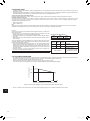 176
176
-
 177
177
-
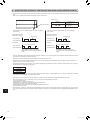 178
178
-
 179
179
-
 180
180
-
 181
181
-
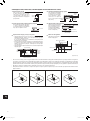 182
182
-
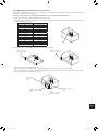 183
183
-
 184
184
-
 185
185
-
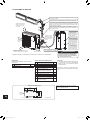 186
186
-
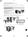 187
187
-
 188
188
-
 189
189
-
 190
190
-
 191
191
-
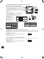 192
192
-
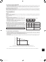 193
193
-
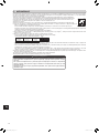 194
194
-
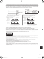 195
195
-
 196
196
-
 197
197
-
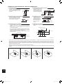 198
198
-
 199
199
-
 200
200
-
 201
201
-
 202
202
-
 203
203
-
 204
204
-
 205
205
-
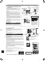 206
206
-
 207
207
-
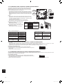 208
208
-
 209
209
-
 210
210
-
 211
211
-
 212
212
-
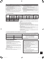 213
213
-
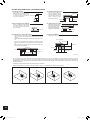 214
214
-
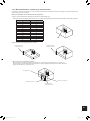 215
215
-
 216
216
-
 217
217
-
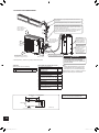 218
218
-
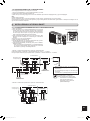 219
219
-
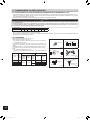 220
220
-
 221
221
-
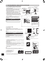 222
222
-
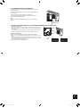 223
223
-
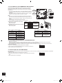 224
224
-
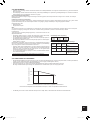 225
225
-
 226
226
-
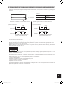 227
227
-
 228
228
-
 229
229
-
 230
230
-
 231
231
-
 232
232


Mitsubishi Electric PXZ-4F75VG Split-Type Air-Conditioner Manuel utilisateur
- Catégorie
- Climatiseurs split-system
- Taper
- Manuel utilisateur
dans d''autres langues
- italiano: Mitsubishi Electric PXZ-4F75VG Split-Type Air-Conditioner Manuale utente
- español: Mitsubishi Electric PXZ-4F75VG Split-Type Air-Conditioner Manual de usuario
- Deutsch: Mitsubishi Electric PXZ-4F75VG Split-Type Air-Conditioner Benutzerhandbuch
- português: Mitsubishi Electric PXZ-4F75VG Split-Type Air-Conditioner Manual do usuário
- dansk: Mitsubishi Electric PXZ-4F75VG Split-Type Air-Conditioner Brugermanual
- Türkçe: Mitsubishi Electric PXZ-4F75VG Split-Type Air-Conditioner Kullanım kılavuzu
Autres documents
-
LG PM05SP.NSJ Manuel utilisateur
-
LG MS07ET Le manuel du propriétaire
-
Panasonic CU2TZ50TBE Mode d'emploi
-
Panasonic CU2Z50TBE Mode d'emploi
-
Panasonic FZ 5 Le manuel du propriétaire
-
Panasonic CSPZ35VKE Mode d'emploi
-
Panasonic CSZ50XKEW Mode d'emploi
-
-
Panasonic CUUZ50WKE Le manuel du propriétaire
-
Panasonic CSXZ35VKEW Le manuel du propriétaire