Nilfisk CA60 20B 20IN ORB BASE Le manuel du propriétaire
- Catégorie
- Machine à plancher
- Taper
- Le manuel du propriétaire
Ce manuel convient également à

VS13039 01/2022 Rev. F
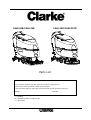
CA60 20B/CA60 24B CA60 20D/CA60 20TD
Instructions For Use - Original Instructions / Instrucciones de uso / Mode d’ emploi
This book has important information for the use and safe operation of this machine. Failure to read this book prior
to operating or attempting any service or maintenance procedure to your Clarke machine could result in injury to
you or to other personnel; damage to the machine or to other property could occur as well. You must have training
in the operation of this machine before using it. If your operator(s) cannot read this manual, have it explained fully
before attempting to operate this machine.
All directions given in this book are as seen from the operator’s position at the rear of the machine.
(1-24)
(25-48)
(49-72)
(73-108)
Parts List

INSTRUCTIONS FOR USE ENGLISH
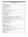
TABLE OF CONTENTS
INTRODUCTION .................................................................................................................................. 1
MANUAL CONTENT AND PURPOSE ........................................................................................................................1
HOW TO KEEP THIS MANUAL ..................................................................................................................................1
DECLARATION OF CONFORMITY ...........................................................................................................................1
ACCESSORIES AND MAINTENANCE ......................................................................................................................1
CHANGE AND IMPROVEMENT ................................................................................................................................1
SCOPE OF APPLICATION ...........................................................................................................................................1
MACHINE IDENTIFICATION DATA .........................................................................................................................1
TRANSPORT AND UNPACKING ...............................................................................................................................2
SAFETY .................................................................................................................................................. 2
VISIBLE SYMBOLS ON THE MACHINE ...................................................................................................................2
SYMBOLS THAT APPEAR ON THE INSTRUCTION FOR USE MANUAL ...........................................................2
GENERAL SAFETY INSTRUCTION ...........................................................................................................................3
MACHINE DESCRIPTION ................................................................................................................. 5
MACHINE STRUCTURE ..............................................................................................................................................5
CONTROL PANEL ........................................................................................................................................................6
DISPLAY WINDOW OF CHARGER INDICATON LIGHT .......................................................................................6
TECHNICAL PARAMETERS .......................................................................................................................................7
OPERATING GUIDE ............................................................................................................................ 8
BATTERY CHECK/SETTING ON A NEW MACHINE ..............................................................................................9
BATTERY INSTALLATION AND BATTERY TYPE SETTING (WET OR GEL/ AGM) ........................................9
BRUSH/PAD-HOLDER INSTALLATION AND UNINSTALLATION ....................................................................10
ADJUSTING THE BALANCE OF SQUEEGEE .........................................................................................................10
SOLUTION OR WASHING WATER TANK FILLING .............................................................................................11
DETERGENT TANK FILLING (FOR MACHINES WITH CHEMICAL MIXING SYSTEM) ................................11
MACHINE START AND STOP ..................................................................................................................................12
ADJUSTING THE LEVEL OF ORBITAL DECK(only for orbital machine) .............................................................12
MACHINE OPERATION (SCRUBBERING AND DRYING) ...................................................................................13
TANK EMPTYING ......................................................................................................................................................14
AFTER USING THE MACHINE .................................................................................................................................15
MACHINE LONG INACTIVITY ................................................................................................................................15
FIRST PERIOD OF USE ..............................................................................................................................................15
MAINTENANCE ................................................................................................................................. 16
SCHEDULED MAINTENANCE TABLE ...................................................................................................................16
BATTERY CHARGING ..............................................................................................................................................17
BRUSH/PAD CLEANING ...........................................................................................................................................18
SOLUTION FILTER CLEANING ...............................................................................................................................18
SQUEEGEE CLEANING .............................................................................................................................................19
SQUEEGEE BLADE CHECK AND REPLACEMENT ..............................................................................................20
TANK AND VACUUM GRID WITH FLOAT CLEANING, AND COVER GASKET CHECK ..............................21
DETERGENT TANK CLEANING ..............................................................................................................................22
MACHINE WORKING HOUR CHECK .....................................................................................................................22
FUSE CHECK/REPLACEMENT ................................................................................................................................23
ACCESSORIES/OPTIONS ..........................................................................................................................................24
TROUBLESHOOTING ....................................................................................................................... 24
SCRAPPING ......................................................................................................................................... 24

INSTRUCTIONS FOR USE ENGLISH
1
INTRODUCTION
NOTE
The numbers in brackets refer to the components shown in Machine Description chapter.
MANUAL CONTENT AND PURPOSE
The purpose of this Instruction for Use Manual is to provide the operator with necessary information to use the
machine properly and safely. It contains information about technical data, safety, operation, storage, maintenance,
spare parts and how to scrap it.
Before performing any procedure on the machine, no matter the operators and qualified technicians must read this
Manual carefully. Contact our company service center for any query about this manual or for any further information
is needed.
The operators must not perform procedures that should be done by qualified technicians. Our company will not be
answerable for damages coming from the non-observance of this prohibition.
HOW TO KEEP THIS MANUAL
The Manual must be kept near the machine, inside an adequate case, away from liquids and other substances that can
cause any damage to it.
DECLARATION OF CONFORMITY
Declaration of Conformity is supplied with the machine and certifies machine conformity with the law in force.
NOTE
The copies of the original declaration of conformity are provided together with the machine
documentation.
ACCESSORIES AND MAINTENANCE
All the necessary operation, maintenance and repair procedures must be performed by qualified personnel, or by our
company appointed service center. ONLY authorized spare parts and accessories should be used.
Contact our company customer service for any service or purchase of accessories or spare parts if necessary.
CHANGE AND IMPROVEMENT
We committed to continuous improvement of its products, the company reserves the right to the machine changes and
improvements without informing in additional.
SCOPE OF APPLICATION
The scrubber applies to commercial and industrial use. It is suitable for cleaning smooth and solid floor, operat-ing by
a qualified personnel in safety circumstance. It is not suitable for outdoor use or carpet or rough floor cleaning.
MACHINE IDENTIFICATION DATA
The machine serial number and model name are marked on the serial label.
This information is useful. Use the following table to write down the machine identification data when requiring
spare parts for the machine.
MACHINE MODEL......................................................................
MACHINE SERIAL NUMBER.....................................................

INSTRUCTIONS FOR USE ENGLISH
2
TRANSPORT AND UNPACKING
When the carrier delivers the machine, make sure the packaging and machine are both whole and undamaged. If any
damaged, make the carrier know the damage and before accepting the goods, reserve the right in compensation of the
damage.
Follow the instructions on packing strictly when unpacking the machine.
Check the package to ensure following items are included:
1. Technical documentations including Quick Start Guide manual, on-board charger manual if on-board charger is
equipped.
2. Charger cable if on-board charger is equipped.
3. Two fuses, the low power circuit fuse (5A) and the Brush release fuse (20A/5A).
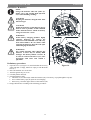
SAFETY
The following symbols indicate potentially dangerous situations. Always read this information carefully and take all
necessary precautions to safeguard people and property.
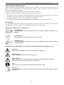
VISIBLE SYMBOLS ON THE MACHINE
WARNING!
Read all the instructions carefully before performing any operation on the machine.
WARNING!
Do not wash the machine with direct or pressurized water jets.
WARNING!
Do not use the machine on slopes with a gradient exceeding that is defined in the
specification.
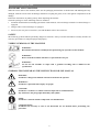
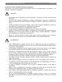
SYMBOLS THAT APPEAR ON THE INSTRUCTION FOR USE MANUAL
DANGER!
It indicates a dangerous situation with risk of death for the operator.
WARNING!
It indicates a potential risk of injury for people.
CAUTION!
It indicates a caution or a remark related to important or useful functions.
Pay attention to the paragraphs marked by this symbol.
NOTE
It indicates a remark related to important or useful functions.
CONSULTATION
It indicates the necessity to refer to the Instruction for Use manual before performing any
procedure.

INSTRUCTIONS FOR USE ENGLISH
3
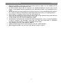
GENERAL SAFETY INSTRUCTION
Specific warnings and cautions to inform about potential damages to people and machine are shown below.
DANGER!
This machine must be operated by trained and authorized personnel according to guidance of the
manual.
Before performing any cleaning, maintenance, repair or replacement procedure, read all the
instructions carefully, ensure to turn the machine OFF and disconnect the battery connector.
Do not operate the machine near toxic, dangerous, flammable and/or explosive powders, liquids or
vapor. This machine is not suitable for collecting dangerous powders.
Do not wear jewels when working near electrical components.
Do not work under the lifted machine without supporting it with safety stands.
When using lead (WET) batteries, they may emit inflammable gas under normal use, must keep
sparks, flames, smoking materials and radiating, illuminating and burning items away from the
batteries.
When charging lead (WET) batteries, they may emit hydrogen gas which may cause explosive. Must
ensure the charging environment is well ventilated and away from naked flames.
WARNING!
Check the machine carefully before each use. Ensure that all the components have been well
assembled before use. Or it may causes damages to people and properties.
Before using the battery charger, ensure that the values of frequency and voltage indicated on the
machine serial number label match those of mains.
Never move the machine by pulling the battery charger cable. Do not let the cable through a closed
door, or winding on sharp edges or corners. Do not run the machine on the battery charger cable.
Keep the battery charger cable away from heated surfaces.
Do not charge the batteries if the battery charger cable or the plug are damaged.
To reduce the risk of fire, electric shock, or injury, make sure machine is off before leaving.
Use or store the machine indoors in dry conditions, it is not allowed for outdoor use.
The machine both storage and working temperature must be between 0 °C and +40 °C, the humidity
of air must be between 30% - 95%.
Do not use the machine on slopes with a gradient exceeding as specification show.
When using and handling floor cleaning detergents, follow the instructions on the labels of the
detergent bottles and wear suitable gloves and protections.
Use brushes and pads supplied with the machine or defined in the manual. Using other brushes or
pads could reduce safety.
In case of machine malfunctions, ensure that these are not due to lack of maintenance. If necessary,
request assistance from the authorized personnel or from an authorized Service Center.
Take all necessary precautions to prevent hair, jewels and loose clothes from being caught by the
machine moving parts.
Do not use the machine in particularly dusty areas.
Do not wash the machine with direct or pressured water jets, or with corrosive substances.
Do not bump into shelves or scaffoldings, especially where there is a risk of falling objects.
Do not lean liquid containers on the machine, use the relevant can holder.
To avoid damaging the floor, do not allow the brush/pad to operate while the machine is stationary.
In case of fire, use a dry powder fire extinguisher. Do not use liquid fire extinguishers.
Do not remove or modify the machine stickers.
Do not tamper with the machine safety guards and follow the ordinary maintenance instructions
scrupulously.
Pay attention during machine transportation when temperature is below freezing point. The water in
the recovery tank and in the hoses could freeze and cause seriously damage to the machine.
If spare parts need be replaced, order ORIGINAL spare parts from an Authorized Dealers or Retailers.

INSTRUCTIONS FOR USE ENGLISH
4
Return the machine to the Service Center if it doesn’t work as usual or it is in condition such as
damaged, placed outdoors, dropped into water.
To ensure machine proper and safe operation, the scheduled maintenance shown in the relevant
chapter of this Manual, must be performed by the authorized personnel or an authorized Service
Center.
The machine must be properly disposed of, because the presence of toxic-harmful materials (batteries,
etc.), which are subject to standards that require disposal in special centers (see Scrapping chapter).
This machine as a cleaning tool only, not for any other purpose use.
Always keep the openings free from dust, hairs and any other foreign material which could reduce the
air flow. Do not use the machine if the openings are clogged.
Use the machine only where a proper lighting is provided.
This machine is not intended for use by persons with reduced physical, sensory or mental capabilities,
or lack of experience and knowledge, unless they have been given supervision or instruction
concerning use of the machine by a person responsible for their safety.
Close attention is necessary when used near children.
Children should be supervised to ensure that they do not play with the machine.
While using this machine, take care not to cause damage to people or objects.

INSTRUCTIONS FOR USE ENGLISH
5
29 32
1 2 3
25
24
23
21
20
19
18 17 16 15 11 14 13 11
4
5
6
7
8
9
10
30
28
27
26
10b
10a
31
33
35
34
12
22
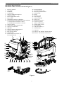
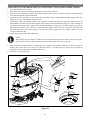
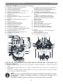
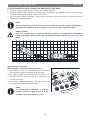
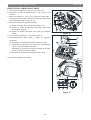
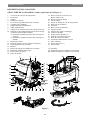
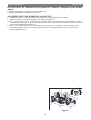
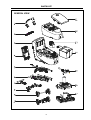
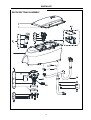
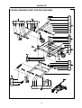
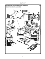
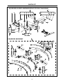
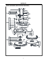
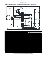
MACHINE DESCRIPTION
MACHINE STRUCTURE (as shown in Figure 1)
1. Recovery tank lid
2. Can holder
3. Handlebar
4. Control panel
5. Squeegee lifting/lowering lever
6. Garden coupling
7. Power supply cable holder
8. Power cable
9. Solution drain and level check hose
10. Deck lifting/lowering pedal(only for disc machine)
a) Pedal position when deck is lifted
b) Pedal position when deck is lowered
11. Squeegee knobs
12. Serial number plate/technical data
13. Squeegee vacuum hose
14. Squeegee
15. Squeegee balance adjusting knob
16. Solution/clean water tap
17. Rear steering wheels
18. Solution filter
19. Front wheels on fixed axle (A).
Driving wheels (B)
20. Brush/pad-holder
21. Brush/pad-holder deck
22. Recovery water drain hose
23. Solution tank
24. Hinge
25. Recovery tank
26. Filter support
27. Filler hose holder
28. Filter cover
29. Baseboard cleaner(*)
30. Tank cover gasket
31. Debris collection box
32. Splash guard 510mm
33. Float ball filter
34. Mop and trash kit (*)
35. Solenoid valve
(*): Optional
(A): Only for disc machine without traction
(B): Only for disc machine with traction
Figure 1

INSTRUCTIONS FOR USE ENGLISH
6
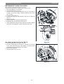
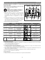
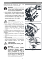
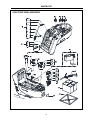
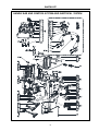
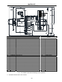
CONTROL PANEL (as shown in Figure 2)
36. Machine backward switch (B)
37. Tank safety cable
38. Battery connector (red).
39. Detergent tank filler plug (**)
40. Detergent tank (**)
41. Reference table for detergent proportioning (**)
42. Detergent pump (**)
43. Detergent tank - pump connecting hose (**)
44. Detergent feed hose (**)
45. Batteries
46. Battery caps
47. Flow increase switch
48. Flow decrease switch
49. Solution flow indicator
50. Safe switch
51. Discharged battery warning light (red)
52. Semi-discharged battery warning light (yellow)
53. Charged battery warning light (green)
54. Ignition key (0 - I)
55. Detergent flow control knob (**)
56. Speed adjuster (B)
57. Hour meter
58. •Brush/pad-holder release switch(only for disc
machine)
•Extra pressure active(only for orbital machine)
59. Vacuum system switch
60. •Brush/pad-holder and vacuum system
switch(only for disc machine)
•Pad deck moving up/down and Brush/pad-
holder and vacuum system switch(only for
orbital machine)
61. Charging red LED
62. Charging yellow LED
63. Charging green LED
64. Security cover of charging jack
65. Overload protector of brush/pad
66. Overload protector of traction (B)
67. Overload protector of vacuum
(*): Optional
(**): Only for machines with Chemical Mixing
System (optional)
(A): Only for machine without traction
(B): Only for machine with traction
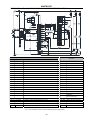
DISPLAY WINDOW OF CHARGER INDICATON LIGHT (as shown in Figure 2)
1. At the beginning of charging, the red LED (61) of charger normally on. It is the first stage of charging.
2. After charging some time, the red LED (61) turns off, the yellow LED (62) turns on, this is the second stage of
charging.
3. After charging finish, the yellow LED (62) off, the green LED (63) turns on to indicate that the battery is fully
charged.
NOTE
When charging, if the yellow LED (62) of charger is on, it may be caused by: Battery and charger
does not match, battery is not connected well, or output is short-circuited.
The red LED of charger flashing may be caused by charger internal short circuit.
52 5351 5050
49
48
47
60 59 58 57
61 62 63
67 66 65 64
54
55
56
45
46
37
38
39
40
41
42
43
44
36
BRUSHTRACTION
VACUUM

INSTRUCTIONS FOR USE ENGLISH
7
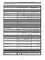
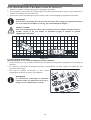
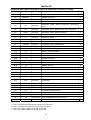
TECHNICAL PARAMETERS
MODEL Units CA60 24B CA60 20B CA60 20D CA60 20TD
Packing dimensions (Lx W
x H) mm/Inches
(1370x700x1300mm)
/(54x28x52 Inches)
(1370x600x1300mm)/
(54x24x5
2
Inches
)
Machine height
mm/Inches
1080
mm/42.5
Inches
Machine length
mm/Inches
1260mm/50
Inches
Machine width (without
squeegee)
mm/Inches
650mm/26 Inches
550mm/22 Inches
Machine weight with
empty tanks (without
batteries)
Kg/Lbs. 124 Kg/273Lbs. 122 Kg/268Lbs.
91 Kg/200Lbs.
97 Kg/213Lbs.
Gross vehicle weight
(GVW)
Kg/Lbs. 243 Kg/535Lbs. 241 Kg/530Lbs.
208 Kg/458Lbs.
214 Kg/471Lbs.
Shipping weight
Kg/Lbs.
170
Kg/37
4
Lbs.
154
Kg/3
39
Lbs.
121
Kg/26
6
Lbs.
127
Kg/280Lbs.
Solution t
ank capacity
L / Gal
61 L / 16 Gal.
Recovery tank capacity
L / Gal
61 L / 16 Gal.
Vacuum motor power
Watt / HP
350 W / 0.47 HP
Vacuum capacity mm/In of
H2O
1200 mm / 47.2 Inches H2O
Climbing capacity (Max)
%
grade
2%
Front wheel diameter
mm/Inches
200 mm / 8 Inches
Rear wheel diameter
mm/Inches
76 mm / 3 Inches
Sound level
dB (A)
69 +/
-
3 dB (A)
Solution/ Flow(Max)
L / Gal per
minute
(0.
4
/
0.8
/1.
4
/2.2)
Liters
(0.
11
/0.
21
/0.
37
/0.6) Gallons
(0.7/1.2/1.7/2.2) Liters
(0.2/0.3/
0.45/0.6) Gallons
Working width mm/Inches
610mm/24 Inches
510 mm / 20
Inches
530mm/21 Inches
Squeegee width
mm/Inches
760mm/30
Inches
Brush/pad diameter mm/Inches
(610x360mm) (24x14
Inches
)
(510x360mm)
(20
x14
Inches
)
(530mm/21Inches)/(508mm/20In
ches)
B
rush motor power
Watt / HP
750 Watt / 1.0 HP
450 Watt / 0.6 H
P
Brush speed
Rpm
2200
150
Brush/pad pressure(Max)
Kg/Lbs.
40
-
50 Kg / 88
-
110 Lbs.
27
Kg /60 Lbs.
23
Kg /51 Lbs.
Drive motor power
Watt / HP
250 W / 0.33 HP
/
150 W / 0.2 H
P
Working speed Km / Miles
per hour 0-3.2 Km / 0 - 2 Miles per hour /
0 - 4.0 Km / 0 -
2.5 Miles per
hour
Forward speed Km / Miles
per hour 0 - 4.0 Km / 0 - 2.5 Miles per hour /
0 - 4.0 Km / 0 -
2.5 Miles per
hour
Reverse speed Km / Miles
per hour 0 - 2.0 Km / 0 - 1.25 miles per hour
/
0 - 2.0 Km / 0 -
1.25 miles per
hour
Handle Vibration
Level(Max)
m/S² 2.5 2.5
Voltage
Volts
24
Volts
Battery(Optional)
Amp/hour
105/130 WET, 105/140 AGM C20
Battery charger
Volts/Amps
24 Volt/13 Amp
Battery compartment
size (L x W x H
)
mm/Inches
(350 x 350 x 300) mm / 13.8 x 13.8 x 11.8) Inches

INSTRUCTIONS FOR USE ENGLISH
8
OPERATING GUIDE
WARNING!
On some points of the machine there are some adhesive plates indicating:
— DANGER!
— WARNING!
— CAUTION!
— CONSULTATION
While reading this Manual, the operator must pay particular attention to the symbols shown on the plates. Do
not cover these plates for any reason and immediately replace them if damaged.
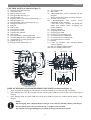
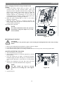
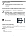
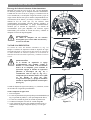
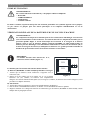
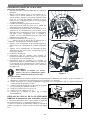
BATTERY CHECK/SETTING ON A NEW MACHINE
WARNING!
The electric components of the machine can be seriously damaged if the batteries are either
improperly installed or connected. The batteries must be installed by qualified personnel only. Set
the function electronic board and the built-in battery charger according to the type of batteries
used (WET or GEL/AGM batteries).Check the batteries for damage before installation.
Disconnect the battery connector (38) and the battery charger plug (8). Handle the batteries with
great care. Install the battery terminal protection caps supplied with the machine.
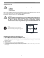
NOTE
The machine requires two 12 V batteries,
connected according to the diagram (Figure. 3).
The machine can be supplied in one of the following modes:
A) Batteries (WET or GEL/ AGM) already installed and charged
1. Check that the batteries are connected to the machine with the connector (38).
2. Insert the ignition key (54) and turn it to "I". If the green warning light (53) turns on, the batteries are fully
charged. If the yellow (52) or red warning light (51) turns on, the batteries must be charged (see the procedure in
Maintenance chapter).
B) Without batteries
1. Buy appropriate batteries (see the Technical Data paragraph).
2. For battery choice and installation, apply to qualified battery Retailers.
3. Set the machine and the battery charger according to the type of batteries (WET or GEL/ AGM), as shown in the
next paragraph.
Figure 3
12V
+
-
12V
+-

INSTRUCTIONS FOR USE ENGLISH
9
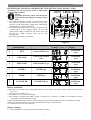
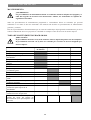
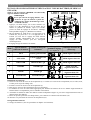
BATTERY INSTALLATION AND BATTERY TYPE SETTING (WET OR GEL/ AGM)
According to the type of batteries (WET or GEL/AGM),
set the machine as follows:
NOTE
Regarding the factory setting, learn the battery
type from boot time display according to above
table
1. Press both the buttons (A, Figure. 4) and (B) at the same
time, Insert the ignition key (D) and turn on the power,
after 0.5 second, enter battery setting mode. LED display
during setting( C) ,Release the buttons.
2. The mode can be shift from 0 to 5 by pressing button (B),
or shift from 5 to 0 by pressing button (A). After the
battery mode setting is completed, turn off the power (D)
and the new setting of battery mode can be saved
automatically.
3. The battery type setting is completed.
Battery installation
4. Open the recovery tank cover (1) and check that the recovery tank (25) is empty; otherwise empty it with the drain
hose. (22)
5. Close the recovery tank cover (1).
6. Overturn the recovery tank (25) carefully.
7. The machine is supplied with cables suitable to install 2×12 V batteries. Carefully put the batteries into the
compartment, then install them correctly.
8. Route and install the battery cable as shown in (Figure3), then carefully tighten the nut on each battery terminal.
9. Place the protection cap on each terminal, then connect the battery connector (38).
10. Carefully lower the recovery tank (25).
Battery charging
11. Charge the batteries. (See procedures in maintenance chapter).
Mode
Battery type/Battery
manufacturer
Battery charging curve LED display during
setting( C, Figure. 4)
Boot time
display
0 WET General WET curve LED1 blink
twice
1 GEL/AGM General GEL/AGM
curve
LED2 blink
twice
2 DISCOVER DISCOVER EV gel LED3 blink
twice
3 OPTIMA OPTIMA gel
Both LED1 and
LED2 blink
twice
4 EXIDE EXIDE gel
Both LED1 and
LED3 blink
twice
5 FULLRIVER FULLRIVER gel
Both LED2 and
LED3 blink
twice
A
LED1 LED2 LED3
BCD
Figure 4

INSTRUCTIONS FOR USE ENGLISH
10
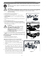
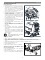
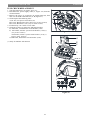
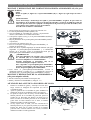
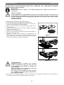
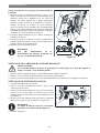
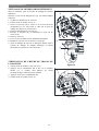
BRUSH/PAD-HOLDER INSTALLATION AND UNINSTALLATION (only for disc machine)
NOTE
Install either the brush (A, Figure 5) or pad-holder (B and C, Figure5) according to the type of
floor to be cleaned.
CAUTION!
Before installation or uninstallation of brush or pad-holder, make sure all the switches on machine
are in off position and lifting up the squeegee from the floor. The operator must be equipped with
suitable personnel protection devices such as gloves to reduce the risk of accidents.
Proceed as following:
1. Insert the ignition key (54) and turn it to "O".
2. Lift the deck by pressing the pedal (10).
3. If equipped, turn the speed adjuster (56) to idle by turning it
counter-clockwise.
4. Place the brushes (A, Figure. 5) or the pad-holder (B) under the
deck (21).
5. Lower the deck on the brushes/pad-holders by pressing the pedal
(10).
6. Turn the ignition key (54) to "I".
7. Press the Brush/pad-holder and vacuum system switch (60).
8. Press one of the safe switch (50) to engage the brush/pad-holder,
then release it. If necessary, repeat the procedure until the
brushes/pad-holders are engaged.
9. To remove the brush/pad-holder lift the deck by pressing the
pedal (10), then press the switch (58),the brush/pad-holder will be
remove.
PAD INSTALLATION AND UNINSTALLATION (only
for orbital machine)
1. Lift the deck by pressing the switch (60) .
2. Install and uninstall the pad (A, Figure. 5.1)
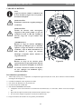
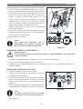
ADJUSTING THE BALANCE OF SQUEEGEE
1. Install the squeegee and screw up the nut (H), then
connect the vacuum hose (G) to the squeegee.
2. Adjust the squeegee by squeegee adjusting handle (A,
Figure 6).
a) If there is gap between the ground and middle section of
rear squeegee blade (B), adjust the knob (A) in
counterclockwise direction (F) until all section of rear
squeegee blade good contact with ground, the front blade
touch the ground slightly.
b) If there is gap between the ground and both end section of
rear blade(C and D), adjust the knob (A) in clockwise
direction (E) until all section of rear blade good contact
with the ground, the front blade touch the ground slightly.
WARNING!
(Only for machine with traction): Turn the
speed adjuster (56) counter-clockwise to drive
the machine at the minimum speed.
Slightly press the safe switch (50), otherwise
the machine starts to move.
To engage the safe switch (50) which turns on
the brush/pad-holder motor.
Figure 5
A
C
B
Figure 5.1
A
A
Figure 6
EF
A
D
B
C
H
H
G

INSTRUCTIONS FOR USE ENGLISH
11
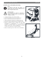
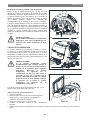
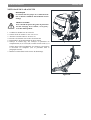
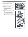
SOLUTION OR WASHING WATER TANK FILLING
NOTE
If the machine is equipped with Chemical
Mixing System (optional) the tank must be
filled with clean water, otherwise the tank
can be filled with solution.
1. Open the filler neck (B, Figure.7).
2. (For machines without Chemical Mixing System) Use the
front filler neck (B) and the rear filler neck (H) to fill the
tank (D) with a solution suitable for the work to be
performed. Refill to the reference mark “1” of the level
check hose (H). Always follow the dilution instructions on
the label of the chemical product used to prepare the
solution. The solution temperature must not exceed +104°F
(+40°C).
WARNING!
Use only low-foam and non-flammable
detergents, intended for automatic scrubber
applications.
3. (For machines with Chemical Mixing System) Fill the tank
(D) with clean water by using the filler neck (B) and the
rear filler neck (H). Refill to the reference mark “1” of the
level check hose (H). The water temperature must not
exceed +104°F (+40°C).
DETERGENT TANK FILLING (FOR MACHINES
WITH CHEMICAL MIXING SYSTEM)
1. Open the cover (E) and check that the recovery tank (F) is
empty, otherwise empty it with the drain hose (G).
2. Carefully overturn the recovery tank (A, Figure. 8).
3. Open the cap (B).
4. Replace or fill the jug (C) with any standard gallon
container of detergent suitable for the work to be performed
(highly concentrated detergents). Do not fill the detergent
tank completely, leave a few centimeters from the edge.
WARNING!
Use only low-foam and non-flammable
detergents, intended for automatic scrubber
applications.
NOTE
To install a new jug container, determine the
cap size and if it is the smaller cap, remove
the reducing adapter from the hose cap (B).
Insert the suction tube into the jug (C).
Pushdown firmly on the cap (B) and twist at
the same time to put the cap back onto the jug
(C). In case of new system, system emptied for
cleaning, etc., wait for the hoses to fill up,
before starting the Chemical Mixing System.
Figure
8
Figure 7
A
B
C
B
D
H
G
A
EF

INSTRUCTIONS FOR USE ENGLISH
12
Figure 9.1
B
B
A
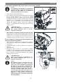
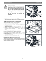
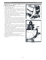
MACHINE START AND STOP
Starting the machine
1. Prepare the machine as shown in the previous paragraph.
2. Insert the ignition key (A, Figure. 9) and turn it to "I".
Check that the green warning light (B) turns on (charged
battery). If the yellow (C) or red warning light (D) turns
on, turn the ignition key back to “0” and charge the
batteries (see the procedure in Maintenance chapter).
3. Drive the machine to the working area:
•By pushing it with the hands on the handlebar (E) (only
for machine without traction).
•By pushing it with the hands on the handlebar (E) and
pressing the switch (F) to move forward, or pressing the
switch (F) together with the switch (G) to move backward
(only for machine with traction). The forward speed can
be adjusted with the adjuster (H).
4. Lower the squeegee (I) with the lever (J).
5. Lower the brush/pad-holder deck (K) by lifting the pedal
(L). (only for disc machine)
6. Press the brush/pad-holder switch (M) and the vacuum
system switch (N).
7. Press the washing water flow control switches (O) as
necessary, depending on the type of cleaning to be
performed.
8. Start cleaning:
•(only for machine without traction) by pushing the
machine with the hands on the handlebar (E) and pressing
the switch (F).
•(only for machine with traction) by pushing the machine
with the hands on the handlebar (E) and by pressing the
switch (F). If necessary, the forward speed can be adjusted
with the adjuster (H).
NOTE
To move the machine forward, press either
the left or right switch (F) or both.
Stopping the machine
9. Stop the machine by using the handlebar (E) (only for
machine without traction). Stop the machine by releasing the switches (F) (only for machine with traction).
10. Stop the brushes and the vacuum system by pressing the switch (M). The vacuum system stops after a few
seconds.
11. Lift the brush/pad-holder deck (K) by pressing the pedal (L). (only for disc machine)
12. Lift the squeegee (I) with the lever (J).
13. Turn the ignition key (A) to "0".
14. Make sure that the machine cannot move independently.
ADJUSTING THE LEVEL OF ORBITAL DECK
(only for orbital machine)
1. Lower the brush/pad-holder deck by press the brush/pad-
holder switch (M, Figure. 9)
2. Adjust the level of orbital deck by adjusting handle (A,
Figure 9.1) . made the bubble in the middle (B, Figure 9.1).
Figure 9
GD C B A
O
E
H
M N
FF
J
L
K
I

INSTRUCTIONS FOR USE ENGLISH
13
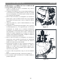
MACHINE OPERATION (SCRUBBERING AND DRYING)
1. Start the machine as shown in previous paragraphs.
2. While keeping both hands on the handlebar press the safety switch (F, Figure. 9), then maneuver the machine and
start scrubbing/drying the floor.
3. If necessary, stop the machine then adjust squeegee according to section “Adjusting balance of squeegee”.
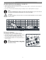
NOTE
For correct scrubbing/drying of floors at the sides of the walls, Suggests to go near the walls with
the right side of the machine (A and B, Figure. 10) as shown in the figure.
CAUTION!
To avoid any damage to the floor surface, turn off the brushes/pad-holders when the machine
stops in one place.
Detergent flow adjustment
(For machines with Chemical Mixing System)
1. Turn the knob (A, Figure. 11) clockwise or counter-clockwise
to increase or decrease the detergent concentration.
2. The average detergent concentration values, matching the 4
colored areas of the scale (B), are shown in the figure.
3. To set the detergent quantity to zero, fully turn the knob (A)
counter-clockwise.
NOTE
The detergent concentration is kept constant
even if the washing water flow is changed with
the switches (C) or (D).
Figure 10
A
B
Figure 11
A
B
2,5%
1,5%
0,75%
0,4%
C
D

INSTRUCTIONS FOR USE ENGLISH
14
Battery discharge during operation
Until the green warning light (A, Figure. 12) stays on, the
batteries allow the machine to work normally. When the green
warning light (A) turns off, and the yellow warning light (B)
turns on, it is advisable to charge the batteries, because the
remaining charge will last for a few minutes (depending on
battery characteristics and work to be performed). When the
red warning light (C) turns on, batteries are fully discharged.
After a few seconds, the brush/pad-holder is automatically
tuned off, while (only for machine with traction) the drive
system stay on, to finish drying the floor and drive the machine
to the appointed recharging area.
CAUTION!
Do not use the machine with discharged
batteries, to avoid damaging the batteries and
reducing the battery life.
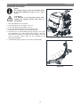
TANK EMPTYING
An automatic float shut-off system (A, Figure. 13) blocks the
vacuum system when the recovery water tank (B) is full. The
vacuum system deactivation is signaled by a sudden increase in
the vacuum system motor noise frequency, also the floor has
not dried.
CAUTION!
If the vacuum system turns off accidentally
(for example, when the float is activated
because of a sudden machine movement), to
resume the operation: turn off the vacuum
system by pressing the switch (D, Figure. 12),
then open the cover (C, Figure. 13) and check
that the float inside the grid (A) has gone
down to the water level. Then close the cover
(C) and turn on the vacuum system by
pressing the switch (D, Figure. 12).
When the recovery water tank (B, Figure. 13) is full, empty it
according to the following procedure.
Recovery water tank emptying
1. Stop the machine.
2. Lift the brush/pad-holder deck (E, Figure.12) by pressing
the pedal (F). (only for disc machine)
3. Lift the squeegee (G) with the lever (H).
4. Drive the machine to the appointed disposal area.
5. Empty the recovery water tank with the hose (I). Then, rinse
the tank (B, Figure. 13) with clean water.
Figure 12
Figure 13
I
C B A
D
H
F
E
G
C
B
A

INSTRUCTIONS FOR USE ENGLISH
15
CAUTION!
When draining the wastewater, the vacuum
tube for waste must be folded (A, Figure.
14) and lowered to a lower position (B,
Figure. 14), and then open the lid of the
vacuum tube for waste to drain the water.
Do not make the outlet of the vacuum tube
for waste face upward to drain the water
vertically. This is to avoid wastewater
spilling onto the operator.
6. Perform steps 1 to 4.
Solution/clean water tank emptying
7. Empty the solution tank with the hose (A, Figure. 15). After
working, rinse the tank with clean water.
AFTER USING THE MACHINE
After working, before leaving the machine:
1. Remove the brushes/pad-holders.
2. Empty the tanks (B and C, Figure. 15) as shown in the
previous paragraph.
3. Perform the daily maintenance procedures (see the
Maintenance chapter).
4. Store the machine in a clean and dry place, with the brushes/
pad-holders and the squeegee lifted or removed.
MACHINE LONG INACTIVITY
If the machine is not going to be used for more than 30 days,
proceed as follows:
1. Perform the procedures shown in After Using the machine
paragraph.
2. Disconnect the battery connector (38).
FIRST PERIOD OF USE
After the first 8 hours, check the machine fastening and
connecting parts for proper tightening and check the visible
parts for wear and leakage.
Figure 15
Figure 14
A
C
B
D
A
B

INSTRUCTIONS FOR USE ENGLISH
16
MAINTENANCE
WARNING!
Maintenance procedures must be performed after the machine is turned off and the battery
charger cable is disconnected. In addition, carefully read the safety chapters in the manual.
All scheduled or extraordinary maintenance procedures must be performed by qualified personnel or an authorized
Service Center. This manual only describes the general and common maintenance procedures.
For other maintenance procedures that are not in below maintenance schedule table, please refer to the Service
Manual that can be consulted at any our company Service Center.
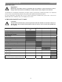
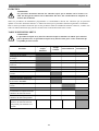
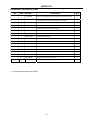
SCHEDULED MAINTENANCE TABLE
CAUTION!
The procedure marked with (1) must be performed when the machine is used after 9 hours for
the first time. The procedure marked with (2) must be done by Service Center that qualified by
our company.
Procedure Daily, after each
use
Weekly semiannually Yearly
Battery charging
Squeegee cleaning
Brush/Pad-holder cleaning
Tank cleaning
Tank sealing strip inspection
Float ball filter cleaning
Pad cleaning
Squeegee blade check and replacement
Cleaning water filter cleaning
Suction filter cleaning
WET battery fluid level check
Screw and nut tightness inspection (1)
Lower Isolator (2)
Brush/Pad-holder carbon brush check or
replacement
(2)
Suction motor carbon brush check or
replacement
(2)
Drive system motor carbon brush check or
replacement (only for machine with traction)
(2)

INSTRUCTIONS FOR USE ENGLISH
17
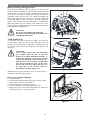
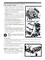
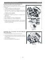
BATTERY CHARGING
NOTE
Charge the batteries when the yellow (G,
Figure. 16) or red warning light (H) turns
on, or when finishing cleaning.
CAUTION!
Keeping the batteries charged make their
life last longer.
CAUTION!
When the batteries are discharged, charge
them as soon as possible, as that condition
makes their life shorter. Check for battery
charge at least once a week.
WARNING!
WET battery charging produces highly
explosive hydrogen gas. Charge the
batteries in well-ventilated areas and away
from naked flames. Do not smoke while
charging the batteries. Keep the tank open
while charging the batteries.
WARNING!
Pay careful attention when charging the
batteries as there may be battery fluid
leakages. The battery fluid is corrosive. If
it comes in contact with skin or eyes, rinse
thoroughly with water and consult a
physician.
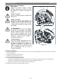
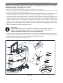
Preliminary procedures
1. Open the cover (A, Figure. 16) and check that the recovery
water tank (B) is empty, otherwise empty it with the drain
hose (C).
2. Drive the machine on a level floor.
3. Turn the ignition key (F) to "0".
4. Carefully lift the tank (B).
5. For WET batteries only:
•Check the level of electrolyte inside the batteries (D); if necessary, top up through the caps (E).
•Leave all the battery caps (E) open for next charging.
•If necessary, clean the upper surface of the batteries (D).
6. Charge the batteries according to the following procedure.
Figure 16
A
B
C
H G F
D
E

INSTRUCTIONS FOR USE ENGLISH
18
Battery charging with battery charger installed on the
machine
7. Connect the battery charger cable (A, Figure. 17) to the
electrical mains (G) (the electrical mains voltage and
frequency must be compatible with the battery charger values
shown on the machine serial number plate (F). When the
battery charger is connected to the electrical mains, all
machine functions are automatically cut off. If the red
warning light (B) on the battery charger control panel stays
on, the battery charger is charging the batteries.
8. When the green warning light (C) turns on, the battery
charging is completed.
9. When the battery charging is completed, disconnect the
battery charger cable (A) from the electrical mains (G) and
wind it round its housing (D).
10. Carefully lower the tank.
NOTE
For further information about the operation
of the battery charger (E, Figure. 17), see the
relevant Manual.
BRUSH/PAD CLEANING
CAUTION!
It is advisable to use protective gloves when cleaning the brush/pad because there may be sharp
debris.
1. Remove the brush/pad from the machine, as shown in the Use chapter.
2. Clean and wash the brush/pad with water and detergent.
3. Check that the brushes/pads are in working condition and not excessively worn; if necessary replace them.
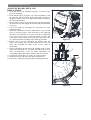
SOLUTION FILTER CLEANING
1. Drive the machine on a level floor.
2. Ensure that the machine is off and the ignition key (54) has
been removed.
3. Close the solution tap (A, Figure. 18) under the machine,
behind the right rear wheel. The tap (A) is closed when it is
on the position (B) and it is open when it is on the position
(C).
4. Remove the transparent cover (D), then remove the filter
strainer (E). Clean and install them on the support (F).
NOTE
The filter strainer (E) must be correctly
positioned on the housing (H) of the support
(F).
5. Open the tap (A).
Figure 17
F
G
VACUUM TRACTION BRUSH
C
B
E
D
A
Figure 18
H
E
D
E
G
F
B
C
A
La page est en cours de chargement...
La page est en cours de chargement...
La page est en cours de chargement...
La page est en cours de chargement...
La page est en cours de chargement...
La page est en cours de chargement...
La page est en cours de chargement...
La page est en cours de chargement...
La page est en cours de chargement...
La page est en cours de chargement...
La page est en cours de chargement...
La page est en cours de chargement...
La page est en cours de chargement...
La page est en cours de chargement...
La page est en cours de chargement...
La page est en cours de chargement...
La page est en cours de chargement...
La page est en cours de chargement...
La page est en cours de chargement...
La page est en cours de chargement...
La page est en cours de chargement...
La page est en cours de chargement...
La page est en cours de chargement...
La page est en cours de chargement...
La page est en cours de chargement...
La page est en cours de chargement...
La page est en cours de chargement...
La page est en cours de chargement...
La page est en cours de chargement...
La page est en cours de chargement...
La page est en cours de chargement...
La page est en cours de chargement...
La page est en cours de chargement...
La page est en cours de chargement...
La page est en cours de chargement...
La page est en cours de chargement...
La page est en cours de chargement...
La page est en cours de chargement...
La page est en cours de chargement...
La page est en cours de chargement...
La page est en cours de chargement...
La page est en cours de chargement...
La page est en cours de chargement...
La page est en cours de chargement...
La page est en cours de chargement...
La page est en cours de chargement...
La page est en cours de chargement...
La page est en cours de chargement...
La page est en cours de chargement...
La page est en cours de chargement...
La page est en cours de chargement...
La page est en cours de chargement...
La page est en cours de chargement...
La page est en cours de chargement...
La page est en cours de chargement...
La page est en cours de chargement...
La page est en cours de chargement...
La page est en cours de chargement...
La page est en cours de chargement...
La page est en cours de chargement...
La page est en cours de chargement...
La page est en cours de chargement...
La page est en cours de chargement...
La page est en cours de chargement...
La page est en cours de chargement...
La page est en cours de chargement...
La page est en cours de chargement...
La page est en cours de chargement...
La page est en cours de chargement...
La page est en cours de chargement...
La page est en cours de chargement...
La page est en cours de chargement...
La page est en cours de chargement...
La page est en cours de chargement...
La page est en cours de chargement...
La page est en cours de chargement...
La page est en cours de chargement...
La page est en cours de chargement...
La page est en cours de chargement...
La page est en cours de chargement...
La page est en cours de chargement...
La page est en cours de chargement...
La page est en cours de chargement...
La page est en cours de chargement...
La page est en cours de chargement...
La page est en cours de chargement...
La page est en cours de chargement...
La page est en cours de chargement...
La page est en cours de chargement...
La page est en cours de chargement...
La page est en cours de chargement...
La page est en cours de chargement...
La page est en cours de chargement...
La page est en cours de chargement...
La page est en cours de chargement...
-
 1
1
-
 2
2
-
 3
3
-
 4
4
-
 5
5
-
 6
6
-
 7
7
-
 8
8
-
 9
9
-
 10
10
-
 11
11
-
 12
12
-
 13
13
-
 14
14
-
 15
15
-
 16
16
-
 17
17
-
 18
18
-
 19
19
-
 20
20
-
 21
21
-
 22
22
-
 23
23
-
 24
24
-
 25
25
-
 26
26
-
 27
27
-
 28
28
-
 29
29
-
 30
30
-
 31
31
-
 32
32
-
 33
33
-
 34
34
-
 35
35
-
 36
36
-
 37
37
-
 38
38
-
 39
39
-
 40
40
-
 41
41
-
 42
42
-
 43
43
-
 44
44
-
 45
45
-
 46
46
-
 47
47
-
 48
48
-
 49
49
-
 50
50
-
 51
51
-
 52
52
-
 53
53
-
 54
54
-
 55
55
-
 56
56
-
 57
57
-
 58
58
-
 59
59
-
 60
60
-
 61
61
-
 62
62
-
 63
63
-
 64
64
-
 65
65
-
 66
66
-
 67
67
-
 68
68
-
 69
69
-
 70
70
-
 71
71
-
 72
72
-
 73
73
-
 74
74
-
 75
75
-
 76
76
-
 77
77
-
 78
78
-
 79
79
-
 80
80
-
 81
81
-
 82
82
-
 83
83
-
 84
84
-
 85
85
-
 86
86
-
 87
87
-
 88
88
-
 89
89
-
 90
90
-
 91
91
-
 92
92
-
 93
93
-
 94
94
-
 95
95
-
 96
96
-
 97
97
-
 98
98
-
 99
99
-
 100
100
-
 101
101
-
 102
102
-
 103
103
-
 104
104
-
 105
105
-
 106
106
-
 107
107
-
 108
108
-
 109
109
-
 110
110
-
 111
111
-
 112
112
-
 113
113
-
 114
114
-
 115
115


Nilfisk CA60 20B 20IN ORB BASE Le manuel du propriétaire
- Catégorie
- Machine à plancher
- Taper
- Le manuel du propriétaire
- Ce manuel convient également à
dans d''autres langues
Documents connexes
Autres documents
-
Windsor Chariot 3 iScrub 26 Le manuel du propriétaire
-
Windsor Chariot 3 iScrub 26 10061500 Operating Instructions Manual
-
Windsor Chariot 2 iScrub 20 Deluxe Le manuel du propriétaire
-
Clarke FOCUS II Micro Rider Mode d'emploi
-
-
Nilfisk-ALTO SCRUBTEC R 471C Manuel utilisateur
-
-
-
Hoover CH80100 Manuel utilisateur