


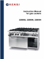
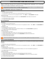
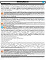
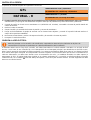
fig.1
Cod.
225882
225899
226094
Mod.
225882
225899
226094
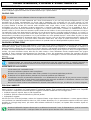
Dim. Esterne, External dimensions,
Außenmaße, Dim. Extérieures,
Dimensiones externas
mm
800
1200
1200
mm
700
700
700
mm
900
900
900
Potenza fuochi, Top burner power,
Nennleistung, Puissance installée,
Potencia instalada.
2×3.5kW
2×6kW
3×3.5kW
3×6kW
3×3.5kW
3×6kW
Forno elettrico ventilato, Electric
fan oven, Elektrischer Backofen,
Four électrique, Horno eléctrico.
3kW
-
Attacco gas, Gas inlet connection, Gasanschluss, Arrivée gaz, Entrada gas.
Morsetto equipotenziale, Unipotential earthing connection, Potentialausgleich, Vis équipotentiel, Tornillo
equipotencial.
490
150 190~
850~900
55050
800 - 1200
100
50 50
100

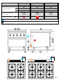
fig.3
fig.4
fig.5
fig.6
fig.7
fig.8

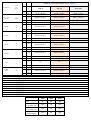
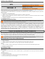
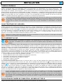
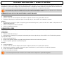
CAT./KAT./CAT.
P [mbar]
G20
G30-31
COOKPRO: BRUCIATORE / BRENNER / BURNER / BRÛLEUR / QUEMADOR
kW
3,5 kW [R] 6 kW [UR] 4,0 kW [OVEN]
Dim.
1/100 mm 1/100 mm 1/100 mm
II 2H3 + II 2E+ 3+
II 2H 3B/P
20
28..30/37
MAX
1,40 G20 / 0,92 G30-31 1,85 G20 / 1,20 G30-31 1,60 G20 / 1,02 G30-31
MIN
REG G20 / 0,40 G30-31 REG G20 / 0,55 G30-31 REG G20 / 0,55 G30-31
H [mm]
0,00 G20 / 3,00 G30-31 1,00 G20 / 2,00 G30-31 -
II 2E3 B/P
20
50
MAX
1,40 G20 / 0,80 G30-31 1,85 G20 / 1,05 G30-31 -
MIN
REG G20 / 0,40 G30-31 REG G20 / 0,55 G30-31 -
H [mm]
0,00 G20 / 3,00 G30-31 1,00 G20 / 2,00 G30-31 -
II 2H3 B/P
20
50
MAX
1,40 G20 / 0,80 G30-31 1,85 G20 / 1,05 G30-31 -
MIN
REG G20 / 0,40 G30-31 REG G20 / 0,55 G30-31 -
H [mm]
0,00 G20 / 3,00 G30-31 1,00 G20 / 2,00 G30-31 -
II 2E3 B/P
20
37
MAX
1,40 G20 / 0,92 G30-31 1,85 G20 / 1,20 G30-31 -
MIN
REG G20 / 0,40 G30-31 REG G20 / 0,55 G30-31 -
H [mm]
0,00 G20 / 3,00 G30-31 1,00 G20 / 2,00 G30-31 -
II 2HS3 B/P
25
30
MAX
1,30 G20 / 0,92 G30-31 1,70 G20 / 1,20 G30-31 -
MIN
REG G20 / 0,40 G30-31 REG G20 / 0,55 G30-31 -
H [mm]
0,00 G20 / 3,00 G30-31 1,00 G20 / 2,00 G30-31 -
I3B/P
/
30
MAX
0,92 1,20 -
MIN
0,40 0,55 -
H [mm]
3,00 2,00 -
MAX
1,40 (D) G25 / 0,92 G30-31 1,80 (D) G20 / 1,20 G30-31 -
II2EK3B/P
II2L3B/P
25
30
MIN
REG G20 / 0,40 G30-31 REG G20 / 0,55 G30-31 -
H (mm)
0,00 G20 / 3,00 G30-31 1,00 G20 / 2,00 G30-31 -
CAT./KAT./CAT. P [mbar]
Paese / Land / Country / Pays / País
II2H3+ 20 28..30/37 IT,ES,GB,GR,IE,PT,CZ,SK,AE,MA,TN,DZ,RL
II2E+3+ 20/25 28/37 FR,BE
II2H3B/P 20-30 DK,SE,FI,SI,EE,LT,LV,NO,IS,HR,PR,RO,BG,MD,YU,BY,MC,RU,UA,RS,TR
II2E3B/P 20-50 DE
II2H3B/P 20-50 AT,CH,LU
II2E3B/P 20-37 PL
II2HS3B/P 25-30 HU
I3B/P 30 CY,MT
II2EK3B/P II2L3B/P 25-30 NL
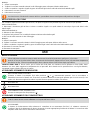
225882 225899 226094
Qn [kW] 19 28,5 28,5
Metano (G20)
(Hi = 9.45 kWh/m
3
) m
3
/h
2,01 3,01 3,01
Metano (G25)
(Hi = 8.125 kWh/m
3
) m
3
/h
2,34 3,51 3,51
GPL (G30)
(Hi = 12.68 kWh/kg)kg/h
1,50 2,25 2,25

NL
De toestel categorie “I2EK” wordt vermeld is bedoeld:
Dit toestel is afgesteld voor de toestelcategorie K (I2K) en is geschikt voor
het gebruik van G en G+ distributiegassen volgens de specificities zoals
die zijn weergegeven in de NTA 8837:2012 Annex D met een Wobbe-
index van 43,46 – 45,3 MJ/m3 (droog, 0°C, bovenwaarde) of 41,23 –
42,98 (droog, 15°C, bovenwaarde).
Dit toestel kan daarnaast worden omgebouwd en/of opnieuw worden
afgeregeld voor de toestelcategorie E (I2E).
Dit houdt derhalve in dat het toestel: “geschikt is voor G+-gas en H-gas,
ddan wel aantoonbaar geschikt is voor G+-gas en aantoonbaar geschikt is
te maken voor H-gas” in de zin van het “Besluit van 10 mei 2016 tot
wijziging van het Besluit gastostellen…”.
GB
To the appliance category “I2EK” this is understood as:
This appliance was configured for the appliance category K (I2K) and is
suitable for the use of G and G+ distribution gases according to the
specifications as included in the NTA 8837:2012 Annex D with a Wobbe
index of 43.46 – 45.3 MJ/m3 (dry, 0°C, upper value) or 41.23 – 42.98 (dry,
15°C, upper value).
This appliance can moreover be converted and/or again be calibrated for
the appliance category E (I2E).
This therefore implies that the appliance: “is suitable for G+ gas and H gas
or is demonstrably suitable for G+ gas and can demonstrably be made
suitable for H gas” within the meaning of the “Dutch Decree of 10 May
2016 regarding amendment of the Dutch Gas Appliances Decree…”.

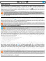
INSTALLATION
GENERAL INSTRUCTION
The appliance described in this manual has been built to meet 2014/35/EU (Safety), 2014/30/EU (EMC), Re 2016/426/EU
(GAR), Re 1935/2004/EC, Re 2023/2006/EC directives; and UNI EN 203…, UNI EN 437, EN 60335-1, EN60335-2-36 and
EN55014 standards. This appliance has been designed exclusively for cooking food, any other use is considered improper: be
careful that no live animal, person or “dangerous” objects are placed inside the oven. It should only be used by qualified
personnel in professional kitchens. Materials in contact with foodstuffs are suitable for use. The unit must never be left
unattended when it is being used! The appliance should be checked once a year by a qualified technician. Switch the appliance
off in the case of a failure or malfunction.
The appliance should be installed under an extractor hood for removing any cooking fumes.
Care must be taken when using the appliance because the cooking surfaces are very hot. The appliance must be
installed, connected and serviced properly by qualified personnel according to the regulations and directives in force in
the country where it is installed, as well as the instructions in this manual.
UNIT CHARACTERISTICS
These installation and user's instructions refer to the category II2H3+ gas ranges. The data plate is outside the back panel to
the appliance. The supplementary plate is also made of self-adhesive polyester and is affixed near the data plate; it contains all
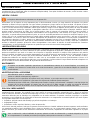
information regarding the appliance. The gas distribution network fitting fig.1 meets ISO 7/1 and ISO 228/1 standards with a ø
½” connection, situated at the back of the machine. The structure of the appliance is made of stainless steel, the burners are
made of cast iron and the oven is made of stainless steel. All models have adjustable feet. The main gas pipe is made of
galvanized steel. The pipes between the tap and burner are made of copper.
Install a shut-off cock in the line between the appliance and the gas distribution network. Install an omnipolar switch
between the appliance and the electrical distribution network.
CONNECTION TO THE GAS DISTRIBUTION NETWORK
Before you install the appliance, make sure that the gas company has authorised the installation, compare the
data relevant of the appliance (data plate) with the local supply.
Remove the packaging from the appliance as well as the protective plastic sheet, and, if necessary, remove traces of glue with
a suitable solvent. To dispose of the packaging, follow local directives (for more details refer to the chapter “ECOLOGY AND
THE ENVIRONMENT”. Prior to connecting the unit to the gas network, check the data plate to see if the unit has been set and
tested for the type of gas supplied. If the gas type indicated on the data plate is not the same as that supplied, please refer to
the paragraph “CONVERSION AND ADAPTATION”. Connect the appliance to the gas distribution network using metal pipes
with a suitable diameter; install a homologated shut-off cock between the appliance and the distribution network. If flexible pipes
are used, they must be made of stainless steel according to the standards in force. When installing the appliance, all the
regulations in force must be observed, such as:
Installation and safety standards in force.
Regional and/or local regulations, such as building codes.
Directives and regulations of the electricity board.
Accident prevention regulations in force.
Fire prevention regulations.
Applicable I.E.C. regulations.
We recommend installing the appliance in a well-ventilated environment, or under an extraction hood to remove the fumes or
vapors produced during the cooking cycle. All models have an equipotential earth terminal fig.1 in the bottom. The appliances
with an electric oven have a hole for the cable fig.1. The appliance can be installed alone or in line. Respect a minimum
distance of 80mm between the appliance and any walls made of flammable material, partitions, kitchen furniture or nearby
equipment. The contact surfaces must be covered with non-combustible heat insulating material. The appliance, and especially
the power lead, must not be installed anywhere near heat sources and the temperature of the place in which the appliance is
installed must not rise above 50°C. After installing the appliance check for any leaks in the fittings. Use non-corrosive foam
products, such as leak detection sprays, to look for any leaks.
When checking for leaks do not use naked flames!
The manufacturer shall not be held responsible and the guarantee is void in the case of damage caused by negligence
in following the operating and installation instructions or by improper use. The guarantee is void in the case of
connections which have been made in a way which doesn't meet the current standards and fire-fighting regulations.
EVACUATION OF BURNT GASES: A1 APPLIANCE
Appliances must be installed under an extraction hood with forced draught, subjected to gas supply.

CHECKING THE PRESSURE
The distribution network pressure must meet the following specifications.
LPG
ALLOWED from 20/25 to 35/45 mbar
NOT ALLOWED below 20/25 above 35/40 mbar
METHANE - H
ALLOWED from 17 to 25 mbar
NOT ALLOWED below 17 above 25 mbar
If the gas distribution network pressure on the installation site doesn't meet the above values, inform the gas board and do not
turn the unit on until the cause and a solution have been found. The distribution network pressure can be taken with a U
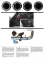
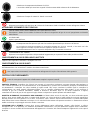
manometer (min. definition 0.1 mbar), connected to the pressure outlet behind control panel fig.8.
1. Remove the control panel.
2. Remove the screw and sealing washer from the pressure outlet and connect the manometer.
3. Turn the unit on following the enclosed instructions and check that the pressure is within the permitted pressure range.
4. Disconnect the manometer and replace the screw and the sealing washer in the pressure outlet.
5. Replace the control panel.
ELECTRICAL CONNECTION
Before proceeding with the electrical connection, check the specifications on the data plate.
The appliance is supplied with a power cable (3x1,5 H07RN-F).
The installer must make the connection after having installed a standard plug connected to an easy-to-reach socket, or in case
of a permanent connection, after having installed a main switch, which, as well as being easy to reach, must disconnect all of
the contacts supplying electrical energy to the appliance, with a minimum distance of at least 3mm between the poles. The earth
wire must never be disconnected.
The power cable must not be installed near heat sources and the temperature of the place in which the appliance is installed
must not rise above 50°C. The appliance must also be connected to an equipotential earth. This connection can be made using
the equipotential terminal marked with the symbol , placed under the appliance near the right rear foot. The equipotential wire
must have a section of 10mm
2
.

TRANSFORMATION AND ADAPTATION
To convert the appliance to another type of gas, e.g. from natural gas to LPG, the nozzles of the main burner, by-pass and pilot
light have to be changed. All the nozzles are marked with a number that indicates the diameter in 1/100 of a mm and are
supplied in a bag. After each conversion or adaptation, the unit must undergo an operating test and the supplementary plate
must be updated according to the conversion or adaptation carried out.
Connection to the distribution network, installation, and maintenance of the appliance must only be carried out by
qualified technicians only, in observance of all applicable regulations!
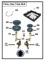
COOKTOP BURNER, NOZZLES AND AIR ADJUSTMENT
BURNER:
1. Pull the knobs off.
2. Remove the control panel by unscrewing the fixing screws at the rear.
3. Replace nozzle with a suitable one for the new type of gas indicated in the "MAX" nozzles table.
MINIMUM:
4. Unscrew and replace or adjust the minimum by-pass nozzle fig.8 on the basis of the indications in the nozzles table.
5. Remove the control panel.
6. Replace the knob.
OVEN BURNER
To replace the nozzle of the oven burner, the pilot light and adjust the primary air, follow the instructions below:
BURNER:
1. Remove the base of the oven fig.7.
2. Unscrew and replace the nozzle with a suitable one for the new type of gas indicated in the "MAX" nozzles table.
ADJUSTING THE AIR:
3. Loosen fixing screw
4. Adjust the primary air mount the bush a distance indicated in nozzles table.
5. Block the bush, by screwing in fixing screw.
MINIMUM:
6.Adjust the minimum by-pass nozzle fig.16 on the basis of the indications in the nozzles table.
7. Replace the knob.
If the bottom of the oven chamber is removed, it must be put back in exactly the same position.
GRILL OVEN BURNER
To replace the nozzle of the grill oven burner, the pilot light and adjust the primary air, follow the instructions below:
BURNER:
1. Remove the grill oven burner.
2. Unscrew and replace the nozzle with a suitable one for the new type of gas indicated in the "MAX" nozzles table.
3. Block the bush, by screwing in fixing screw.
MINIMUM:
4. Unscrew and replace or adjust the minimum by-pass nozzle fig.16 on the basis of the indications in the nozzles table.
5. Replace the knob.

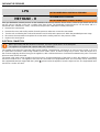
USE
PUTTING THE RANGE INTO SERVICE
The first time the oven is switched on you will notice a bad smell due to production residues such as grease, oil and
resin.
When using the oven for the first time you should switch it on at the highest temperature for at least 1 hour, making
sure that it is empty. After this time has elapsed, the oven is ready for use.
Clean the oven after every time you use it.
RECOMMENDATIONS FOR USE: For best results, it is a good rule never to put food in a cold oven. It is best to wait for the
oven to reach the chosen temperature first. Never line the oven walls with aluminum sheets, especially the bottom part of the
cooking chamber.
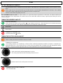
TURNING THE BURNERS ON AND OFF
COOKTOP BURNERS:
Press and turn the knob fig.3 from position “ ” to " " keeping it pressed in. After the flame has lit, hold the knob down
for roughly 10 seconds; so the thermocouple heats up and keeps the safety valve open.
Burner min
Burner MAX
TURNING THE BURNER OFF:
Turn the knob to the “ ” position.
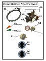
TURNING THE ELECTRIC OVEN ON AND OFF
All the cooking must be done with the oven door closed.
TURNING THE OVEN ON:
I The heating elements are controlled by a selector switch, while the temperature inside the chamber is controlled by a
thermostat (50-270°C). The selector lets you choose the most suitable type of heating using the appropriate heating
elements. The green indicator light will come on to indicate that the oven is connected to the mains.
Set the knob to the desired temperature 50-270°C.
The orange light indicate that the heating elements are on.
Select manual or the cooking time 10-120 min.
TURNING THE ELECTRIC OVEN OFF:
Turn the knobs to 0.

TURNING THE GAS OVEN ON AND OFF
All the cooking must be done with the oven door closed.
The burner has a safety valve that cuts off the gas supply if the flame should accidentally go out.
TURNING THE OVEN ON:
Open the oven door.
Set the knob to the desired temperature 125-250°C.
At the same time press piezoelectric igniter several times, to light the pilot flame.
After the flame has lit, hold the knob down for roughly 10 seconds; so the thermocouple heats up and
keeps the safety valve open.
Through the hole in inspection cover fig.7 check that the flame is alight.
TURNING THE GAS OVEN OFF:
Turn the knob to position “0” pressing it slightly so it goes past the stop at the minimum position.
WHAT TO DO IF THE UNIT IS NOT GOING TO BE USED FOR A LONG TIME
Turn the gas shut-off cock installed upstream of the appliance off. Clean the unit thoroughly following the instructions and dry it
carefully.
MALFUNCTIONS
In any case, if you suspect the presence of anomalies, ALWAYS CLOSE the gas shut-off cock and inform the authorized after-
sales service.
Unauthorized persons should never attempt to repair the appliance, or carry out maintenance. Tampering with the
appliance voids the warranty!
OPERATIONAL CHECKS
Before the unit is delivered to the user the following checks must be carried out:
THERMAL CAPACITY: Check that the pressure and type of gas supplied where the unit is to be used is the same as that
indicated on the plate. If it is not, the unit must either be converted or adapted. In this case please refer to the paragraph:
“Conversion or Adaptation”. Check that the right nozzles have been installed. Refer to the nozzle table and check that the
nozzles indicated in the table are the same as those installed on the unit. An additional check of thermal capacity entails
verifying the gas consumed with the volumetric method: light the burner and after approximately 10 minutes (operating
conditions) check that the gas flow (in m
3
/h or in kg/h) corresponds to that indicated in nozzle table.
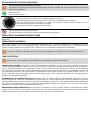
APPEARANCE OF THE FLAME AND PRIMARY AIRFLOW: The flame should be blue and there should be no yellow dots in it;
it must be stable at its base. If the colour of the flame tends towards yellow, it means the primary airflow is not adjusted properly.
If the primary airflow is too fast the flame will be short and tend to burn above the burner. The appearance of the flame must
also be checked 15 minutes after the appliance has been running at full power. The flame must remain stable even when
passing quickly from minimum to maximum.
USER'S INSTRUCTIONS: The user must be trained on the correct use and functions of the appliance. We would like to point
out that any alterations made to the room where the unit is installed could influence the amount of air used for combustion and
for this reason the function of the unit must be checked again. When these checks have been done, test the unit for leaks.

MAINTENANCE & CLEANING
REPLACING PARTS
Only qualified personnel should replace faulty parts. Prior to commencing any kind of work, disconnect the unit from the gas
distribution network and the electrical power supply.
CLEANING AND CARE OF THE APPLIANCE
The unit must be cold to clean it.
Keeping the appliance clean is very important for a long and trouble-free working life. The removable parts should be washed
separately with warm water and detergent, then rinsed in running water. The steel parts may be cleaned with a damp cloth and
with a non-abrasive detergent and then dried by using a soft, dry cloth. For very resistant stains, use hot water and vinegar. Do
not use harsh or abrasive detergents to clean the stainless steel parts. Iron cleaning pads should not be used as they cause the
formation of rust. For the same reason, avoid contact with ferrous materials. When cleaning, avoid using abrasive paper or
cloth; instead and only in special cases you can use pumice stone powder; we recommend using sponges (ex. Scotch) to
remove stubborn deposits. You can also use common sprays for cleaning ovens and grills to remove stubborn deposits. If spray
products are used, follow the manufacturer’s instructions. The enamelled parts should not be cleaned with abrasive or acid
products. Avoid using steel wool or metal pads for cleaning. It is important to clean the oven each time you use it; this way it will
be easier to remove cooking residues and avoid burning them the next time the oven is used, which would also result in a bad
smell. To minimise the emission of polluting substances in the environment we suggest cleaning the appliance with products
that are at least 90% biodegradable.
CLEANING INSIDE THE OVEN
Turn the electric power off or make sure you have turned the burner of the oven of before doing any work on it. Let the oven
cool down and clean it thoroughly with a damp cloth and warm water using a non-abrasive detergent (or with the special
products readily available for cleaning ovens). Do not use abrasive cloths or pads or other products that could irreparably
damage the enamel. Normal cooking temperatures help transform grease and oil splashes into a mist of residual dust that can
be easily removed at the end of the cooking process when the oven has cooled down by simply using a damp sponge. We
recommend heating the oven periodically to the maximum temperature so that the residual dust can be removed once it has
cooled down. Be careful not to damage the thermostat sensor inside the oven while you are cleaning it.
MAINTENANCE
The appliance needs no specific maintenance besides normal cleaning; we do however suggest having it checked
once a year by the assistance centre for which, we recommend drawing up a maintenance contract.
Safety precautions
REMEMBER THAT THE APPLIANCE:
Must never be left unattended when it is being used!
When the unit is switched on, its surfaces get very hot so please take great care!
The appliance is intended for professional use and therefore only qualified personnel should use it!
Installation as well as any conversion or adaptation to a different type of gas must be carried out in accordance with
current laws and only by qualified and authorized personnel.
In the case of fire, close the shut-off cock to cut off the gas supply immediately, then use a suitable fire extinguisher to
fight the fire
ECOLOGY AND ENVIRONMENT
Our appliances are studied and optimised, with lab tests, to provide high performance and yields. However, to keep energy
consumption low (electricity, gas and water), we suggest not using the appliance for any length of time if it is empty or in
conditions that compromise optimum yield. All packaging materials are environment-friendly. They can be kept without problem
or burnt in a waste incinerator plant. The plastic components that can be recycled are:
Polyethylene: external packaging material and/or pluribol film
Polypropylene: straps
Polystyrene foam: corner pieces, sheets and protection blocks.
At the end of the appliance’s useful life, dispose of it properly. 90% of each appliance is made of metal (stainless steel, iron,
aluminated sheet, etc.) hence it can be recycled by the relative recycling organisations in compliance with the standards in force
in your country.
Prepare the appliance for disposal, so it cannot be used any more, by removing the power cable and any locks so that
no one can get locked inside accidentally.

INSTALLATION
ALLGEMEINE ANMERKUNGEN
Das in diesem Handbuch beschriebene Gerät wurde unter Beachtung der Anforderungen der Richtlinie 2014/35/EU (Safety),
2014/30/EU (EMC), Re 2016/426/EU (GAR), Re 1935/2004/EC, Re 2023/2006/EC, und der Normen UNI EN 203…, UNI EN
437, EN 60335-1, EN60335-2-36 und EN55014 gebaut. Dieses Gerät ist ausschließlich für das Kochen und Garen von Speisen
vorgesehen. Jeder andere Gebrauch gilt als ungeeignet: bitte beachten Sie, dass keine lebenden Tiere, Personen oder
"gefährliche" Gegenstände in den Ofen liegen oder gelegt sind! Es ist für den Einsatz in Großküchen bestimmt und darf nur von
qualifiziertem Personal betrieben werden. Materialien in Kontakt mit Lebensmitteln sind geeignet für . Das Gerät nur unter
Aufsicht betreiben! Außerdem ist es empfehlenswert, einmal jährlich eine Kontrolle von qualifiziertem Personal durchführen zu
lassen. Im Schadensfall oder bei mangelhaftem Betrieb das Gerät ausschalten.
Es ist empfehlenswert, das Gerät unter einer Abzugshaube aufzustellen, um die während des Garens erzeugten
Dämpfe abzuleiten. Es ist besonders darauf zu achten, dass sich die Geräteoberflächen während des Betriebs stark
erhitzen. Der Anschluss, die Installation und die Wartung müssen von Fachpersonal gemäß den Vorschriften und
Gesetzen des Landes sowie in Übereinstimmung mit dieser Gebrauchsanweisung durchgeführt werden.
ANGABEN ZUM GERÄT
Die vorliegende Installations- und Wartungsanleitung gilt für Gasherde der Kategorie II2H3B/P (AU) II2E3B/P (DE). Das
Typenschild aus selbsthaftendem Polyester befindet sich hinter der Bedienblende (im Geräteinneren). Das Zusatzschild,
ebenfalls aus selbstklebender Polyesterfolie, ist neben dem Typenschild angebracht und es enthält alle Informationen über die
Einstellung des Gerätes. Der Anschluss für die Verbindung mit der Gasleitung (Abb.1) entspricht den Vorschriften ISO 7/1
mit ø ½” und befindet sich an der Geräteunterseite. Die Gerätestruktur ist aus Edelstahl, die Brenner aus Gusseisen und die
des Backofens aus Edelstahl gebaut. Alle Modelle sind mit höhenverstellbaren Stellfüßen ausgestattet. Die Gas-Hauptleitung
besteht aus verzinktem Stahl, die Anschlussleitungen vom Hahn zum Brenner aus Kupfer.
Zwischen dem Gerät und der Gasversorgungsleitung einen Absperrhahn einbauen. Zwischen dem Gerät und der
Stromversorgungsleitung einen Schutzschalter einbauen.
ANSCHLUSS AN DIE GASLEITUNG
Vor der Geräteinstallation unbedingt beim Gasversorgungsunternehmen eine Installationsgenehmigung einholen und
die Daten der Geräteeinstellung (Typenschild) mit der örtlichen Gasversorgung konfrontieren.
Die Geräteverpackung entfernen, die Schutzfolie abnehmen und eventuelle Klebstoffrückstände mit einem geeigneten
Lösungsmittel entfernen. Das Verpackungsmaterial muss vorschriftsmäßig entsorgt werden (nähere Details dazu im Kapitel
„UMWELTSCHUTZ“). Bevor das Gerät angeschlossen wird, ist auf dem Geräteschild festzustellen, ob das Gerät für die
vorhandene Gas Art eingerichtet und zugelassen ist. Falls die auf dem Geräteschild angegebene Gas Art mit der vorhandenen
Gas Art nicht übereinstimmt, verweisen wir auf Abschnitt ”UMSTELLUNG UND ANPASSUNG”. Der Anschluss an das
Gaszuleitungsnetz muss mit Metallrohren mit entsprechendem Durchmesser und unter Zwischenschaltung eines anerkannten
Absperrhahns durchgeführt werden. Sollten Schlauchleitungen zur Anwendung kommen, müssen diese gemäß müssen diese
gemäß DIN 3383 Teil 1 oder DIN 3384 (für Deutschland) und den gültigen Normen aus rostfreiem Stahl (für die Schweiz und für
Österreich) bestehen.
Während der Installation sind alle geltenden Vorschriften zu berücksichtigen:
Regionale bzw. lokale Sicherheit- und Bauvorschriften
Geltende Unfallverhütungsgesetze
Brandschutzvorschriften
Entsprechende IEC-Vorschriften
Für Deutschland
DVGW-Arbeitsblatt G600 (TRGI) „Technische Regeln für Gasinstallation“.
TRF „Technische Regeln für Flüssiggas“.
Richtlinien und Bestimmungen des Gasversorgungsunternehmens (EUV).
DVGW-Arbeitsblatt G634 „Installation von Großküchen-Gasverbrauchseinrichtungen“.
Einschlägige Rechtsverordnungen.
Für Schweiz
SVGW-Gasleitsätze G1 (2002)
EKAS-Richtlinie Nr. 1942: Flüssiggas, Teil 2 (EKAS: Eidgenössische Koordinationskommission für Arbeitssicherheit)
Vorschriften der Vereinigung Kantonaler Feuerversicherungen (VKF)
Richtlinien der SUVA.
Das Gerät zur Ableitung der beim Kochen entstehenden Dämpfe vorzugsweise in einem gut gelüfteten Raum oder unter einer
Dunstabzugshaube aufstellen.

Alle Modelle sind an der Rückseite mit einem Potentialausgleich (Abb.1) ausgestattet. Die Geräte mit Elektrobackofen sind
mit einem Netzkabeleingang (Abb.1) ausgestattet. Das Gerät kann sowohl freistehend als auch gemeinsam mit anderen
Geräten installiert werden. Zwischen dem Gerät und eventuellen Wänden aus brennbarem Material, Trennwänden,
Küchenmöbeln oder nebenstehenden Geräten mindestens 80mm Abstand halten Die Kontaktflächen müssen mit nicht
brennbarem Wärmeisoliermaterial verkleidet werden.
Das Gerät darf nicht in der Nähe von Wärmequellen aufgestellt werden, das gilt in besonderem Maße für das
Versorgungskabel. Die Raumtemperatur muss stets unter 50°C liegen. Nach der Installation die Anschlüsse auf ihre Dichtheit
prüfen. Zur Suche nach Leck Stellen einen nicht korrosiven Schaum, wie z.B. Lecksuch-sprays verwenden.
Bei der Dichtheitsprüfung auf keinen Fall offene Flammen benutzen!
Der Hersteller übernimmt keine Garantieverpflichtung für Beschädigungen, die aufgrund einer Nichtbeachtung der
Installations- und Bedienungsanleitung oder durch fahrlässige Bedienung entstehen. Außerdem übernimmt er keine
Garantieverpflichtungen für einen nicht mit den gültigen Normen und Brandschutzvorschriften konformen Anschluss.
ABGASFÜHRUNG: A1 TYP
Die Geräte müssen unter einer Dunstabzugshaube mit Zwangslüftung installiert werden, die der Gasversorgung unterlegen ist.
DRUCKKONTROLLE
Der Leitungsdruck muss folgenden Daten entsprechen.
FLÜSSIGGAS
ZULÄSSIG zwischen 20/25 und 35/45 mbar
NICHT ZULÄSSIG unter 20/25 bzw. über 35/40 mbar
ERDGAS - H
ZULÄSSIG zwischen 17 und 25 mbar
NICHT ZULÄSSIG unter 17 bzw. über 25 mbar
Sollte der Leitungsdruck am Aufstellungsort nicht den oben genannten Werte entsprechen, das GVU benachrichtigen und keine
Inbetriebnahme vornehmen, bevor die Ursache nicht geklärt und behoben ist.
1. Der Druck ist mit einem U-Rohr Manometer (Auflösung mind. 0.1 mbar) messbar. Das Manometer kann am Druckanschluss
Abb.8 hinter der Blende angeschlossen werden.
2. Die Bedienblende abnehmen.
3. Die Schraube und Dichtungsscheibe vom Druckanschluss nehmen und das Manometer anschließen.
4. Das Gerät gemäß der Bedienungsanleitung in Betrieb nehmen und prüfen, ob der angegebene Druck im zulässigen Bereich
liegt.
5. Das Manometer wieder abnehmen und die Schraube mit dem Dichtring wieder am Druckanschluss anordnen.
6. Die Bedienblende wieder montieren.
ANSCHLUSS AN DIE STROMLEITUNG
Vor dem Anschluss an die Stromleitung die Daten des Typenschilds prüfen.
Das Gerät wird mit Netzkabel geliefert (3x1,5 H07RN-F).
Der Installateur hat für den Anschluss unter Zwischenschaltung eines normalisierten Steckers zu sorgen, mit einer Steckdose
verbindet, die leicht zugänglich sein muss. Im Falle von einer festen Verbindung, muss der Installateur einen Schutzschalter
anschließen, der nicht nur leicht zugänglich sein muss, aber auch den Strom allpolig unterbrechen muss. Seine
Kontaktöffnungsweite muss pro Pol mindestens 3mm betragen. Das Gerät muss unbedingt geerdet werden. Das Netzkabel darf
nicht in der Nähe von Hitzewellen liegen und die Umgebung muss nie eine Temperatur höher als 50 ° C haben. Das Gerät ist
ferner in ein Potentialausgleichssystem einzubeziehen. Der Anschluss ist mit der durch gekennzeichneten Schraube
durchzuführen, die sich unter dem Gerät in der Nähe des rechten hinteren Füßchens befindet. Das diesbezügliche Kabel muss
einen Querschnitt von 10mm
2
haben.

UMSTELLUNG UND ANPASSUNG
Die Umstellung auf eine andere Gas Art z.B. von Erdgas auf Flüssiggas erfolgt durch den Austausch der Hauptbrenner-,
Bypass- und Zündbrennerdüsen. Alle Düsen sind mit einer Ziffer (Durchmesser in 1/100) gekennzeichnet und in einem Beutel
mitgeliefert. Nach jeder Umstellung oder Anpassung ist eine Funktionskontrolle vorzunehmen und das Zusatzschild
entsprechend der erfolgten Umstellung bzw. Anpassung zu ändern.
Alle Maßnahmen bezüglich Anschluss, Installation sowie Wartung des Gerätes dürfen nur von qualifiziertem Personal
unter Beachtung aller entsprechenden Vorschriften durchgeführt werden!
KOCHPLATTENBRENNER, DÜSEN UND LUFTEINSTELLUNG
BRENNER:
1. Die Drehschalter herausziehen.
2. Die Bedienblende mittels Ausschrauben der unteren Befestigungsschrauben abnehmen.
3. Die Düse durch die für die neue Gas Art geeignete ersetzen - siehe „MAX“ in der Düsentabelle im Abschnitt.
KLEINSTSTELLUNG:
4. Die Bypass-Kleinststelldüse fig.8 ausschrauben und laut Düsentabelle im Abschnitt und austauschen.
5. Die Bedienblende wieder montieren.
6. Den Drehschalter wieder montieren.
BACKOFENBRENNER
Zum Austausch des Backofenbrenners, des Zündbrenners und zur Einstellung der Primärluft folgende Anweisungen beachten:
BRRENNER:
1. Den Backofensockel Abb.8 abnehmen.
2. Die Düse ausschrauben und durch die für die neue Gas Art geeignete ersetzen - siehe „MAX“ in der Düsentabelle im
Abschnitt.
LUFTEINSTELLUNG:
1. Die Befestigungsschraube Abb.7 lockern.
2. Die Primärluft des Luftregler-bügels auf den Abstand einstellen, der in der T1-Düsentabelle angegeben ist.
3. Den Bügel wieder mit der Schraube fixieren.
KLEINSTSTELLUNG:
1. Die Drehschalter herausziehen.
2. Die Bedienblende mittels Ausschrauben der unteren Befestigungsschrauben abnehmen.
3. Die Bypass-Kleinststelldüse ausschrauben und laut Düsentabelle im Abschnitt und austauschen.
4. Die Bedienblende wieder montieren.
5. Den Drehschalter wieder montieren
Sollte der Backofenboden entfernt werden, ist er nach der Einstellung wieder wie ursprünglich anzuordnen
GRILL GAS BACKOFENBRENNERS
Zum Austausch des grill gas Backofenbrenners, des Zündbrenners und zur Einstellung der Primärluft folgende Anweisungen
beachten:
BRENNER:
1. Entferner der grill gas Backofenbrenners.
2. Die Düse ausschrauben und durch die für die neue Gas Art geeignete ersetzen - siehe „MAX“ in der Düsentabelle im
Abschnitt.
LUFTEINSTELLUNG:
3. Die Befestigungsschraube lockern.
4. Die Primärluft des Luftregler-bügels auf den Abstand einstellen, der in der T1-Düsentabelle angegeben ist.
5. Den Bügel wieder mit der Schraube fixieren.
KLEINSTSTELLUNG:
6. Die Drehschalter herausziehen.
7. Die Bedienblende mittels Ausschrauben der unteren Befestigungsschrauben abnehmen.
8. Die Bypass-Kleinststelldüse ausschrauben und laut Düsentabelle im Abschnitt und austauschen (Abb.8).
9. Die Bedienblende wieder montieren.
10. Den Drehschalter wieder montieren.

GEBRAUCH
INBETRIEBNAHME
Bei der ersten Inbetriebnahme erzeugt der Backofen einen unangenehmen Geruch, der auf Produktionsrückstände,
wie Fette, Öle und Harz zurückzuführen ist.
Dadurch ist der Backofen zuerst mindestens 1 Stunde lang bei Höchsttemperatur leer zu betreiben. Danach ist der
betriebsbereit.
Den Backofen nach jedem Gebrauch reinigen.
GEBRAUCHSEMPFEHLUNGEN: Für ein gutes Gelingen Ihrer Speisen ist es empfehlenswert, diese nie in den kalten Backofen
einzuschieben. Die Speisen erst dann einschieben, wenn der Backofen die von Ihnen gewählte Temperatur erreicht hat. Die
Backofenwände und insbesondere die Backofensohle dürfen nicht mit Alufolie überzogen werden.
EIN-UND AUSSCHALTEN DER BRENNER
KOCHPLATTENBRENNER:
Den Drehschalter (Abb.3) drücken und von “ ” auf " " drehen. Mit einem Gaszünder oder einem Streichholz die
Zündflamme anzünden. Nach der Zündung den Drehschalter ca. weitere 10 Sekunden drücken; dadurch erhitzt sich
das Thermoelement und hält das Sicherheitsventil offen.
Brenner min
Brenner MAX
AUSSERBETRIEBNAHME DES GERÄTES:
Den Drehschalter auf Position “ ” drehen.
EIN- UND AUSSCHALTEN DES ELEKTRO-BACKOFENS
Beim Backen immer die Backofentür schließen.
EINSCHALTEN:
Den Thermostat-Drehschalter auf die gewünschte Temperatur einstellen (50-270°C). Über den Wählschalter wird die
gewünschte Heizung gewählt, d.h. die erforderlichen Heizelemente eingeschaltet. Aufleuchten der grünen
Kontrollleuchte bedeutet, dass das Gerät unter Spannung steht..
Den Thermostat-Drehschalter auf die gewünschte Temperatur einstellen 50-270°C.
Das Aufleuchten der orangen Kontrollleuchte bedeutet, dass die Heizelemente funktionieren.
Wählen Sie die manuelle oder die Garzeit 10-120 Minuten.
AUSSCHALTEN DES ELEKTRO-BACKOFENS:
Die Drehschalter auf “0” stellen. Den bauseitig installierten Stromschalter ausschalten.

EIN- UND AUSSCHALTEN DES GAS-BACKOFENS
Beim Backen immer die Backofentür schließen.
Der Brenner ist mit einem Sicherheitsventil ausgestattet, das die Gaszufuhr bei einem versehentlichen Ausschalten
der Flamme unterbricht.
EINSCHALTEN:
Die Backofentür öffnen.
Den Drehschalter auf die gewünschte Temperatur drehen 125-250°C.
Gleichzeitig mehrmals den Zündschalter Abb. 2 drücken, um die Zündflamme zu zünden.
Nach der Zündung den Drehschalter ca. weitere 10 Sekunden drücken; dadurch erhitzt sich das
Thermoelement und hält das Sicherheitsventil offen.
Die Flamme über das Inspektionsloch Abb.7 prüfen.
AUSSCHALTEN DES GAS-BACKOFENS:
Den Drehschalter leicht drücken und über die Kleinststellung auf “0” drehen.
VERHALTEN BEI LÄNGEREM BETRIEBSSTILLSTAND
Den Gasabsperrhahn und den Hauptschalter bauseitig schließen. Das Gerät laut Anleitungen reinigen und sorgfältig
abtrocknen.
VERHALTEN IM SCHADENSFALL
Nicht immer hängt ein Schaden von der Qualität der Bestandteile ab, die in unserem Fall erstklassig ist. Schäden können durch
Staub oder Schmutz, der in die Betriebsteile eintritt, verursacht werden. Sollte der Verdacht auf eine Betriebsstörung des
Gerätes vorliegen, IMMER den Gasabsperrhahn schließen und den autorisierten Kundendienst verständigen.
Auf keinen Fall dürfen unbefugte Personen versuchen, die Reparatur durchzuführen. Dadurch verfällt die Garantie.
FUNKTIONSPRÜFUNG
Das Gerät ist vor der Übergabe an den Benutzer auf nachfolgende Punkte zu kontrollieren:
THERMISCHE LEISTUNG: Überprüfen, ob die am Aufstellungsort vorhandene Gas Art und der Druck mit den Angaben des
Typenschilds übereinstimmen Sollte das nicht der Fall sein, ist eine Umstellung oder Anpassung vorzunehmen, dazu verweisen
wir auf Abschnitt ”Umstellung und Anpassung”. Prüfen, ob die richtigen Düsen installiert sind. Dazu in der Düsentabelle
nachsehen und sicherstellen, dass die am Gerät installierten Düsen den Angaben entsprechen. Zur zusätzlichen Kontrolle kann
eine volumetrische Messung des Gasdurchflusses vorgenommen werden. Dazu den Brenner in Betrieb nehmen, nach ca. 10
Minuten (Erreichen des Betriebsregimes) mit einem Gaszähler prüfen, ob der gemessene Durchfluss (in m
3
/h bzw. kg/h) den
Angaben der Düsentabelle entspricht.
FLAMMENBILD UND PRIMÄRLUFTSTROM: Die Flamme muss eine blaue Farbe, ohne gelbe Spitzen, aufweisen und an der
Basis stabil brennen. Wenn das Flammenbild gelb durchzogen ist, ist die Primärluft nicht richtig eingestellt. Bei zu großem
Primärluft-Volumenstrom ist die Flamme kurz und neigt zur Abhebung vom Brenner. Die Überprüfung des Flammenbilds muss
auch nach einer Betriebsdauer von 15 Minuten bei Höchstleistung erfolgen. Die Flamme muss auch nach einer jähen
Umstellung von der Klein- in die Großstellung stabil brennen.
ANWEISUNGEN FÜR DEN BENUTZER: Dem Benutzer die Funktionen und den korrekten Gebrauch und Einsatz des Gerätes
erklären. Darauf hinweisen, dass bauliche Änderungen, die die Verbrennungsluftzufuhr beeinflussen können, einer erneuten
Funktionskontrolle des Gerätes bedürfen. Zum Abschluss das Gerät auf Gasdichtheit prüfen.
.

WARTUNG UND REINIGUNG
AUSTAUSCH VON TEILEN
Der Austausch von defekten Teilen hat nur durch Fachpersonal zu erfolgen. Bevor jegliche Arbeit angefangen wird, ist
grundsätzlich der Gasabsperrhahn zu schließen. Nach Abnahme der Bedienblende sind alle Funktionsteile des Gerätes leicht
zugänglich.
REINIGUNG UND INSTANDHALTUNG
Die Reinigung ist nur bei abgekühltem Gerät vorzunehmen.
Die Reinigung ist für einen einwandfreien Betrieb und eine lange Lebensdauer des Geräts sehr wichtig. Die abnehmbaren Teile
separat mit warmem Wasser und Reinigungsmittel waschen und unter fließendem Wasser nachspülen. Die Geräteteile aus
Stahl können mit einem feuchten Lappen und einem nicht scheuernden Mittel gereinigt und danach mit einem trockenen,
weichen Lappen trockengewischt werden. Für besonders hartnäckige Flecken ist warmes Wasser und Essig anzuwenden. Zur
Reinigung der Teile aus rostfreiem Stahl, keine aggressive Mittel oder scheuernde Reinigungsmittel verwenden. Die Benutzung
von Stahlwolle auf Edelstahlteilen ist zu vermeiden, da sich hierdurch Rost bilden könnte. Aus demselben Grund ist der Kontakt
mit eisenhaltigem Material, schweren oder rauen Lappen bzw. mit Stahlwolle zu meiden. Glaspapier oder Schmirgelpapier
sollten bei der Reinigung nicht verwendet werden; man kann in besonderen Fällen pulverförmigen Bimsstein verwenden; bei
stärkerer Verschmutzung empfehlen wir die Benutzung von Schwämmen (z.B. Schwamm der Fa. Scotch). Bei hartnäckigen
Verschmutzungen kann handelsüblicher Backofen- oder Grillreiniger zur Hilfe genommen werden. Dazu sind die Hinweise des
jeweiligen Herstellers zu beachten. Zur Reinigung der emaillierten Oberflächen sind weder Scheuermittel oder Säuren noch
Stahlwolle oder Metallscheuerlappen anzuwenden. Den Backofen unbedingt nach jedem Gebrauch reinigen. Dadurch können
Speiserückstände einfacher entfernt werden und sie erzeugen beim nächsten Gebrauch keinen schlechten Geruch. Um die
Umweltbelastung durch Reinigungsmittel zu verringern, ist es empfehlenswert, das Gerät nur mit Produkten, die zu mindestens
90% biologisch abbaubar sind, zu reinigen.
REINIGUNG DES BACKOFENINNEREN
Vor jedem Eingriff die Stromzufuhr unterbrechen oder sicherstellen, dass der Backofenbrenner komplett ausgeschaltet ist. Den
Backofen abkühlen lassen und gründlich mit einem in lauwarmem Wasser und nicht scheuerndem Mittel (oder dafür geeignete,
im Handel erhältliche Mittel) getränktem Lappen reinigen. Keine Scheuerlappen oder andere Produkte anwenden, die das Email
unwiderruflich beschädigen könnten. Bei normalen Gartemperaturen werden die Fett- und Ölspritzer in Staub verwandelt,
welcher bei Garen und abgekühltem Backofen mit einem feuchten Lappen entfernt werden kann. Es ist empfehlenswert, den
Backofen von Zeit zu Zeit auf Höchsttemperatur zu betreiben, um danach den Staub bei abgekühltem Backofen zu entfernen.
Während der Reinigung ist darauf zu achten, dass der im Backofen befindliche Thermostatfühler nicht beschädigt wird.
WARTUNG
Das Gerät benötigt neben der normalen, regelmäßigen Reinigung keine besonderen Wartungsarbeiten; es wird
dennoch eine jährliche Kontrolle durch eine Kundendienststelle empfohlen, weshalb der Abschluss eines
Wartungsvertrages ratsam ist.
SICHERHEITSHINWEISE
FOLGENDES BEACHTEN:
Das Gerät nur unter Aufsicht betreiben!
Während des Betriebs werden die Geräteoberflächen heiß - besonders Acht geben!
Das Gerät ist für gewerbliche Zwecke geplant und darf nur durch Fachpersonal bedient werden!
Die Geräteinstallation sowie eine eventuelle Umstellung oder Anpassung auf eine andere Gas Art, darf nur gemäß den
einschlägigen gesetzlichen Vorschriften und durch qualifiziertes Fachpersonal, durchgeführt werden. Das Gerät
mindestens einmal jährlich von Fachpersonal kontrollieren lasse. Im Brandfall sofort den Gasabsperrhahn schließen
und einen geeigneten Feuerlöscher verwenden
UMWELTSCHUTZ
Unsere Geräte werden durch zahlreiche Laboruntersuchungen geprüft und optimiert, um so besonders hohe Leistungen zu
erzielen. Dennoch wird zur Einschränkung des Energieverbrauchs (Strom, Gas und Wasser) empfohlen, das Gerät nicht für
längere Zeit unbenutzt eingeschaltet zu lassen und es nur unter optimalen Betriebsbedingungen zu verwenden. Alle für die
Verpackung verwendeten Materialien sind umweltverträglich. Sie können daher ohne Gefahr aufbewahrt oder in einer dafür
vorgesehenen Müllverbrennungsanlage verbrannt werden. Die folgenden Kunststoffteile sind für eine eventuelle
Wiederverwertung geeignet:
Polyäthylen: Außenhülle der Verpackung und/oder Noppenfolie
Polypropylen: Bänder
Polystyrol Schaum: winkel- oder würfelförmiges Schutzmaterial sowie Schutzabdeckungen.
Nach Ablauf der vorgesehenen Lebensdauer des Gerätes ist dieses ordnungsgemäß zu entsorgen. Alle unsere Geräte werden
zu mehr als 90% aus Metall hergestellt (Edelstahl, Eisen, Aluminiumblech etc.), sie können daher den jeweiligen ortsüblichen
Entsorgungsstellen problemlos zur Wiederverwertung zugeführt werden.
Vor der Entsorgung sind die Geräte funktionsuntüchtig zu machen, indem das Netzkabel am Gerät abgeschnitten wird.
Eventuell vorhandene Verschlussvorrichtungen an Geräteinnenräumen oder an der Oberseite des Gerätes entfernen,
damit sich niemand darin einschließen kann.

INSTALLAZIONE
AVVERTENZE GENERALI
L'apparecchio descritto nel presente libretto è costruito nel rispetto dei requisiti delle direttive 2014/35/UE (Safety), 2014/30/UE
(EMC), Re 2016/426/UE (GAR), Re 1935/2004/CE, Re 2023/2006/CE e delle norme UNI EN 203…, UNI EN 437, EN 60335-1,
EN60335-2-36 e EN55014. Quest’apparecchiatura è concepita unicamente per la cottura degli alimenti, ogni altro tipo d’impiego
è da ritenersi improprio: fare attenzione che all’interno del forno non siano introdotti o non vi si siano annidati animali vivi,
persone o altri oggetti di natura “pericolosa”. È destinata solo ad uso professionale da parte di personale qualificato. I materiali a
contatto con gli alimenti sono idonei all’uso . L'apparecchio deve essere utilizzato esclusivamente sotto sorveglianza. Si
consiglia inoltre, un controllo annuale da eseguirsi a cura di professionisti qualificati. Disattivare l'apparecchiatura in caso di
guasto o cattivo funzionamento.
Si consiglia di installare l’apparecchio sotto ad una cappa aspirante per l’evacuazione dei vapori prodotti durante la
cottura. Prestare attenzione durante il funzionamento poiché le superfici di cottura sono molto calde. L'allacciamento,
l'installazione e la manutenzione dell'apparecchiatura devono essere eseguiti a cura di personale qualificato secondo le
norme e le prescrizioni vigenti nel paese, in conformità alle presenti istruzioni.
CARATTERISTICHE DELL’APPARECCHIO
Il presente libretto d’istruzioni per l’installazione ed uso si riferisce alle cucine a gas della categoria II2H3+.
La targhetta matricola si trova dietro l'apparecchio. La targhetta supplementare è applicata vicino alla targhetta matricola, essa
contiene tutte le informazioni sulla predisposizione dell’apparecchio. L’attacco per il collegamento alla rete del gas fig.1
corrisponde alle prescrizioni ISO 7/1 e ISO 228/1 con attacco ø ½”, esso è situato nella parte inferiore della macchina. La
struttura dell’apparecchio è d’acciaio inox; i bruciatori sono in ghisa e in acciaio inox quello del forno. Tutti i modelli di
apparecchiatura sono dotati di piedini regolabili in altezza.
Interporre tra l'apparecchio e la rete di distribuzione gas un rubinetto d’intercettazione. Interporre tra l'apparecchio e la
rete di alimentazione elettrica un interruttore elettrico onnipolare.
COLLEGAMENTO ALLA RETE GAS
Prima di procedere all’installazione dell’apparecchiatura è indispensabile farsi rilasciare dall’ente erogatore del
gas il nullaosta all’installazione, raffrontare poi i dati relativi alla predisposizioni dell’apparecchiatura (targhetta
caratteristiche) con l’erogazione in loco.
Togliere l'imballo dall'apparecchiatura, rimuovere la pellicola protettiva e, se necessario eliminare le tracce di colla con l'ausilio
di un idoneo solvente. Si raccomanda di smaltire l'imballo secondo le norme vigenti (per maggiori dettagli fare riferimento al
capitolo "ECOLOGIA E AMBIENTE”). Prima di collegare l’apparecchio alla rete del gas, controllare sulla targhetta matricola se
l’apparecchio è predisposto e collaudato per il tipo di gas erogato. Qualora il tipo di gas riportato in targhetta non
corrispondesse al tipo di gas erogato, consultare il paragrafo “TRASFORMAZIONE ED ADATTAMENTO”. Il collegamento alla
rete di distribuzione del gas deve avvenire con tubi metallici, di diametro adeguato e con interposizione di un rubinetto
d’intercettazione omologato. Se vengono impiegati tubi flessibili, questi devono essere di acciaio inossidabile secondo le norme
vigenti. Durante l'installazione sono da osservare e rispettare tutte le norme vigenti quali:
- Norma di installazione e sicurezza UNI 8723.
- Norme regionali e/o locali quali regolamento edilizio.
- Prescrizioni e norme dell'azienda erogatrice dell'energia elettrica.
- Norme antinfortunistiche vigenti.
- Prescrizioni antincendio.
- Relative norme CEI.
Si consiglia d’installare l'apparecchio in un ambiente ben areato e sotto una cappa aspirante per l'evacuazione dei fumi e vapori
prodotti durante la cottura. Tutti i modelli sono dotati di morsetto equipotenziale posizionato sul fondo dell’apparecchiatura
fig.1. L’apparecchio può essere installato da solo o in batteria. Rispettare la distanza minima di 80mm tra apparecchiatura ed
eventuali pareti in materiale infiammabile, divisori, mobili da cucina o apparecchiature adiacenti. Le superfici a contatto con
l’apparecchiatura dovranno essere rivestite in materiale isolante termico di tipo non combustibile. L’apparecchiatura, e in
particolar modo il cavo d’alimentazione, non deve essere sistemata vicino a fonti di calore, l’ambiente circostante
all’apparecchiatura non deve superare la temperatura di 50°C.
Ad installazione avvenuta procedere al controllo di tenuta dei raccordi. Per individuare eventuali perdite si consiglia
l’utilizzo di prodotti a base schiumosa non corrosiva, tipo spray cerca fughe. Durante la prova di tenuta non usare
fiamme libere!
Il costruttore non si assume nessun impegno di garanzia per danni che accadessero a causa dell’inosservanza delle
istruzioni d’installazione d’uso, o d’utilizzo improprio. Non si assume inoltre alcun impegno di garanzia per un
allacciamento non eseguito in conformità alle norme vigenti e le prescrizioni antincendio.
EVACUAZIONE DEI FUMI DI COMBUSTIONE: APPARECCHIO DI TIPO A1
Si rimanda a quanto prescritto nei paragrafi 6 e 7 della norma UNI 8723. Gli apparecchi devono essere installati sotto cappa ad
aspirazione forzata asservita all’erogazione del gas.

CONTROLLO DELLA PRESSIONE
La pressione di rete dovrà rispettare quanto segue.
GPL
AMMESSO Tra 20/25 e 35/45 mbar
NON AMMESSO inf. a 20/25 sup. a 35/40 mbar
METANO - H
AMMESSO Tra 17 e 25 mbar
NON AMMESSO inf. a 17 e sup. di 25 mbar
Qualora la pressione di rete sul posto d’installazione non sia come sopra riportato, avvisare l’ente preposto alla distribuzione e
non procedere alla messa in funzione prima che la causa non sia stata individuata ed eliminata.
La pressione di rete è rilevabile attraverso un manometro ad U (definizione min. 0.1mbar), collegabile alla presa di pressione
dietro il cruscotto.
1. Rimuovere il cruscotto portacomandi.
2. Togliere la vite e rondella di tenuta dalla presa di pressione, collegare il manometro.
3. Mettere in funzione l’apparecchio secondo le istruzioni accluse e controllare se la pressione riscontrata rientra nel campo
delle pressioni ammesse.
4. Scollegare il manometro e riposizionare la vite e rondella di tenuta nella presa di pressione.
5. Rimontare il cruscotto.
COLLEGAMENTO ALLA RETE ELETTRICA
Prima di procedere al collegamento alla rete elettrica, verificare i dati tecnici riportati sulla targhetta caratteristiche.
L’apparecchio è fornito con cavo d’alimentazione (3x1,5 H07RN-F).
L’installatore deve provvedere al collegamento previa interposizione di una spina normalizzata collegata ad una presa di facile
accesso, o in caso di collegamento fisso, con interposizione di un interruttore principale, che oltre ad essere facilmente
accessibile, deve interrompere l’erogazione d’energia in modo onnipolare e i contatti in apertura devono avere tra loro una
distanza minima di almeno 3mm per polo. Il cavo di terra non deve mai essere interrotto. Il cavo d’alimentazione non dovrà
essere posizionato vicino a fonti di calore e l’ambiente circostante non deve superare una temperatura di 50°C.
L’apparecchiatura deve inoltre essere inclusa in un sistema equipotenziale. Il collegamento viene effettuato mediante un
morsetto equipotenziale contrassegnato dal simbolo posto sotto l’apparecchio in prossimità del piedino anteriore destro. Il filo
equipotenziale deve avere una sezione di 10mm
2
.
TRASFORMAZIONE E ADATTAMENTO
Per la trasformazione da un tipo di gas ad un altro, per es. da metano a GPL, si rende necessaria la sostituzione degli ugelli del
bruciatore principale, del by-pass e del pilota. Tutti gli ugelli sono contrassegnati da un numero che indica il diametro in 1/100 di
mm e forniti in dotazione in un sacchetto. Dopo ogni trasformazione o adattamento, sottoporre l’apparecchio ad una prova delle
funzioni e aggiornare la targhetta supplementare in base alla trasformazione o adattamento effettuato.
Si raccomanda che tutti i lavori relativi all’allacciamento, all’installazione ed alla manutenzione dell’apparecchio siano
eseguiti esclusivamente da personale qualificato ed in osservanza di tutte le relative prescrizioni!
BRUCIATORE PIANO COTTURA, UGELLI E REGOLAZIONE ARIA
BRUCIATORE:
1. Sfilare le manopole.
2. Togliere il cruscotto comandi svitando le viti di fissaggio poste nella parte inferiore dello stesso.
3. Sostituire l’ugello con quello adatto al nuovo tipo di gas vedi “MAX” nella tabella ugelli sezione.
MINIMO:
4. Svitare e sostituire o regolare l'ugello by-pass del minimo fig.8 in base alle indicazioni della tabella ugelli sezione.
5. Rimontare il cruscotto comandi.
6. Rimontare la manopola.
BRUCIATORE DEL FORNO
Per sostituire l’ugello del bruciatore del forno, del pilota e regolare l'aria primaria seguire le indicazioni qui riportate:
BRUCIATORE:
1. Rimuovere il fondo del forno fig.7 Svitare e sostituire l’ugello con quello adatto al nuovo tipo di gas vedi “MAX” nella tabella
ugelli.
REGOLAZIONE ARIA:
2. Allentare la vite di fissaggio.
3. Regolare l’aria primaria con la staffa alla distanza indicata nella tabella ugelli.
4. Bloccare la staffa serrando la vite di fissaggio.
La page est en cours de chargement...
La page est en cours de chargement...
La page est en cours de chargement...
La page est en cours de chargement...
La page est en cours de chargement...
La page est en cours de chargement...
La page est en cours de chargement...
La page est en cours de chargement...
La page est en cours de chargement...
La page est en cours de chargement...
La page est en cours de chargement...
La page est en cours de chargement...
La page est en cours de chargement...
La page est en cours de chargement...
La page est en cours de chargement...
La page est en cours de chargement...
La page est en cours de chargement...
La page est en cours de chargement...
La page est en cours de chargement...
La page est en cours de chargement...
-
 1
1
-
 2
2
-
 3
3
-
 4
4
-
 5
5
-
 6
6
-
 7
7
-
 8
8
-
 9
9
-
 10
10
-
 11
11
-
 12
12
-
 13
13
-
 14
14
-
 15
15
-
 16
16
-
 17
17
-
 18
18
-
 19
19
-
 20
20
-
 21
21
-
 22
22
-
 23
23
-
 24
24
-
 25
25
-
 26
26
-
 27
27
-
 28
28
-
 29
29
-
 30
30
-
 31
31
-
 32
32
-
 33
33
-
 34
34
-
 35
35
-
 36
36
-
 37
37
-
 38
38
-
 39
39
-
 40
40


dans d''autres langues
- italiano: Hendi 225899 Manuale utente
- English: Hendi 225899 User manual
- español: Hendi 225899 Manual de usuario
- Deutsch: Hendi 225899 Benutzerhandbuch
Autres documents
-
Zanussi ZCG053GW1 Manuel utilisateur
-
GGM Gastro GKB879H Le manuel du propriétaire
-
-
-
Electrolux EKG61103OW Manuel utilisateur
-
Zanussi ZCG664GX Manuel utilisateur
-
Barazza 1POF90 Mode d'emploi
-
Electrolux ES31WM Manuel utilisateur
-
Brandt 2CF-950IBUT Le manuel du propriétaire
-
Barazza 1PBF74 Mode d'emploi