Security
SL20-SCT-G1-8-BK
911401872081
GENERAL SAFETY INFORMATION
To avoid hazards and unnecessary failures due to misuse, please read
carefully all warnings and instructions included in the MI sheets and all labels.
• Before installing, servicing, or performing routine maintenance upon this
equipment, pay attention to: supply voltage input 120-277V, frequency 50/60 Hz.
• This fixture is intended to be connected to a properly installed and grounded
UL listed junction box.
• Commercial installation, service and maintenance of luminaires should be
performed by a qualified licensed electrician.
• Residential installation, always consult a qualified licensed electrician and
check your local electrical code if any uncertainty before conduction.
• Always check the product before installation.
• DO NOT INSTALL DAMAGED PRODUCT!
WARNING: RISK OF ELECTRICAL SHOCK
• Always turn off the power before you perform installation and maintenance.
• Make all electrical and grounded connections in accordance with the National Electrical Code and any applicable local code
requirements.
CAUTION: RISK OF INJURY
CAUTION: RISK OF FIRE
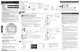
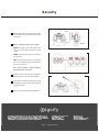
GENERAL WIRING DIAGRAM
CAUTION: Turn off electrical power at fuse or circuit breaker box before wiring fixture to the power supply.
page 1 www.stonco.com
CAUTION: For proper weatherproof function, all gaskets must be seated properly and all screws secured tightly.
Apply weatherproof silicone sealant around the edge of the wall box, especially on an uneven wall surface. Protect all plugs and
unused conduit entries.
Illustrations in the manual are for installation purpose only. Installation may vary depending on the specific luminaire model.
•Install and use only as intended according to UL, all applicable codes and regulations and these instructions.
•Put aside small parts and dispose packing material properly, to prevent hazard to children.
• All wiring connections must be capped with UL approved devices for this purpose.
•Always wear gloves and safety goggles when removing luminaires from carton, installing, servicing or performing maintenance.
•Avoid direct eye exposure to the illuminated light source.
• Verify that supplyvoltage is correct for the specified voltage range of the luminaire shown on the label, i.e. 120-277V.

Security
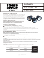
HARDWARE INCLUDED NOTE:Hardware not shown as the actual sizes.
MOUNTING INSTRUCTIONS
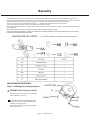
Step1: Installing the mounting bracket
page 2 www.stonco.com
DANGER: Risk of electric shock!
Disconnect power at fuse or by circuit breaker
before installing or sevicing.
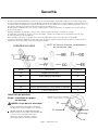
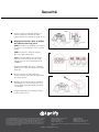
•Install the luminaire 70-98.5 in. When the lamp is installed at 98.5 inches and the angle between the PIR and the ground is 10
degrees, the detection distance is the farthest, about 472.5 inches, when the lamp is installed at a height of 70.9 inches, when the
angle between the PIR and the ground is 5 degrees, the detection The farthest distance is about 393.7 inches.
•Do not mount the luminaire near reflective surfaces, e.g., window,white wall,white surface and ice surface.
•When mounting the luminaire, make sure the PIR sensor orientate to the top.
Do not remove FF from mounting bracket.Line
up the holes on the mounting bracket(AA) with
the holes on the junction box.
Use screws to fasten the mounting bracket(AA)
onto the junction box.
•When the ambient temperature is higher than 35 degrees, the detection sensitivity will change. Especially close to human body
temperature, the detection will be insensitive.
•When mounting the luminaire onto a wall, make sure its central line 7 in. away from the eave and 13 in.away from the inner edge of
the adjacent wall.
•Avoid installing at the air outlet, air conditioner outlet, range hood outlet, away from WIFI.

page 3 www.stonco.com
Security
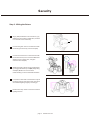
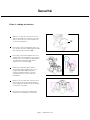
Step 2: Wiring the fixture
Align ( EE) installation foam with fixure, pay
attention to the position of outlet hole, and stick
it on the back cover of the lamp.
Connect the green wire on the luminaire with
the house ground wire by one wire nut (DD).
Connect the black wire on the luminaire with
the house line wire, and connect the white wire
with the house common wire, using the
other two wire nuts(DD).
Attach fixture(A) to the mounting bracket(AA)
by using(2) decorative cap nuts(BB) and(2) Oring
seals(CC).Make sure no loose wires
remain sticking out from underneath the fixture.
Loosen the screws with a screwdriver to adjust
the hinge angle of each lamp holder, then fix on
each desired lighting angle by screwing-up.
Rotate each lamp holder toward the desired
lighting direction.
EE

Security
page 4 www.stonco.com
Adjust the PIR sensor angle to get the best
sensing effect (the optimal detecting angle
is about 75°.
Adjust the CCT knob with a slot screwdriver
to point desired color temperature scale.
Apply silicone caulk around the edge of the
coverplate to provide a watertight seal from
rain and moisture.
Turn on power at the main fuse/breaker box.
Knobs' Setting for PIR sensor module
SENS To adjust sensor sensitivity and
response the distance between 2-12m
(25℃).
TIME To adjust the delay time (10 seconds
to 6 minutes).
LUX To activate PIR detection at daylight
mode or moonlight mode by the illuminance
from 2 lux to 2000 lux.
Knob default settings: highest sensitivity,
least lighting time, night mode.

page 1 www.keene.com
Sécurité
SL20-SCT-G1-8-BK
911401872081
Security
SL20-SCT-G1-8-BK
911401872081
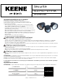
GENERAL SAFETY INFORMATION
Stonco Security luminaires bring high-quality, reliable safety to you. To avoid
hazards and unnecessary failures due to misuse, please read carefully all
warnings and instructions included in the MI sheets and all labels.
• Before installing, servicing, or performing routine maintenance upon this
equipment, pay attention to:supply voltage input 120-277V, frequency 50/60 Hz.
• This fixture is intended to be connected to a properly installed and grounded
UL listed junction box.
• Commercial installation, service and maintenance of luminaires should be
performed by a qualified licensed electrician.
• Residential installation, always consult a qualified licensed electrician and
check your local electrical code if any uncertainty before conduction.
• Always check the product before installation.
• DO NOT INSTALL DAMAGED PRODUCT!
WARNING: RISK OF ELECTRICAL SHOCK
• Always turn off the power before you perform installation and maintenance.
• Verify that supple voltage meet the adaption range of the luminaire shown on the label, i.e. 120-270V.
• Make all electrical and grounded connections in accordance with the National Electrical Code and any applicable local code
requirements.
• All wiring connections should be capped with UL approved wire connectors.
CAUTION: RISK OF INJURY
•Wear gloves and safety glasses at all times when removing luminaires from carton, installing, servicing or performing maintenance.
• Avoid direct eye exposure to the lit-on light source.
• Put aside small parts and dispose packing material properly, in case hazard to children.
CAUTION: RISK OF FIRE
•Keep combustible material away from the luminaires.
CAUTION: For proper weatherproof function, all gaskets must be seated properly and all screws secured tightly.
Apply weatherproof silicone sealant around the edge of the wall box, especially on an uneven wall surface. Protect all plugs and
unused conduit entries.
Illustrations in the manual are for installation purpose only. It may vary due to the different fixture purchased.
GENERAL WIRING DIAGRAM
CAUTION: Turn off electrical power at fuse or circuit breaker box before wiring fixture to the power supply.
page 1 www.stonco.com
Security
SL20-SCT-G1-8-BK
911401872081
GENERAL SAFETY INFORMATION
Stonco Security luminaires bring high-quality, reliable safety to you. To avoid
hazards and unnecessary failures due to misuse, please read carefully all
warnings and instructions included in the MI sheets and all labels.
• Before installing, servicing, or performing routine maintenance upon this
equipment, pay attention to:supply voltage input 120-277V, frequency 50/60 Hz.
• This fixture is intended to be connected to a properly installed and grounded
UL listed junction box.
• Commercial installation, service and maintenance of luminaires should be
performed by a qualified licensed electrician.
• Residential installation, always consult a qualified licensed electrician and
check your local electrical code if any uncertainty before conduction.
• Always check the product before installation.
• DO NOT INSTALL DAMAGED PRODUCT!
WARNING: RISK OF ELECTRICAL SHOCK
• Always turn off the power before you perform installation and maintenance.
• Verify that supple voltage meet the adaption range of the luminaire shown on the label, i.e. 120-270V.
• Make all electrical and grounded connections in accordance with the National Electrical Code and any applicable local code
requirements.
• All wiring connections should be capped with UL approved wire connectors.
CAUTION: RISK OF INJURY
•Wear gloves and safety glasses at all times when removing luminaires from carton, installing, servicing or performing maintenance.
• Avoid direct eye exposure to the lit-on light source.
• Put aside small parts and dispose packing material properly, in case hazard to children.
CAUTION: RISK OF FIRE
•Keep combustible material away from the luminaires.
CAUTION: For proper weatherproof function, all gaskets must be seated properly and all screws secured tightly.
Apply weatherproof silicone sealant around the edge of the wall box, especially on an uneven wall surface. Protect all plugs and
unused conduit entries.
Illustrations in the manual are for installation purpose only. It may vary due to the different fixture purchased.
GENERAL WIRING DIAGRAM
CAUTION: Turn off electrical power at fuse or circuit breaker box before wiring fixture to the power supply.
page 1 www.stonco.com
NOIR(+) ALIMENTATION
BLANC(-) COMMUN
VERTMISE À LA TERRE
Luminaire
INFORMATION GÉNÉRALE SUR LA SÉCURITÉ
Afin d’éviter les dangers et pannes inutiles suite
à une mauvaise utilisation, veuillez lire attentivement tous les
avertissements et directives inclus dans les fiches techniques MI
et sur toutes les étiquettes.
• Avant d’installer, de réparer ou d’effectuer un entretien de routine
sur cet appareil, bien prendre note de ce qui suit : entrée de tension
d’alimentation de 120-277V, fréquence 50/60 Hz
• Ce luminaire doit être installé correctement sur une boîte de jonction
homologuée UL et mise à la terre
• Dans une installation commerciale, le service et l’entretien des luminaires
doivent être effectués par un électricien sous licence qualifié
• Dans une installation résidentielle, toujours consulter un électricien sous
licence qualifié et bien vérifier votre code de l’électricité local si vous
avez un doute
• Toujours vérifier le produit avant l’installation
• NE JAMAIS INSTALLER UN PRODUIT ENDOMMAGÉ !
AVERTISSEMENT : RISQUE DE CHOC ÉLECTRIQUE
• Toujours couper l’alimentation avant d’installer ou d’entretenir
• S’assurer que la tension d’alimentation correspond à la plage de celle du luminaire indiquée sur l’étiquette, ex. : 120-270V
• Effectuer toutes les connexions électriques et de mise à la terre selon les exigences du Code de l’électricité national
et toutes les exigences du code local applicables
• Toutes les connexions de câblage devraient être recouvertes de capuchons de connexions homologués UL convenant à cette fin
ATTENTION : RISQUE DE BLESSURES
• Porter des gants et des lunettes de sécurité en tout temps lorsque vous sortez les luminaires des boîtes, que vous réparez
ou effectuez l’entretien
• Éviter tout contact direct entre les yeux et la source allumée
• Ranger toutes les petites pièces et jeter l’emballage puisqu’ils peuvent être dangereux pour les enfants
ATTENTION : RISQUE D’INCENDIE
• Installer et utiliser seulement en respectant les exigences d’UL, de tous les codes et réglementations applicables et selon ces
directives
ATTENTION : pour maximiser la fonction d’imperméabilité, tous les joints d’étanchéité doivent être positionnés correctement
et toutes les vis rattachées fermement.
Appliquer un joint de silicone imperméable sur tous les contours de la boîte de jonction surtout sur la surface du mur inégale.
Protéger tous les bouchons et les entrées de conduit non utilisées.
Les illustrations ici présentes ne servent que pour l’installation. L’installation peut varier selon le modèle spécifique
du luminaire.
DESSIN DE CÂBLAGE GÉNÉRAL
ATTENTION : couper l’alimentation au fusible ou au boîtier de disjoncteurs avant de raccorder le luminaire à l’alimentation.

Securité
Pièces Description Quantité
AA Support de montage 1
BB Écrous borgnes décoratifs 2
CC Joint torique d’étanchéité 2
DD Capuchons de connexions 3
EE Coussin de caoutchouc-mousse pour installation 1
Security
•Install the luminaire 70-98.5 in. high above the ground.
• Do not mount the luminaire near reflective surfaces, e.g., window,white wall,white surface and ice surface.
• When mounting the luminaire, make sure the PIR sensor orientate to the top.
• When mounting the luminaire onto a wall, make sure its central line 7 in. away from the eave and 13 in.away from the inner edge of
the adjacent wall.
HARDWARE INCLUDED NOTE:Hardware not shown as the actual sizes.
Part
AA
BB
CC
DD
EE
Description
Mounting bracket
Decorative cap nuts
O-ring seal
Wire nuts
Installation foam pad
Quantity
1
2
2
3
1
MOUNTING INSTRUCTIONS
Step1: Installing the mounting bracket
page 2 www.stonco.com
DANGER: Risk of electric shock!
Disconnect power at fuse or by circuit breaker
before installing or sevicing.
Line up the holes on the mounting bracket(AA)
with the holes on the junction box.
Use screws to fasten the mounting bracket(AA)
onto the junction box.
• Installer le luminaire de 70 à 98,5 po au-dessus du sol. Lorsque la lampe est installée à 98,5 pouces et que l’angle entre
le capteur infrarouge passif et le sol est de 10 degrés, la distance de détection est la plus éloignée, environ 472,5 pouces.
Lorsque la lampe est installée à une hauteur de 70,9 pouces et que l’angle entre le capteur infrarouge passif et le sol est
de 5degrés, la distance de détection la plus éloignée est de 393,7 pouces.
• Ne pas installer le luminaire près des surfaces réfléchissantes comme une fenêtre, un mur blanc, une surface blanche
et une surface glacée
• Pendant l’installation du luminaire, s’assurer que le capteur infrarouge passif est orienté vers le haut
• Si le luminaire est installé sur un mur, s’assurer que la ligne centrale soit éloignée de 7 po de l’avant-toit et de 13 po
de la bordure interne du mur adjacent
• Éviter d’installer près d’une sortie d’air, d’une sortie de climatisation, d’une sortie de hotte et loin du WiFi
• Lorsque la température ambiante est plus élevée que 35 degrés, la détection devient plus sensible. Surtout près de la
température du corps humain, la détection devient insensible
FERRURES INCLUSES NOTE : les ferrures illustrées ne démontrent
pas les formats réels.
DIRECTIVES DE MONTAGE
Étape 1 : installation du support
de montage
DANGER : risque de choc électrique !
page 2 www.keene.com
FF 2
Couper l’alimentation au fusible ou au boîtier
de disjoncteurs avant l’installation ou l’entretien.
Ne retirez pas FF du support de montage.
Aligner les trous sur le support de montagef (AA
) avec les trous sur la boîte de jonction.
Utiliser les vis pour rattacher le support
de montage (AA) sur la boîte de jonction.
Joint en silicone noir

page 3 www.keene.com
Securité
page 3 www.stonco.com
Security
Step 2: Wiring the fixture
Align ( EE) installation foam with fixure, pay
attention to the position of outlet hole, and stick
it on the back cover of the lamp.
Connect the green wire on the luminaire with
the house ground wire by one wire nut (DD).
Connect the black wire on the luminaire with
the house line wire, and connect the white wire
with the house common wire, using the
other two wire nuts(DD).
Attach fixture(A) to the mounting bracket(AA)
by using(2) decorative cap nuts(BB) and(2) Oring
seals(CC).Make sure no loose wires
remain sticking out from underneath the fixture.
Loosen the screws with a screwdriver to adjust
the hinge angle of each lamp holder, then fix on
each desired lighting angle by screwing-up.
Rotate each lamp holder toward the desired
lighting direction.
EE
EE
0°~90°
~90°
~90°
Aligner le coussin de caoutchouc-mousse
(EE) et le luminaire, bien vérifier la position
du trou de sortie et le coller à l’arrière du
couvercle du luminaire
Raccorder le fil vert du luminaire avec le fil
vert de mise à la terre d’alimentation à l’aide
d’un capuchon de connexion (DD)
Raccorder le fil noir du luminaire avec le fil
d’alimentation de l’immeuble et raccorder le
fil blanc avec le fil commun de l’alimentation
de l’immeuble à l’aide des deux autres
capuchons de connexion (DD)
Rattacher le luminaire (A) au support
de montage (AA) en utilisant (2) écrous
borgnes décoratifs (BB) et (2) joints
toriques d’étanchéité (CC). S’assurer
qu’aucun fil libre ne sorte en dessous
du luminaire
Dévisser les vis à l’aide d’un tournevis pour
ajuster l’angle de la charnière de chaque
porte-lampe puis ajuster l’angle d’éclairage
recherché en revissant
Faire pivoter chaque porte-lampe dans
la direction où l’éclairage est recherché
Étape 2 : câblage du luminaire

Securité
Security
Adjust the PIR sensor angle to get the best
sensing effect (the optimal detecting angle
is about 75°).
Knobs' Setting for PIR sensor module
SENS To adjust sensor sensitivity and
response the distance between 2-12m
(25℃).
TIME To adjust the delay time (10 seconds
to 6 minutes).
LUX To activate PIR detection at daylight
mode or moonlight mode by the illuminance
from 2 lux to 2000 lux.
Adjust the CCT knob with a slot screwdriver
to point desired color temperature scale.
Apply silicone caulk around the edge of the
coverplate to provide a watertight seal from
rain and moisture.
Turn on power at the main fuse/breaker box.
page 4 www.stonco.com
0°~180°
100°
120°
MUR
Capteur PIR Capteur PIR
Ajuster le capteur infrarouge passif pour
obtenir la meilleure captation possible
(l’angle de détection optimal est d’environ 75°)
Réglage des boutons pour le module
de capteur infrarouge passif
SENS Pour ajuster la sensibilité et la réponse
du capteur sur une distance entre 2 et 12 m
(25°C)
TIME Pour ajuster le temps de réponse
(de 10 secondes à 6minutes)
LUX Pour activer la détection infrarouge
passif en mode de lumière du jour ou de
clair de lune avec un éclairement de 2 lux
à 2 000lux
Réglages par défaut du bouton : sensibilité
la plus élevée, temps d’éclairage le plus faible,
mode nuit
Ajuster le bouton de TCP à l’aide d’un
tournevis à fente pour régler la température
de couleur désirée
Appliquer un joint de silicone sur la bordure
de la plaque de couvercle afin de procurer
un joint d’étanchéité imperméable à la pluie
ou l’humidité
Rétablir l’alimentation au fusible principal/
boîtier de disjoncteurs
© 2020 Signify Holding. Tous droits réservés. L’information retrouvée dans la présente
est sujette à changement sans préavis. Signify ne fait aucune déclaration ni ne donne
aucune garantie quant à l’exactitude et à l’exhaustivité des informations fournies
dans les présentes et ne serait être tenu responsable de toute mesure prise sur leur
fondement. Les informations présentées dans ce document ne constituent pas une
offre commerciale et ne font partie d’aucun devis ni contrat, à moins qu’il n’en soit
convenu autrement avec Signify.
Signify North America Corporation
200 Franklin Square Drive,
Somerset, NJ 08873
Téléphone 855-486-2216
Signify Canada Ltd.
281 Hillmount Road,
Markham, ON, Canada L6C 2S3
Téléphone 800-668-9008
Toutes les marques déposées appartiennent à SignifyHolding et à leurs propriétaires
respectifs.
page 4 www.keene.com
1176 11/18 page 4 de 3
-
 1
1
-
 2
2
-
 3
3
-
 4
4
-
 5
5
-
 6
6
-
 7
7
-
 8
8


Stonco Security Light Install Instructions
- Taper
- Install Instructions
- Ce manuel convient également à
dans d''autres langues
- English: Stonco Security Light