
power
Power midrange speakers
Operation & Installation
®
® ®
car audio
fanatics
for
RFR-1403
RFR-1404
RFR-1405
RFR-1406

Dear Customer,
Congratulations on your purchase of the world's finest brand of car audio speakers. At
Rockford Fosgate we are fanatics about musical reproduction at its best, and we are
pleased you chose our product. Through years of engineering expertise, hand craftsman-
ship and critical testing procedures, we have created a wide range of products that
reproduce music with all the clarity and richness you deserve.
For maximum performance we recommend you have your new Rockford Fosgate
product installed by an Authorized Rockford Fosgate Dealer, as we provide specialized
training through Rockford Technical Training Institute (RTTI). Please read your
warranty and retain your receipt and original carton for possible future use.
Great product and competent installations are only a piece of the puzzle when it comes
to your system. Make sure that your installer is using 100% authentic installation
accessories from Connecting Punch in your installation. Connecting Punch has
everything from RCA cables and speaker wire to Power line and battery connectors.
Insist on it! After all, your new system deserves nothing but the best.
To add the finishing touch to your new Rockford Fosgate image order your Rockford
wearables, which include everything from T-shirts and jackets to hats and sunglasses.
To get a free brochure on Rockford Fosgate products and Rockford accessories, in the
U.S. call 602-967-3565 or FAX 602-967-8132. For all other countries, call +001-602-
967-3565 or FAX +001-602-967-8132.
If, after reading your manual, you still have questions regarding this product,
we recommend that you see your Rockford Fosgate dealer. If you need further
assistance, you can call us direct at 1-800-795-2385. Be sure to have your serial
number, model number and date of purchase available when you call.
PRACTICE SAFE SOUND™
CONTINUOUS EXPOSURE TO SOUND PRESSURE LEVELS OVER
100dB MAY CAUSE PERMANENT HEARING LOSS. HIGH
POWERED
AUTOSOUND SYSTEMS MAY PRODUCE SOUND
PRESSURE
LEVELS WELL OVER 130dB. USE COMMON SENSE
AND
PRACTICE SAFE SOUND.
The serial number can be found on the outside of the box. Please record it in
the space provided below as your permanent record. This will serve as
verification of your factory warranty and may become useful in recovering your
product if it is ever stolen.
Serial Number: ________________________________
Model Number:________________________________

Welcome to Rockford Fosgate! This manual is designed to provide
information for the owner, salesperson and installer. For those of you
who want quick information on how to install this product, please turn
to the
Installation Section
of this manual or refer to the icon listed below.
Other information can be located by using the Table of Contents. We,
at Rockford Fosgate, have worked very hard to make sure all the
information in this manual is current. But, as we are constantly finding
new ways to improve our product, this information is subject to change
without notice.
GETTING STARTED
I
N
S
T
A
L
L
A
T
I
O
N
® ®
TABLE OF CONTENTS
Introduction .............................................................................................1
Package Contents.....................................................................................1
Technical Design Features ....................................................................... 1
Installation Considerations ....................................................................... 3
Installation ...............................................................................................4
Specifications...........................................................................................5
Warranty Information...............................................................................6
International Information..........................................................................7
Sections marked
INSTALLATION
include “slam dunk”
wiring connections

INTRODUCTION
This manual provides information on the features and installation of
the Punch Power Speakers. We suggest you save this manual for
future reference.
We strongly recommend you have your Authorized Rockford Fosgate
Dealer install the Punch Power Speakers. If you do choose to install
the speakers yourself, please be sure to read the entire manual before
beginning.
TECHNICAL DESIGN FEATURES
Installation & Operation Manual
(2) Midrange Speakers
(2) Speaker Grilles (1404/1405/1406)
(2) Speaker Grille Rings (1404/1405/1406)
(2) Speaker Grille Gaskets (1404/1405/1406)
(8) Phillips Mounting Screws (1404/1405/1406)
(4) Phillips Mounting Screws (1403)
PACKAGE CONTENTS
– 1 –
◆ TPR Surround
TPR (Thermal Plastic Rubber) is resilient to temperature variations and
provides a consistent support necessary of the linear motion of the
speaker cone. In addition, the inherent damping capabilities elimi-
nates the transmission of sonic disturbances between the cone and the
frame of the speaker. This greatly improves the clarity of the speaker's
midrange frequency response.
THE RESULT: Improves speaker's frequency response.
◆ Flat Spider
The speaker's linear compliance is balanced through the use of a
“proprietary” flat spider design. A flat spider provides symmetrical
control of the voice coil through its cone excursion. Linear cone
excursion reduces harmonic distortion for improved sound quality.
THE RESULT: Reduces mechanical distortion for better sound quality
.

– 2 –
◆ High Temperature Voice Coil
The voice coil is of a high temperature copper wire construction. The
wire is wound in two layers on a black, anodized, aluminum voice
coil former. The voice coil former dissipates heat away from the
voice coil improving the speaker's thermal stability and improving
the reliability of the speaker.
THE RESULT: Improves reliability by dissipating generated heat.
◆ Vented Pole Piece
The vented pole piece by design, ensures proper ventilation to cool
the voice coil and maintain lower operating temperatures. The vent
on the rear of the magnet reduces back pressure and allows cool air
to circulate in the voice coil gap. The air circulation increases the
thermal power handling of the speaker.
THE RESULT: Improves power handling by cooling the voice coil.
◆ Silver Powder Coat Finish
Powder coating has long been the industry standard for durability in
protective metal finishes. A dry powder (non-aerosol) is electrostati-
cally applied to the metal and “baked” on to provide a hard “shell-
like” finish. As an additional benefit, powder coating is the only
finishing process that releases no toxic chemicals into our ozone.
THE RESULT: A durable and “earth friendly” metal finish.

Tools Needed
The following is a list of some of the tools necessary for the installation
of your speakers.
Power Drill with assorted bits
Tape Measure
Voltmeter
#2 Phillips Screwdriver
General
1. For safety, disconnect the negative lead from the battery prior to
beginning the installation.
2. Never run wires underneath the vehicle. Running the wires inside
the vehicle provides the best protection.
3. Avoid running wires over or through sharp edges. Use rubber or
plastic grommets to protect any wires routed through metal.
4. Mount the speakers/crossovers away from electrical sources (other
than the amplifier) i.e.., power cables, electronic fuel pumps,
vehicle computers, and other potential noise sources.
5. Mount the speakers/crossovers away from areas of extreme heat or
moisture.
6. Make sure there is an area large enough of the speaker to mount.
Warning! Failure to do this can cause damage to the speaker if the
speaker frame is bent during installation.
7. Check to see that the location is deep enough for the speaker(s) and
the location does not interfere with the normal operation of the
vehicle.
8. When mounting the speaker(s) in the door of a vehicle, make sure
the speaker(s) do not interfere with either the door or window
operation.
9. When mounting the speaker(s) on the rear deck of the vehicle, check
the operation of the rear hatch or trunk lid. Make sure the torsion bars
and other moving parts are not obstructed by the speaker(s) instal-
lation.
• Please refer to the Specifications section of this manual for proper
mounting diameter and depth of the speaker(s).
– 3 –
INSTALLATION CONSIDERATIONS

INSTALLATION
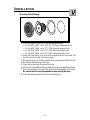
Mounting the Midrange
– 4 –
I
N
S
T
A
L
L
A
T
I
O
N
® ®
1. Cut the proper size hole for the midrange/woofer.
• For the RFR-1403, cut a 2 31⁄32" (75.4mm) diameter hole
• For the RFR-1404, cut a 3
13
⁄16" (96.8mm) diameter hole
• For the RFR-1405, cut a 4
7
⁄8" (123.8mm) diameter hole
• For the RFR-1406, cut a 5
5
⁄8" (142.9mm) diameter hole
2. Place the mounting ring over the mounting hole and mark the
location of the screw mounting holes.
3. Remove the ring. Drill the holes for the screws using a 1/8" drill bit.
4. Route the wire through the hole.
5. Place the mounting ring over the hole.
6. Attach the wires and be sure to observe the proper speaker polarity.
7. Place the speaker into the hole and screw the speaker into place.
Be careful not to bend the speaker frame during this step.
8. Press the speaker grille into the mounting ring.

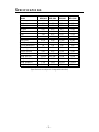
(Specifications are subject to change without notice)
– 5 –
Model RFR-1403 RFR-1404 RFR-1405 RFR-1406
Nom. Imped. 4 4 4 4
FS (Hz) 150 85 70 65
RE (Ohm) 3.6 3.9 3.8 3.3
LE (mH) 0.15 0.16 0.3 0.43
QMS 1.99 1.43 1.52 1.57
QES 2.02 0.47 0.37 0.34
QTS 1 0.36 0.3 0.28
VAS (cu.ft) 0.035 0.145 0.198 0.445
VAS (liter) 1 4.1 5.6 12.6
Power (Watts RMS) 80 100 120 120
SPL (dB @ 1w/1m) 84.5 89 89 93
X-MAX (inches) 0.02 0.05 0.06 0.09
X-MAX (mm) 0.4 1.2 1.6 2.4
Mntg. Dia. (in.) 2-31/32 3-13/16 4-7/8 5-5/8
Mntg. Dia. (mm) 75.40 96.80 123.80 142.90
Mntg. Depth (in.) 1-3/8 2-5/32 2-21/32 2-31/32
Mntg. Depth (mm) 34.90 54.80 67.50 75.40
SPECIFICATIONS

– 6 –
LIMITED WARRANTY INFORMATION
Ship to: Speakers
Rockford Acoustic Design
(Receiving-speakers)
609 Myrtle N.W.
Grand Rapids, MI 49504
RA#:_________________
Ship to: Electronics
Rockford Corporation
Warranty Repair Department
2055 E. 5th Street
Tempe, AZ 85281
RA#:_________________
Rockford Corporation offers a limited warranty on Rockford Fosgate products on the
following terms:
• Length of Warranty
1 year on speakers 30 days on speaker B-stock (receipt required)
3 years on electronics 90 days on electronic B-stock (receipt required)
2 years on source units
• What is Covered
This warranty applies only to Rockford Fosgate products sold to consumers by
Authorized Rockford Fosgate Dealers in the United States of America or its
possessions. Product purchased by consumers from an Authorized Rockford
Fosgate Dealer in another country are covered only by that country’s Distributor
and not by Rockford Corporation.
• Who is Covered
This warranty covers only the original purchaser of Rockford product purchased
from an Authorized Rockford Fosgate Dealer in the United States. In order to
receive service, the purchaser must provide Rockford with a copy of the receipt
stating the customer name, dealer name, product purchased and date of purchase.
• Products found to be defective during the warranty period will be repaired or
replaced (with a product deemed to be equivalent) at Rockford's discretion.
• What is Not Covered
1. Damage caused by accident, abuse, improper operations, water, theft
2. Any cost or expense related to the removal or reinstallation of product
3. Service performed by anyone other than Rockford or an Authorized Rockford
Fosgate Service Center
4. Any product which has had the serial number defaced, altered, or removed
5. Subsequent damage to other components
6. Any product purchased outside the U.S.
7. Any product not purchased from an Authorized Rockford Fosgate Dealer
• Limit on Implied Warranties
Any implied warranties including warranties of fitness for use and merchantability
are limited in duration to the period of the express warranty set forth above. Some
states do not allow limitations on the length of an implied warranty, so this
limitation may not apply. No person is authorized to assume for Rockford Fosgate
any other liability in connection with the sale of the product.
• How to Obtain Service
Please call 1-800-669-9899 for Rockford Customer Service. You must obtain an
RA# (Return Authorization number) to return any product to Rockford Fosgate. You
are responsible for shipment of product to Rockford.

INTERNATIONAL
INFORMATION
– 7 –

– 8 –
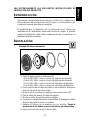
INSTALACIÓN
Montaje del altavoz de medios
I
N
S
T
A
L
L
A
T
I
O
N
® ®
1. Corte el agujero para el medio/woofer.
• Par el RFR-1403, corte un circulo de 75,4mm de díametro
• Par el RFR-1404, corte un circulo de 96,8mm de diámetro
• Par el RFR-1405, corte un circulo de 123,8mm de diámetro
• Par el RFR-1406, corte un circulo de 142,9mm de diámetro
2. Use los anillos de montaje de plástico como plantilla. Marque la
posición de los tornills de anclaje.
3. Quite el anillo y perfore los agujeros con una broca de 1/8".
4. Pase el cable de altavoz a través del agujero.
5. Monte el anillo de montaje sobre el agujero.
6. Conecte los cables observando la polaridad. Mantenga los cables
alejados pe partes móviles o cortantes.
7. Asegure el altavoz en la abertura con los tornillos. Tenga la
precaución de no doblar el marco del altavoz en este proceso.
8. Presione la rejilla en el anillo de montaje.
LEA DETENIDAMENTE LAS SIGUIENTES INSTRUCCIONES DE
INSTALACIÓN DEL PRODUCTO.
INTRODUCCIÓN
Este manual contiene información sobre la construcción, installación y
funcionamiento de los altovoces Punch Power. Le recomendamos que
conserve el manual para futuras consultas.
Es preferible que la instalación de los altovoces Punch Power sea
realizada por un distribuidor autorizado Rockford Fosgate. Si prefiere
realizar la instalación usted mismo, asegurese de leer el manual en su
totalidad antes de comenzar.
E
SPAÑOL

– 9 –
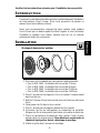
INSTALLATION
Montage du haut-parleur médium
1. Découper un trou adapté au haut-parleur médium/woofer.
• Pour le RFR-1403, le diamètre du trou est de 75,4mm
• Pour le RFR-1404, le diamètre du trou est de 96,8mm
• Pour le RFR-1405, le diamètre du trou est de 123,8mm
• Pour le RFR-1406, le diamètre du trou est de 142,9mm
2. Placer l'anneau de montage sur le trou et repérer l'emplacement
des trous des vis.
3. Retrirer l'anneau. Percer les trous des vis en utilisant une mèche de
3mm.
4. Faire passer les fils dans le trou central.
5. Placer l'anneau de montage au-dessus du trou central.
6. Connecter les fils au haut-parleur en respectant les polarités.
Eloigner les fils de toute partie tranchante ou mobile du véhicule.
7. Placer le haut-parleur au-dessus du trou central. Visser le haut-
parleur dans son emplacement. Faire attention à ne pas tordre le
chassis du haut-parleur durant cette étape de montage.
8. Mettre la grille dans l'anneau de montage.
Veuillez lire les instructions suivantes pour l'installation de ces produits.
INTRODUCTION
Ce manuel contient des informations sur les caractéristiques et l'installation
de haut-parleurs Punch Power. Nous vous proposons de garder ce
manuel pour toute référence future.
Nous vous recommandons vivement de faire installer votre système
Punch Power par un dealer agréé Rockford Fosgate. Si vous choisissez
d'installer le système vous même, assurez-vous de lire ce manuel
entièrement avant de commencer.
I
N
S
T
A
L
L
A
T
I
O
N
® ®
F
RANÇAIS

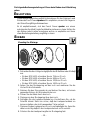
EINBAU
Mounting the Midrange
1. Schneiden Sie die richtige Lochgröβe für den Mitteltöner oder Midbaβ
aus.
• Für den RFR-1403, schneiden Sie ein 75,4cm ∅ Loch
• Für den RFR-1404, schneiden Sie ein 96,8cm ∅ Loch
• Für den RFR-1405, schneiden Sie ein 123,8cm ∅ Loch
• Für den RFR-1406, schneiden Sie ein 142,9cm ∅ Loch
2. Setzen Sie den Montagering auf das Loch und markieren Sie die
Löcher für die Schrauben.
3. Nehmen Sie den Ring wieder ab und bohren Sie dann, mit einem
passenden Bohrer, die Schraubenlöcher vor.
4. Führen Sie das Kabel durch das Loch.
5. Plazieren sie den Montagering über dem Loch.
6. Schlieβen Sie die Lautsprecherkabel an. Kontrollieren Sie, ob die
Polarität stimmt. Stelln sie sicher, daβ das Lautsprecherkabel an
keinen scharfen oder sich bewegenden Teilen anliegt.
7. Plazieren Sie den Lautsprecher im Loch und befestigen ihn. Seien Sie
dabei vorsichtig daβ sich der Lautsprecherkorb nicht verzieht.
8. Drücken Sie das Lautsprechergitter im Montagering fest.
Die folgende Bedienungsanleitung soll Ihnen beim Einbau eine Hilfestellung
geben.
ENLEITUNG
Diese Bedienungsaleitung enthält Informationen für den Gebrauch und
Einbau des Punch Power speakers. Wir empfehlen, sie auch für Fragen in
der Zukunft sorgfältig aufzubewahren.
Es ist empfehlenswert, sich das Punch Power speaker von einem
autorisierten Rockford Fosgte Fachhändler einbauen zu lasse. Sollten Sie
den Einbau jedoch selber vornehmen wollen, so empfehlen wir Ihnen
diese Bedienungsanleitung sorgfältig zu lesen.
I
N
S
T
A
L
L
A
T
I
O
N
® ®
D
EUTSCH
– 10 –

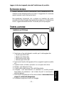
INSTALLAZIONE
Installazione el Midrange
1. Practicate un foro del diametro corretto per il midrange/woofer
• 75,4mm per RFR-1403
• 96,8mm per RFR-1404
• 123,8mm per RFR-1405
• 142,9mm per RFR-1406
2. Posizionate l'anello della griglia sul foro e segnate la posizione delle
viti.
3. Togliete l'enello e forate il pannello con una puna da 3,5mm.
4. Passate i cavi attraverso il foro.
5. L'anello della griglia sopra il foro dell'altoparlante.
6. Collegate i cavi assicurandovi di osservare la corretta polarità.
Assicuratevi di mantenere i cavi lontano da parti in movimento o
strutture taglienti.
7. Posizionate l'altoparlante nel foro ed avvitatelo. Assicuratevi di non
piegare il cestello dell'altoparlante.
8. Incastrate la griglia sull'anello di fissaggio.
Leggere le istruzioni seguenti prima dell'installazione del prodotto.
INTRODUZIONE
Questo manuale fornisce informazioni sulle caratteristiche e sul
installazione dei altoparlante Punch Power. Vi suggeriamo di conservare
questo manuale come riferimento futuro.
Raccomandiamo fortemente che is sistema sia installato dal vostro
rivenditore Rockford Fosgate. Se scegliete di procedere con l'installazione
da soli, leggete attentamente tutto il manuale prima di proseguire.
I
N
S
T
A
L
L
A
T
I
O
N
® ®
I
TALIANO
– 11 –


Rockford Fosgate
Rockford Corporation
546 South Rockford Drive
Tempe, Arizona 85281 U.S.A.
In U.S.A., (602) 967-3565
In Europe, Fax (49) 4207-801250
In Japan, Fax (81) 559-79-1265
LIT9598
12/96
MADE IN THE USA
This product is designed, developed and assembled in the USA by a dedicated
group of American workers. The majority of the components used in the
construction of this product are produced by American companies. However, due
to the global nature of their manufacturing facilities and the loudspeaker parts
industry in general, some parts may be manufactured in other countries.
-
 1
1
-
 2
2
-
 3
3
-
 4
4
-
 5
5
-
 6
6
-
 7
7
-
 8
8
-
 9
9
-
 10
10
-
 11
11
-
 12
12
-
 13
13
-
 14
14
-
 15
15
-
 16
16


Rockford Fosgate Punch Power RFR-1404 Operations & Installation Manual
- Taper
- Operations & Installation Manual
- Ce manuel convient également à
dans d''autres langues
Documents connexes
-
 Rockford Fosgate Punch Power RFR-1414 Operating & Installation Manual
-
 Rockford Fosgate Punch 100.2 Operations & Installation Manual
-
 Rockford Fosgate Punch RFA-614 Manuel utilisateur
-
 Rockford Fosgate Fanatic Q FNQ1414 Operation & Installation
-
 Rockford Fosgate Punch FNX2405 Manuel utilisateur
-
 Rockford Fosgate FNP2414 Manuel utilisateur
-
 Rockford Fosgate Fanatic X FNX2614 Installation & Operation Manual
-
 Rockford Fosgate Fanatic P FNP1614F Operation and Installation Manual
-
 Rockford Fosgate Fanatic FNQ2414 Operation & Installation
-
Rockford Fosgate 3-Way FNQ3146 Manuel utilisateur


