GE ZIF180NPKII Guide d'installation
- Catégorie
- Frigos
- Taper
- Guide d'installation

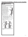
Installation
Instructions
18” and 24”Built-In Column
Freezers
24” and 30” Built-In Column
Refrigerators

2
31-49133-1
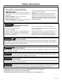
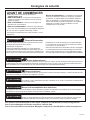
Safety Information
BEFORE YOU BEGIN
Read these instructions completely and carefully.
•
IMPORTANT – Save these instructions for
local inspector’s use. Observe all governing codes and
ordinances.
•
Note to Installer – Be sure to leave these
instructions with the Consumer.
• Note to Consumer – Keep these instructions with
your Owner’s Manual for future reference.
If you received a damaged unit, you should immediately
contact your dealer or builder.
Skill Level – Installation of this unit requires basic
mechanical, carpentry and plumbing skills. Proper
installation is the responsibility of the installer. Product
failure due to improper installation is not covered under
the Monogram Warranty. See the Owner’s Manual for
warranty information.
For Monogram local service in your area, call 1.800.444.1845 or visit monogram.com.
For Monogram service in Canada, call 1.800.561.3344
For Monogram Parts and Accessories, call 1.800.444.1845 or visit monogram.com.
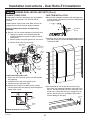
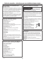
WARNING
Tip Over Hazard.
These appliances are top heavy, especially with any doors open, and must be secured to prevent tipping
forward which could result in death or serious injury. Read and follow the entire installation instructions for
securing the appliance with the anti-tip system.
WARNING
Explosion Hazard.
Keep flammable materials and vapors, such as gasoline, away from appliance. Failure to do so can result
in fire, explosion, or death.
WARNING
To reduce the risk associated with choking, do not allow children under 3 years of age to
have access to small parts during the installation of this product.
CAUTION
Lifting Hazard
This unit is very heavy. To reduce the risk of person injury during maneuvering and installing this appliance,
3 people are required for proper installation.
CAUTION
Keep fingers out of the “pinch point” areas; clearances between the doors and between the
doors and cabinet are necessarily small. Be careful closing doors when children are in the area.
WARNING
Electrical Shock Hazard.
Plug into a grounded 3-prong outlet.
Do not remove the ground prong.
Do not use an adapter.
Immediately discontinue use of a damaged supply cord.
If the supply cord is damaged it must be replaced by a
qualified service professional with an authorized service
part from the manufacturer.
Do not use an extension cord with this appliance.
Failure to follow these instructions can result in death,
fire, or electrical shock.
Follow the instructions in the section Grounding the unit.
This appliance must be installed with a means in the
fixed house wiring or circuit breaker for disconnecting the
appliance from the electrical supply after installation.

3
31-49133-1
Contents
Safety 2
Design Guide
Dimensions and Clearances 4
Accessories/Kits 5
Instructions for Dual Integrated Installation 6
The Installation Space 6
Tools, Hardware, Materials 8
Grounding the Unit 8
Flooring 8
Step 1. Remove Packaging 9
Step 2. Install Water Line 9
Step 3. Preparing Unit for Installation 10
Step 4. Install Anti-tip Bracket 11
Step 5. Joining Dual Installed Units 12
Step 6. Connecting Water Supply 13
Step 7. Inserting/Securing into Cabinet Surround 14
Step 8. Level Unit 15
Step 9. Final External Unit Preparation 15
Step 10. Internal Unit Preparation 16
Step 11. Start Icemaker 16
Step 12. Install AutoFill Pitcher Assembly 17
Instructions for Dual Retro-Fit Installation 18
The Installation Space 19
Tools, Hardware, Materials 20
Grounding the Unit 20
Flooring 20
Step 1. Remove Packaging 21
Step 2. Install Water Line 21
Step 3. Preparing Unit for Installation 22
Step 4. Install Anti-tip Bracket 23
Step 5. Joining Dual Installed Units 24
Step 6. Connecting Water Supply 26
Step 7. Inserting/Securing into Cabinet Surround 27
Step 8. Level Unit 28
Step 9. Final External Unit Preparation 28
Step 10. Internal Unit Preparation 29
Step 11. Start Icemaker 29
Step 12. Install AutoFill Pitcher Assembly 30
Instructions for Single Integrated Installation 31
The Installation Space 32
Tools, Hardware, Materials 33
Grounding the Unit 33
Flooring 33
Step 1. Remove Packaging 34
Step 2. Install Water Line 34
Step 3. Preparing Unit for Installation 35
Step 4. Install Anti-tip Bracket 35
Step 5. Connecting Water Supply 36
Step 6. Inserting/Securing into Cabinet Surround 36
Step 7. Level Unit 37
Step 8. Final External Unit Preparation 38
Step 9. Internal Unit Preparation 38
Step 10. Start Icemaker 38
Step 11. Install AutoFill Pitcher Assembly 39
Reversing the Door Swing 40
Step 1. Remove Door 41
Step 2. Remove Hinge Brackets 41
Step 3. Move Control Assembly 42
Step 4. Hove Light Switch Housing 42
Step 5. Reinstall Hinge Brackets 43
Step 6. Remove Hinges from Door 43
Step 7. Panel Brackets and Hinges 44
Step 8. Reinstall the Door 44
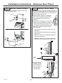
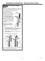
Stainless Steel Door Panel Installation 45
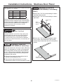
Step 1. Reversing Stainless Panel Door Swing 46
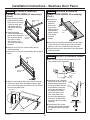
Step 2. Install Stainless Panel 47
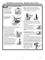
Step 3. Adjust Stainless Panel 48
Step 4. Install Hinge Covers 49
Step 5. Install Door Trims 49
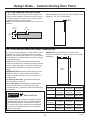
Custom Overlay Door Panel Installation 51
Custom Handle Design Guide 52
3/4” Custom Decorative Panel Dimensions 52
Step 1. Overlay Panel Prep 53
Step 2. Install Overlay Panel 54
Step 3. Adjust Overlay Panel 54
Step 4. Install Hinge Covers 55
Step 5. Install Door Trims 55

4
31-49133-1
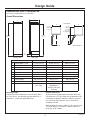
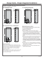
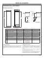
Design Guide
DIMENSIONS AND CLEARANCES
Dimensions in parentheses are in centimeters.
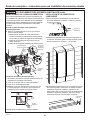
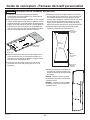
Product Clearances
These units are equipped with a 2-position door stop.
The factory set 115° door swing can be adjusted to 90°
if clearance to adjacent cabinets or walls is restricted.
For a 90° door swing, allow 4” (10.2 cm) minimum
clearance to a wall.
When installed in a corner, allow 15” (38.1 cm) for a full
115° door swing on 18” and 24” models. Allow 16.5”
(41.9 cm) on 30” models.
Shipping height.
The product can be adjusted to fit into a cutout that is
84” (213.36 cm). Use leveling legs and wheels for a
maximum 1” (2.54 cm) height adjustment.
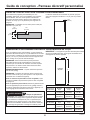
Overall Dimensions
FRONT VIEW SIDE VIEW
83-3/8"
(211.77)
C
83-1/4"
(211.46)
A
D
4"
(10.16)
TOP VIEWS
DOOR OPEN 90Û DOOR OPEN 115Û
E
F
B
4"
(10.16)
Minimum
to a Wall
B
15"
(38.1)
Minimum
to a Wall
(16.5"
(41.9)
on 30” models)
Dimensions 18” Models 24” Models 30” Models
A Overall Width - Front 17-1/2” (44.5 cm) 23-1/2” (59.7 cm) 29-1/2” (74.9 cm)
B Overall Width - Rear 17-1/4” (43.8 cm) 23-1/4” (59.1 cm) 29-1/4” (74.3 cm)
C Overall Depth 24-3/4” (62.9 cm) 24-3/4” (62.9 cm) 24-3/4” (62.9 cm)
D Case Depth 22-1/16” (56 cm) 22-1/16” (56 cm) 22-1/16” (56 cm)
E Door Clearance at 90° 21-1/4” (53.9 cm) 27-1/4” (62.9 cm) 33-1/4” (84.5 cm)
F Door Clearance at 115° 19-1/16” (48.4 cm) 24-1/2” (62.2 cm) 29-15/16” (76.0 cm)
Cutout Width 17-3/4” (45.1 cm) 23-3/4” (60.3 cm) 29-3/4” (59.7 cm)
Cutout Height 84” (213.4 cm) 84” (213.4 cm) 84” (213.4 cm)
Cutout Depth 25” (63.5 cm) 25” (63.5 cm) 25” (63.5 cm)
Weight 370 lbs
(167.8 kg)
460 lbs (208.7 kg)
(Refrigerator)
430 lbs. (195.0 kg)
(Freezer)
510 lbs (231.3 kg)

5
31-49133-1
Design Guide
7KH0RQRJUDP&ROXPQVUHIULJHUDWRUVDQGIUHH]HUVFDQEHLQVWDOOHGLQPDQ\FRQ¿JXUDWLRQV
ZLWKGLႇHUHQWLQVWDOODWLRQVLWXDWLRQV7KUHHLQVWDOODWLRQVLWXDWLRQVZLOOEHH[SODLQHGDORQJZLWK
door reversal instructions and two options for door panel installation.
Instructions for Dual Integrated Installation
New construction installation with 25” deep openings
Instructions for Dual Retro Installation
Existing construction installation (existing cutouts) with 24” deep openings that are 41-1/2” or 47-1/2” wide
Instructions for Single Integrated Installation
New construction installation with 25” deep opening
Reversing the Door Swing (all installation types)
Making a refrigerator LH swing and freezer RH swing
Instructions for Stainless Steel Door Panel Installation (all installation types)
Installing Stainless Steel Door Panel Kits
Instructions for Custom Overlay Door Panel Installation (all installation types)
Installing Custom Decorative Panels
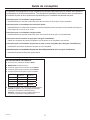
ACCESSORIES/KITS
Ŷ ZUGC+HDWHU8QL¿FDWLRQ.LW
Ŷ WX08X10006 8 Ft. Water Line
Ŷ ZTKC42 42” Trim Retro Kit
Ŷ ZTKC48 48” Trim Retro Kit
Ŷ 6WDLQOHVV6WHHO'RRU3DQHO.LWV
Ŷ Handle Kits for Custom Overlay Door Panels
ZKHCSS: Euro Tubular Stainless Steel Handle
GHVLJQHGWR¿W´RYHUOD\SDQHOV
ZKHPSS1: Pro Tubular Stainless Steel Handle
GHVLJQHGWR¿W´RYHUOD\SDQHOV
Unit Euro Handle Kits Pro Handle Kits
Ǝ/+ ZKCSC184 ZKCSP184
Ǝ/+ ZKCSC249 ZKCSP249
Ǝ5+ ZKCSC244 ZKCSP244
Ǝ5+ ZKCSC304 ZKCSP304

6
31-49133-1
Instructions for Dual Integrated Installation
New construction installation with 25” deep openings

7
31-49133-1
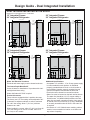
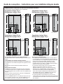
Design Guide - Dual Integrated Installation
18” Integrated Freezer
24” Integrated Refrigerator
DUAL INTEGRATED INSTALLATION SPACE
Dimensions in parentheses are in centimeters.
Water And Electrical Locations
Electrical and water supply must be located as shown.
The Cutout Depth Must Be 25”
Cutout is based on installation of 2 products with a left-
and-right hand door swing.
Heater Unification Kit ZUGC required.
Product Clearances
These units are equipped with a 2-position door stop.
The factory set 115° door swing can be adjusted to 90°
if clearance to adjacent cabinets or walls is restricted.
For a 90° door swing, allow 4” (10.2 cm) minimum
clearance to a wall.
When installed in a corner, allow 15” (38.1 cm) for a full
115° door swing on 18” and 24” models. Allow 16.5”
(41.9 cm) on 30” models.
Additional Specifications
• A separate 115 volt 60Hz., 15 or 20 amp power supply
is recommended for each product. An individual
properly grounded branch circuit or circuit breaker is
recommended. Install a properly grounded 3-prong
electrical receptacle recessed into the back wall.
Electrical must be located on rear wall as shown.
• Water line must be located on the back wall as shown.
The water line should be 1/4” O.D. copper tubing or
QuickConnect
™
kit (WX08X10006) between the cold
water line and water connection location, long enough
to extend to the front of the unit (8’ [2.4m]). Installation
of an easily accessible shut-off valve in the water line
is required.
• A minimum of 3-1/2” finished return matching cabinet
exterior is recommended on interior on all sides and
top at front of opening.
FRONT VIEW
84"
(213.4)
41 1/2" (105.4)
E
W
7 1/2”
(19.1)
4"
(10.2)
6 3/4"
(17.2)
2 1/2"
(6.4)
3 1/2"
(8.9)
4 1/8"
(10.5)
2"
(5.1)
ELEC W
4"
(10.2)
6 3/4"
(17.2)
2 1/2"
(6.4)
5"
(12.7)
22 1/8" (56.2)
27 1/4"
(69.2)
SIDE VIEW
25" (63.5)
3 1/2"
(8.9)
Finished
Return
Back
FRONT VIEW
84"
(213.4)
47 1/2"
(120.7)
E
W
7 1/2"
(19.1)
4"
(10.2)
6 3/4"
(17.2)
6 3/4"
(17.2)
2 1/2"
(6.4)
2 1/2"
(6.4)
3 1/2"
(8.9)
4 1/8"
(10.5)
2"
(5.1)
ELEC W
6 1/4"
(10.2)
5"
(12.7)
22 1/8" (56.2)
28" (71.1)
SIDE VIEW
25" (63.5)
3 1/2"
(8.9)
Finished
Return
Back
FRONT VIEW
84"
(213.4)
47 1/2"
(120.7)
ELEC W
9 1/2"
(24.1)
4
6 3/4"
(17.2)
4 3/8"
(11.1)
ELEC W
4"
(10.2)
6 3/4"
(17.2)
2 1/2"
(6.4)
2 1/2"
(6.4)
5"
(12.7)
5"
(12.7)
28 1/8" (71.4)
33 1/4" (84.5)
SIDE VIEW
25" (63.5)
3 1/2"
(8.9)
Finished
Return
Back
84"
FRONT VIEW
84"
(213.4)
53 1/2" (134.6)
ELEC W
9 1/2"
(24.1)
4"
(10.2)
4 3/8"
(11.1)
ELEC W
6 1/4"
(15.9)
6 3/4"
(17.2)
6 3/4"
(17.2)
2 1/2"
(6.4)
5"
(12.7)
2 1/2"
(6.4)
5"
(12.7)
28 1/8" (71.4)
34" (86.4)
25
SIDE VIEW
25" (63.5)
3 1/2"
(8.9)
Finished
Return
Back
18” Integrated Freezer
30” Integrated Refrigerator
24” Integrated Freezer
24” Integrated Refrigerator
24” Integrated Freezer
30” Integrated Refrigerator

8
31-49133-1
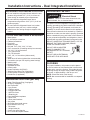
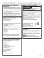
Installation Instructions - Dual Integrated Installation
TOOLS AND MATERIALS REQUIRED
• Metal shears
• #1, #2 Phillips screwdriver
• Flathead screwdriver
• Putty knife
• Measuring tape
• Drill and 1/16”, 5/64”, 3/16”, 1/2” bits
• 5/32” concrete bit (if installing anti-tip into concrete)
• 1/4”, 3/8”, 7/16” driver/socket
• 7/16” open wrench
• T20, T30 driver/bit
• 5/64”, 1/8”, 1/4” hex driver (allen wrench)
• Level
• Water shut-off valves (optional but recommended)
• 8’ waterline (one per unit requiring water hookup)
• Masking tape
• Rubbing alcohol
• Adjustable wrench
• Center punch
• Heater Unification Kit (ZUGC)
• Stainless Steel Door Kits (if applicable)
• Custom panels for doors (if applicable)
• Handle Kits (if applicable)
HARDWARE SUPPLIED (per unit)
• Water Filter Bypass Plug (if equipped)
• Air filter (if equipped)
• Anti-Tip bracket
• 3 Lag screws
• 3 Tapcon screws
• 3 Toggles with bolts
• 1 Hair Pin Cotter
• 1 Retaining pin
• Panel installation templates
• 2 Door trims
• 2 Door panel brackets
• Set screws
• #6 Phillips head wood screws
• Door Bracket Cover Top
• T30 screws
• 1 Hinge limiter pin
• Center door panel bracket
• Hi-Lo screw and square washer
FLOORING
For proper installation, this product must be placed
on a level surface of hard material that is at the same
height as the rest of the flooring. This surface should
be strong enough to support a fully loaded refrigerator
or freezer, or approximately 1,200 lbs. per unit.
NOTE: Protect the finish of the flooring.
NOTE: Not recommended for installation on carpeted
flooring.
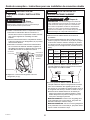
GROUNDING THE UNIT
The power cord of this appliance is equipped with a
3-prong (grounding) plug which mates with a standard
3-prong (grounding) wall receptacle to minimize the
possibility of electric shock hazard from this appliance.
Have the wall outlet and circuit checked by a qualified
electrician to make sure the outlet is properly grounded.
Where a standard 2-prong wall outlet is encountered, it
is your personal responsibility and obligation to have it
replaced with a properly grounded 3-prong wall outlet.
DO NOT, UNDER ANY CIRCUMSTANCES, CUT OR
REMOVE THE THIRD (GROUND) PRONG
FROM THE POWER CORD.
DO NOT USE AN ADAPTER
PLUG TO CONNECT THE
REFRIGERATOR TO A 2-PRONG
OUTLET.
DO NOT USE AN EXTENSION
CORD WITH THIS APPLIANCE.
REFRIGERATOR/FREEZER LOCATION
Ŷ Do not install the refrigerator/freezer where the tem-
perature will go below 55°F (13°C). It will not run
often enough to maintain proper temperatures.
Ŷ Do not install the refrigerator/freezer where
temperatures will go above 100°F (37°C). It will not
perform properly.
Ŷ Do not install the refrigerator/freezer in a location
exposed to water (rain, etc.) or direct sunlight.
Ŷ Install it on a floor strong enough to support it fully
loaded.
WARNING
Electrical Shock
Hazard.
Failure to follow these instructions can
result in death, fire, or electrical shock.

9
31-49133-1
Installation Instructions - Dual Integrated Installation
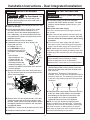
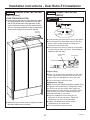
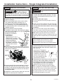
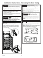
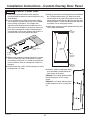
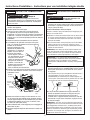
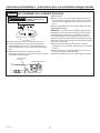
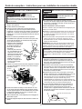
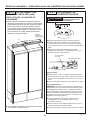
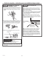
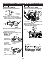
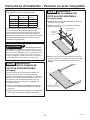
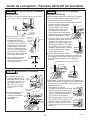
STEP 1 REMOVE PACKAGING
Ŷ Remove outer carton and external packing from units.
Ŷ Inspect for damage.
Ŷ Ensure the flooring that the units are set is clean/
free of debris that could be collected on to, or
pinched in front of the wheels and damaging the
floor. Additionally, it is recommended that the floor
be protected with a plastic covering through out the
installation process.
Ŷ Remove hardware kit from top drawer.
Ŷ If installation requires a 90° door opening, the
hinge limiter pin must
be installed in the top
hinge BEFORE the unit is
removed from the skid. Pin
is located in the hardware
kit.
- Open the door
approximately 45°, but
no wider than 90°, to
expose the hole in the
back hinge bracket and
install the limiting pin. Pin
must be fully seated in the bracket or the door will
not close properly.
Ŷ Remove front access cover from unit by removing 2
T20 Torx screws. Place the cover and screws to the
side for future installation.
Ŷ Remove three 3/8” drive screws and two 7/16” drive
screws from each side of the unit to release it from
the skid. Tip the unit from the side enough to remove
the shipping material from under the unit, but above
the skid (both sides)
Ŷ CAREFULLY roll the unit off the back side of the skid.
Ŷ Handle from side only with a hand truck.
Shipping
Bracket
7/16” Drive
Screws
T20 Torx
Screws
3/8” Drive
Screws
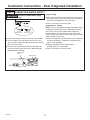
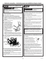
STEP 2 INSTALL WATER LINE
Ŷ A cold water supply is required for automatic
icemaker and AutoFill pitcher operation. The water
pressure must be between 40 and 120 p.s.i. (275-
827 kPa).
Shut off the main water supply.
Turn on the nearest faucet long enough to clear the
line of water.
ŶInstall a shut-off valve between the water valve and
cold water pipe in a basement or cabinet. The shut-
off valve should be located where it will be easily
accessible.
ŶTurn on the main water supply and flush debris.
Run about a quart of water through the tubing into a
bucket. Shut off water supply at the shut-off valve.
NOTE: Saddle type shut-off valves are included in
many water supply kits. Before purchasing, make sure
a saddle type valve complies with your local plumbing
codes.
NOTE: Commonwealth of Massachusetts Plumbing
Codes 248CMR shall be adhered to. Saddle
valves are illegal and use is not permitted in
Massachusetts. Consult with your licensed plumber.
Ŷ Route 1/4” OD copper or SmartConnect
™
(WX08X10006) plastic tubing between house cold
water line and the water connection location at the
front of the unit.
SmartConnect
™
Refrigerator Tubing Kits are
available. One 8’ (2.4m) water line (WX08X10006) is
needed for each unit. The waterline(s) will be taped
to the floor using masking tape after anti-tip bracket
installation.
Ŷ Tubing should be long enough to extend to the front
of the unit. Allow enough tubing to accommodate
bend leading into the water line connection. Unit
must be tipped on its side to route waterline
underneath and to the front of the appliance.
NOTE: The only GE Appliances approved plastic
tubing is supplied in the SmartConnect
™
Refrigerator
Tubing kits. Do not use any other plastic water supply
line because the line is under pressure at all times.
Other types of plastic may crack or rupture with age
and cause water damage to your home.
Top
Hinge
WARNING
Connect to potable water supply
only.
WARNING
Tip Over Hazard. This
appliance is top heavy. Use extreme caution with
moving to prevent tipping over which could result in
death or serious injury.

10
31-49133-1
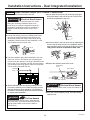
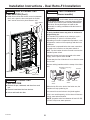
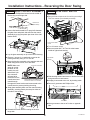
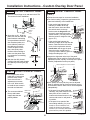
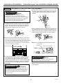
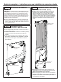
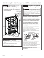
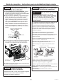
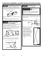
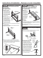
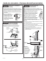
STEP 3 PREPARING UNIT FOR INSTALLATION
Ŷ Place the right hand unit in front of the installation
opening in a way that the unit is in front of the intended
installed location.
Ŷ If doors will be reversed after installing, the stabilization
bracket at the top hinge side of the case will need to
be moved to the opposite side of the case. Remove 4
Phillips head screws, rotate the stabilization bracket
and install on the opposite side of the case.
Ŷ Unpack the heater Unification Kit (ZUGC) and make
sure all of the components on the list are included.
Ŷ Install 4 bumper blocks by snapping them to the left
side of the case between the 2 units - 2 on the upper
section of the case wall and 2 on the lower.
Ŷ Install adhesive heater on the outside of the unit to
the left side of the case. Install heater 2” below the top
2 standoff blocks. Heater should be centered front to
back on the metal case. Ensure the heater connector
cord is toward the bottom of the unit when installed.
Ŷ Remove the left access cover by removing 4 (1/4”) hex
screws. The cover is located at the outside lower left
side of the case.
Ŷ Use clips to adhere loose wire tightly to side of case as
shown. Clean the side using rubbing alcohol to ensure
proper clip adhesion.
Installation Instructions - Dual Integrated Installation
Upper bumpers
Lower bumpers
Stabilization
Bracket
Ǝ
Adhesive
Heater
Clips
Hex
Screws
Left Access
Cover

11
31-49133-1
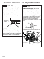
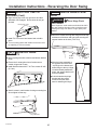
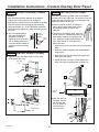
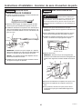
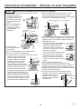
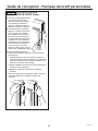
STEP 3 PREPARING UNIT FOR
INSTALLATION (Cont.)
Ŷ Install the transformer into the machine compartment:
1. Plug transformer into the 3 pin connector at the top
of the machine compartment. Make sure locking
tabs are engaged.
2. Place the transformer into the machine compartment
and secure it with the 2 (1/4”) hex screws provided
in ZUGC kit.
3. Connect the 2 pin transformer connector to the
heater connector, make sure locking tabs are
engaged, and place in wire clip at the top of the
machine compartment.
Ŷ Replace the left access cover and 4 (1/4”) hex
screws.
Installation Instructions - Dual Integrated Installation
WARNING
Electrical Shock
Hazard. To avoid the risk of electric shock, make
sure the power cord is not plugged into the wall
outlet.
2 Pin
Connector
to Heater
Connector
3 Pin
Connector
Transformer
1
3
2
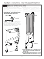
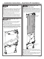
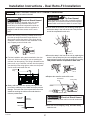
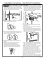
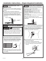
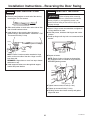
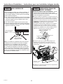
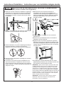
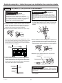
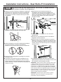
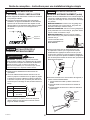
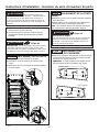
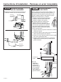
STEP 4
INSTALL ANTI-TIP BRACKET
Ŷ Remove the anti-tip bracket from the hardware kit.
Ŷ Anti-tip bracket should be mounted against the back
wall or up to 27” (68.6 cm) maximum from front of
opening. Use floor mounting method if the bracket is
not against a wall (bracket hardware is provided for
mounting into wood, steel studs and concrete).
Ŷ Measure and mark from the LH side of the opening
per the table above depending on the size of the LH
unit you are installing.
Ŷ Measure and mark again from the LH side of the
opening per the table and depending on your
combination of LH and RH units.
For example, if installing an 18” LH unit and a 30” RH
unit, use 10-7/8” and 37-3/4”.
LH Unit
RH Unit
WARNING
Tip Over Hazard.
These appliances are top heavy, especially with
any doors open, and must be secured to prevent
tipping forward which could result in death or seri-
ous injury. Read and follow the entire installation
instructions for securing the appliance with the
anti-tip system.
Unit LH Unit
RH Units
18” 24” 30”
18” 10-7/8”
(27.62cm)
29-3/4”
(75.57 cm)
33-3/4”
(85.73 cm)
37-3/4”
(95.89 cm)
24” 14-7/8”
(37.78cm)
33-3/4”
(85.73 cm)
39-3/4”
(100.97cm)
43-3/4”
(110.49cm)
30” 18-7/8”
(47.95cm)
37-3/4”
(95.89 cm)
45-3/4”
(116.21cm)
49-3/4”
(126.37cm)

12
31-49133-1
Installation Instructions - Dual Integrated Installation
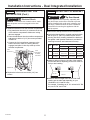
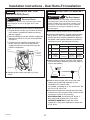
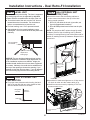
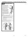
STEP 4
INSTALLING ANTI-TIP
BRACKET
(Cont.)
Ŷ Mount the anti-tip bracket centered about the marks
and flush to the floor as shown. Mark 3 holes for wall
mounting or 4 holes for floor mounting.
WOOD MOUNTING: Predrill with 3/16” drill bit, 2”
deep, then install lag bolts with a 7/16” driver.
CONCRETE MOUNTING: Predrill with a 5/32”
concrete bit, 2” deep, then install tapcon screws with
a 7/16” driver.
STEEL MOUNTING: Predrill with a 1/2” drill bit, insert
toggle, then install bolts with a 7/16” driver.
The bracket must be screwed to either the FLOOR or
REAR WALL.
Ŷ Tape the waterline to the wall and floor approximately
3” to the left of the anti-tip bracket. Apply tape about
every 5” toward the front of the opening (tape will
prevent the unit from rolling over the waterline during
installation). Do not tape near the cabinet front in
order to keep tape hidden under the unit.
Ŷ Route the strapping coiled up at the back of the unit
through the anti tip bracket.
1. Cut the wire tie holding the strap bundle.
2. Put the strap on the backside of the retaining pin.
3. Secure the retaining pin to the bracket with the
cotter pin.
4. Repeat strap routing on the second unit.
Retaining
Pin
Cotter
Pin
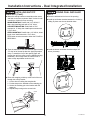
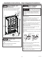
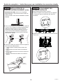
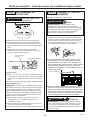
STEP 5
JOINING DUAL INSTALLED
UNITS
Ŷ Place the left hand unit in front of the opening.
Ŷ Install top unification bracket between the 2 units by
sliding in place over the two shoulder bolts.
Ŷ Install the bottom unification bracket using a 3/8”
driver (4 screws).
3"
5"
3"
5"

13
31-49133-1
Installation Instructions - Dual Integrated Installation
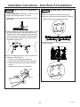
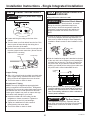
STEP 6
CONNECTING WATER SUPPLY
Ŷ Locate and bring the tubing to the front of the cabinet.
Ŷ Turn the water on to flush debris from the line. Run
about a quart of water through the tubing into a bucket,
then shut off the water.
Ŷ Remove strain relief screw to allow for enough slack
to make a proper water connection. (Screw must be
replaced in the next step.)
Copper Tubing:
Ŷ Slip a 1/4” nut and ferrule (provided) over both ends of
the copper tubing. Insert the tube into the union fitting
on the unit and tighten the nut to the union.
Ŷ Turn on the water to check for leaks.
SmartConnect
™
Tubing:
NOTE: The only GE Appliances-approved plastic tubing
is supplied in the SmartConnect
™
Refrigerator Tubing
kits. Do not use any other plastic water supply line
because the line is under pressure at all times. Other
types of plastic may crack or rupture with age and cause
water damage to your home.
Ŷ Insert the molded end of the tubing into the refrigerator
or freezer connection. Tighten the compression nut
until it is just hand-tight.
Ŷ Tighten one additional turn with a wrench.
Overtightening can cause leaks!
Ŷ Turn on the water to check for leaks.
Strain Relief
Screw
Anti-tip Strap
Freezer
Water Supply
House
Water Supply
Refrigerator/
Freezer
Water Supply
WARNING
Connect to potable water supply
only.

14
31-49133-1
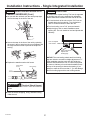
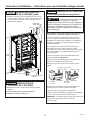
STEP 7
INSERTING/SECURING INTO CABINET SURROUND
Ŷ Plug both units into the outlet in the wall.
Ŷ Loosen the strap by removing a Phillips head screw
from the top strap bar and the large tensioner 1/4”
allen screw to allow the strap to move freely during
installation. Retain screws for later installation in this
step. Repeat process for both units.
Ŷ Find the installation string that is attached to the door
of the unit; this is to be used as you are pushing the
unit back into the opening. The string is attached to the
power cord; as you walk the unit back into the opening
you should pull the string tight to make sure the power
cord is routed underneath the unit.
Ŷ Slowly walk both units into opening making sure not
to touch the cabinetry on the sides and top to prevent
damage. Both door faces should be 7/8” behind the
front face of surrounding cabinets on either a stainless
or custom panel installation.
Ŷ As you walk the unit back, pull the anti-tip strap tight.
Secure the strap in the front of the unit. This process
should be completed for each unit.
Ŷ Secure the strap in the front of the unit by replacing the
screw in the top strap bar (do not overtighten) and the
large tensioner screw to prevent the strap from moving.
This process must be completed for both units.
Ŷ Replace the waterline strain relief screw.
Ŷ Store the excess strapping, string, and water tubing
under the unit.
Installation Instructions - Dual Integrated Installation
WARNING
Tip Over Hazard.
These appliances are top heavy, especially with
any doors open, and must be secured to prevent
tipping forward which could result in death or
serious injury.
WARNING
Electrical Shock Hazard.
Replace waterline strain relief in front rail location as
shown.
WARNING
Electrical Shock Hazard.
To reduce the risk of electrical shock, be careful
during the remaining installation steps not to
touch wiring or electrical components inside the
compressor compartment while the appliance is
plugged in and the front access cover is not in
place.
Installation
String
Strain Relief
Screw
Anti-tip Strap

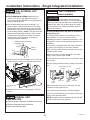
15
31-49133-1
Installation Instructions - Dual Integrated Installation
STEP 8 LEVEL UNIT
All models have 4-point leveling. The front is supported
by leveling legs; the rear is supported by adjustable
wheels. Both are accessible from the front of the unit.
Ŷ To level the back of the unit, turn the 7/16” hex nut
located above the front wheels. Turn clockwise to
raise or counterclockwise to lower the unit.
Ŷ For front leveling, use a 7/16” open-end wrench.
Ŷ Adjust height of unit to match installation cutout
opening 84”. The unit should be level and plumb with
cabinetry.
NOTICE: The rear leveling wheels and front leveling
legs are limited to a maximum height adjustment of 1”.
If the installation requires more than 84” height, the
installer should elevate the unit on a sheet of plywood
or runners. Cabinetry trim could also be added across
the top of the opening to shorten the opening. If you
attempt to raise the unit more than 1”, you will damage
the front leveling legs and the rear leveling wheels.
Hex nut adjusts
rear wheels
Open-end wrench
adjusts front
leveling legs
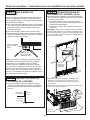
STEP 9
FINAL EXTERNAL UNIT
PREPARATION
Ŷ FOR FLUSH INSTALLATION: Make sure front
surface of the door is 7/8” behind front face of
surrounding cabinets BEFORE securing brackets to
the surrounding cabinetry.
Ŷ Secure stabilization brackets by predrilling 1/16”
holes in both the side and top surround 1/2” deep
through holes in the bracket. Drive 4 No. 6 Phillips
head screws to secure the unit stabilization bracket
to surrounding cabinetry. NOTE: This step does NOT
replace the anti-tip safety hardware. Refer to Step
4 Installing Anti-Tip Bracket and Step 7 Inserting/
Securing into Cabinet Surround for details on
installing the anti-tip hardware. Repeat for the second
unit.
Ŷ Open doors to make sure lights are on. If they are
not on, check to make sure the master switch is on.
Ŷ Install front access covers by replacing 2 T20 Torx
screws on each cover.
Stabilization Bracket already
installed to unit
Cabinet
surround
Master
Switch
T20 Torx Screws
Front Access
Cover

16
31-49133-1
Installation Instructions - Dual Integrated Installation
STEP 9
FINAL EXTERNAL UNIT
PREPARATION (Cont.)
Ŷ Install front mullion and access cover trims between
the 2 units. Open the doors and push the flexible
“dart” area of the trims in place between units.
STEP 10 INTERNAL UNIT
PREPARATION
Ŷ Remove all tape, cardboard, and foam from each
unit.
Ŷ Remove boxed door bins from shelves.
Ŷ Unbox and install door bins.
STEP 11 START ICEMAKER
(freezer models)
A newly-installed freezer may take 12–24 hours to
begin making ice.
The icemaker will produce seven cubes per cycle—
approximately 15 cycles in a 24-hour period,
depending on freezer compartment temperature, room
temperature, number of door openings and other use
conditions.
If the freezer is operated before the water connection
is made to the icemaker, set the power switch to
OFF. Top wire basket must be removed to access the
icemaker power switch.
When the freezer has been connected to the water
supply, set the power switch to
ON
.
Throw away the first full bucket of ice to allow the water
line to clear.
Be sure nothing interferes with the sweep of the feeler
arm.
When the bin fills to the level of the feeler arm, the
icemaker will stop producing ice.
It is normal for several cubes to be joined together.
If ice is not used frequently, old ice cubes will become
cloudy, taste stale and shrink.
NOTE: Icemaker works best between 40 and 120 PSI
(275-827 kPa) home water pressure.
Feeler Arm
Feeler Arm
Icemaker
Icemaker
Power
Switch
Power
Switch
(Appearance may vary)
Lower
Mullion Trim
“Dart”
Upper Mullion
Trim
“Dart”
CAUTION
Avoid contact with the moving parts
of the ejector mechanism, or with the heating element
(located on the bottom of the icemaker) that releases
the cubes. Do not place fingers or hands on the
automatic ice making mechanism while the freezer is
plugged in.

17
31-49133-1
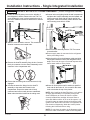
Installation Instructions - Dual Integrated Installation
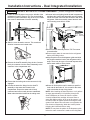
STEP 12 INSTALL AUTOFILL PITCHER ASSEMBLY (Some Refrigerator Models)
Ŷ Locate the AutoFill pitcher cover on the left side of the
refrigerator’s interior. Remove T20 Torx screw holding
the cover in place towards the rear of the cover. Retain
this screw for attachment of AutoFill assembly.
Ŷ Slide the cover forward to remove. This reveals an
electrical connector and a water tube.
Ŷ Remove the AutoFill assembly from the box. Connect
the 4 pin connector from the AutoFill assembly to the
connector in the compartment wall.
Ŷ Ensure that the locking tab on the connector is fully
engaged.
Ŷ Connect the water line fitting from the AutoFill
assembly to the water tube located in the
compartment. Ensure the water tube is firmly
connected and will not easily become unattached.
Water tube should be inserted to the tubing mark.
Ŷ Conceal wires and tubing inside the wall compartment
and place the AutoFill wall assembly onto the forward
end of the mount until flush with the interior wall of the
refrigerator. Slide the assembly toward the back wall
until mounting screw hole is visible.
Ŷ Secure AutoFill assembly with the T20 Torx screw
removed earlier.
Ŷ Ensure supply water is connected to the refrigerator
before proceeding further.
Ŷ Align the pitcher lid to the dispenser guide and slide
the pitcher toward the back of the refrigerator until it
stops. There may be up to a 5 second response time
before water starts to fill the pitcher.
Ŷ Water will fill the pitcher until it reaches a specified
level and will then shut off. It is normal for the water
level to be below the top of the pitcher.
NOTE: After installing the AutoFill pitcher, run 2 gallons
of water (approximately 5 full pitchers) through the
AutoFill dispenser to remove air from the system.
A newly installed filter cartridge will cause water to
spurt and dribble until the air is out of the system. It is
normal for water to appear discolored during the initial
system flush. Water color will return to normal after the
first minutes of dispensing. Wash the AutoFill pitcher
following the initial flush before using.
NOTE: Do not place the pitcher in the dispenser guide
before the water connection is made to the refrigerator.
Screw
AutoFill
Assembly
Mount
Compartment
Screw
Cover

18
31-49133-1
Instructions for Dual Retro-Fit Installation
Existing construction installation with 24” deep openings
that are 41-1/2” or 47-1/2” wide

19
31-49133-1
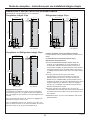
FRONT VIEW SIDE VIEW
W
24" (61.0)
3/4"
(1.91)
E
WATER
47 1/2" (120.7)
20" (50.8)
*
83 1/2" min
*
84 1/2" max
(212.1-214.6)
*
Trim will overlap
additional 7/16 "
3 1/2"
(8.9)
75"
(190.5 )
From floor
to bottom
of electrical
area
6"
(15.2)
5"
(12.7)
5"
(12.7)
5"
(12.7)
FRONT VIEW SIDE VIEW
W
24" (61.0)
3/4"
(1.91)
E
WATER
41 1/2" (105.4)
18" (45.7)
*83 1/2" min
*84 1/2" max
(212.1-214.6)
*Trim will overlap
additional 7/16 "
3 1/2"
(8.9)
75"
(190.5 )
From floor
to bottom
of electrical
area
6"
(15.2)
5"
(12.7)
5"
(12.7)
5"
(12.7)
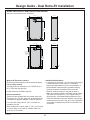
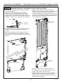
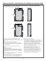
DUAL RETRO-FIT INSTALLATION SPACE
Dimensions in parentheses are in centimeters.
Design Guide - Dual Retro-Fit Installation
Water And Electrical Locations
Electrical and water supply must be located as shown.
For 24” Deep Cutouts
Trim Retro kits are required for a 41.5”(ZTKC42) or a
47.5” (ZTKC48) wide opening.
Heater Unification Kit ZUGC required
Product Clearances
These units are equipped with a 2-position door stop.
The factory set 115° door swing can be adjusted to 90°
if clearance to adjacent cabinets or walls is restricted.
For a 90° door swing, allow 4” (10.2 cm) minimum
clearance to a wall.
When installed in a corner, allow 15” (38.1 cm) for a full
115° door swing on 18” and 24” models. Allow 16.5”
(41.9 cm) on 30” models.
Additional Specifications
• A separate 115 volt 60Hz., 15 or 20 amp power supply
is recommended for each product. An individual
properly grounded branch circuit or circuit breaker is
recommended. Install a properly grounded 3-prong
electrical receptacle recessed into the back wall.
Electrical must be located on rear wall as shown.
• Water line must be located on the back wall as shown.
The water line should be 1/4” O.D. copper tubing or
QuickConnect
™
kit (WX08X10006) between the cold
water line and water connection location, long enough
to extend to the front of the unit (8’ [2.4m]). Installation
of an easily accessible shut-off valve in the water line
is required.

20
31-49133-1
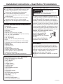
Installation Instructions - Dual Retro-Fit Installation
FLOORING
For proper installation, this product must be placed
on a level surface of hard material that is at the same
height as the rest of the flooring. This surface should
be strong enough to support a fully loaded refrigerator
or freezer, or approximately 1,200 lbs. per unit.
NOTE: Protect the finish of the flooring.
NOTE: Not recommended for installation on carpeted
flooring.
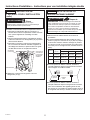
GROUNDING THE UNIT
The power cord of this appliance is equipped with a
3-prong (grounding) plug which mates with a standard
3-prong (grounding) wall receptacle to minimize the
possibility of electric shock hazard from this appliance.
Have the wall outlet and circuit checked by a qualified
electrician to make sure the outlet is properly grounded.
Where a standard 2-prong wall outlet is encountered, it
is your personal responsibility and obligation to have it
replaced with a properly grounded 3-prong wall outlet.
DO NOT, UNDER ANY CIRCUMSTANCES, CUT OR
REMOVE THE THIRD (GROUND) PRONG
FROM THE POWER CORD.
DO NOT USE AN ADAPTER
PLUG TO CONNECT THE
REFRIGERATOR TO A 2-PRONG
OUTLET.
DO NOT USE AN EXTENSION
CORD WITH THIS APPLIANCE.
REFRIGERATOR/FREEZER LOCATION
Ŷ Do not install the refrigerator/freezer where the tem-
perature will go below 55°F (13°C). It will not run
often enough to maintain proper temperatures.
Ŷ Do not install the refrigerator/freezer where
temperatures will go above 100°F (37°C). It will not
perform properly.
Ŷ Do not install the refrigerator/freezer in a location
exposed to water (rain, etc.) or direct sunlight.
Ŷ Install it on a floor strong enough to support it fully
loaded.
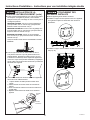
TOOLS AND MATERIALS REQUIRED
• Metal shears
• #1, #2 Phillips screwdriver
• Flathead screwdriver
• Putty knife
• Measuring tape
• Drill and 1/16”, 5/64”, 3/16”, 1/2” bits
• 5/32” concrete bit (if installing anti-tip into concrete)
• 1/4”, 3/8”, 7/16” driver/socket
• 7/16” open wrench
• T20, T30 driver/bit
• 5/64”, 1/8”, 1/4” hex driver (allen wrench)
• Level
• Water shut-off valves (optional but recommended)
• 8’ waterline (one per unit requiring water hookup)
• Masking tape
• Rubbing alcohol
• Adjustable wrench
• Center punch
• Heater Unification Kit (ZUGC)
• Stainless Steel Door Kits (if applicable)
• Custom panels for doors (if applicable)
• Handle Kits (if applicable)
• 42” (ZTKC42) or 48” (ZTKC48) Trim Retro Kit
HARDWARE SUPPLIED (per unit)
• Water Filter Bypass Plug (if equipped)
• Air filter (if equipped)
• Anti-Tip bracket
• 3 Lag screws
• 3 Tapcon screws
• 3 Toggles with bolts
• 1 Hair Pin Cotter
• 1 Retaining pin
• Panel installation templates
• 2 Door trims
• 2 Door panel brackets
• Set screws
• #6 Phillips head wood screws
• Door Bracket Cover Top
• T30 screws
• 1 Hinge limiter pin
• Center door panel bracket
• Hi-Lo screw and square washer
WARNING
Electrical Shock
Hazard. Failure to follow these instructions can
result in death, fire, or electrical shock.
La page charge ...
La page charge ...
La page charge ...
La page charge ...
La page charge ...
La page charge ...
La page charge ...
La page charge ...
La page charge ...
La page charge ...
La page charge ...
La page charge ...
La page charge ...
La page charge ...
La page charge ...
La page charge ...
La page charge ...
La page charge ...
La page charge ...
La page charge ...
La page charge ...
La page charge ...
La page charge ...
La page charge ...
La page charge ...
La page charge ...
La page charge ...
La page charge ...
La page charge ...
La page charge ...
La page charge ...
La page charge ...
La page charge ...
La page charge ...
La page charge ...
La page charge ...
La page charge ...
La page charge ...
La page charge ...
La page charge ...
La page charge ...
La page charge ...
La page charge ...
La page charge ...
La page charge ...
La page charge ...
La page charge ...
La page charge ...
La page charge ...
La page charge ...
La page charge ...
La page charge ...
La page charge ...
La page charge ...
La page charge ...
La page charge ...
La page charge ...
La page charge ...
La page charge ...
La page charge ...
La page charge ...
La page charge ...
La page charge ...
La page charge ...
La page charge ...
La page charge ...
La page charge ...
La page charge ...
La page charge ...
La page charge ...
La page charge ...
La page charge ...
La page charge ...
La page charge ...
La page charge ...
La page charge ...
La page charge ...
La page charge ...
La page charge ...
La page charge ...
La page charge ...
La page charge ...
La page charge ...
La page charge ...
La page charge ...
La page charge ...
La page charge ...
La page charge ...
La page charge ...
La page charge ...
La page charge ...
La page charge ...
La page charge ...
La page charge ...
La page charge ...
La page charge ...
-
 1
1
-
 2
2
-
 3
3
-
 4
4
-
 5
5
-
 6
6
-
 7
7
-
 8
8
-
 9
9
-
 10
10
-
 11
11
-
 12
12
-
 13
13
-
 14
14
-
 15
15
-
 16
16
-
 17
17
-
 18
18
-
 19
19
-
 20
20
-
 21
21
-
 22
22
-
 23
23
-
 24
24
-
 25
25
-
 26
26
-
 27
27
-
 28
28
-
 29
29
-
 30
30
-
 31
31
-
 32
32
-
 33
33
-
 34
34
-
 35
35
-
 36
36
-
 37
37
-
 38
38
-
 39
39
-
 40
40
-
 41
41
-
 42
42
-
 43
43
-
 44
44
-
 45
45
-
 46
46
-
 47
47
-
 48
48
-
 49
49
-
 50
50
-
 51
51
-
 52
52
-
 53
53
-
 54
54
-
 55
55
-
 56
56
-
 57
57
-
 58
58
-
 59
59
-
 60
60
-
 61
61
-
 62
62
-
 63
63
-
 64
64
-
 65
65
-
 66
66
-
 67
67
-
 68
68
-
 69
69
-
 70
70
-
 71
71
-
 72
72
-
 73
73
-
 74
74
-
 75
75
-
 76
76
-
 77
77
-
 78
78
-
 79
79
-
 80
80
-
 81
81
-
 82
82
-
 83
83
-
 84
84
-
 85
85
-
 86
86
-
 87
87
-
 88
88
-
 89
89
-
 90
90
-
 91
91
-
 92
92
-
 93
93
-
 94
94
-
 95
95
-
 96
96
-
 97
97
-
 98
98
-
 99
99
-
 100
100
-
 101
101
-
 102
102
-
 103
103
-
 104
104
-
 105
105
-
 106
106
-
 107
107
-
 108
108
-
 109
109
-
 110
110
-
 111
111
-
 112
112
-
 113
113
-
 114
114
-
 115
115
-
 116
116


GE ZIF180NPKII Guide d'installation
- Catégorie
- Frigos
- Taper
- Guide d'installation
dans d''autres langues
- English: GE ZIF180NPKII Installation guide
Documents connexes
Autres documents
-
ROOMS TO GO 42923486 Assembly Instructions
-
Monogram ZIF301NPNII Guide d'installation
-
Monogram ZIR301NBRII Guide d'installation
-
Monogram ZKR36R Manuel utilisateur
-
Frigidaire FRT18S6JS Le manuel du propriétaire
-
Signature Kitchen Suite SKSCW241RP Guide d'installation
-
KitchenAid KBBX104EPA Guide d'installation
-
Baumer Adaptor plate for clamping flange for modification into square flange (Z 119.001) Fiche technique
-
 GE Monogram ZIRS360NBRH Guide d'installation
-
Liebherr CS1400L Guide d'installation
