
Mounting Instructions | Montageanleitung |
Notice de montage
English Deutsch Français
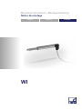
WI

Hottinger Baldwin Messtechnik GmbH
Im Tiefen See 45
D-64293 Darmstadt
Tel. +49 6151 803-0
Fax +49 6151 803-9100
www.hbm.com
Mat.: 7-2001.1243
DVS: A01028_05_Y00_01 HBM: public
09.2019
E Hottinger Baldwin Messtechnik GmbH.
Subject to modifications.
All product descriptions are for general information only.
They are not to be understood as a guarantee of quality or
durability.
Änderungen vorbehalten.
Alle Angaben beschreiben unsere Produkte in allgemeiner
Form. Sie stellen keine Beschaffenheits- oder Haltbarkeits
garantie dar.
Sous réserve de modifications.
Les caractéristiques indiquées ne décrivent nos produits
que sous une forme générale. Elles n'impliquent aucune
garantie de qualité ou de durabilité.

Mounting Instructions | Montageanleitung |
Notice de montage
English Deutsch Français
WI

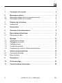
2 A01028_05_Y00_01 HBM: public WI
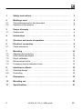
English
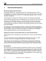
1 Safety instructions 3........................................
2 Markings used 5............................................
2.1 The markings used in this document 5..........................
2.2 Symbols on the product 5.....................................
3 Scope of supply 6..........................................
3.1 Accessories 6...............................................
4 Introduction 6..............................................
5 Structure and mode of operation 7...........................
6 Electrical connection 8......................................
6.1 Cable extensions 9..........................................
7 Mounting 10.................................................
7.1 Adjusting the centering 11.....................................
7.2 Initial stroke adjustment 12.....................................
7.3 Direct calibration 13...........................................
7.4 Measurement circle 13........................................
7.5 Frequency and acceleration limits 14............................
8 Interference effects 15.......................................
8.1 Shielding design 15...........................................
8.2 Grounding 15................................................
9 Dimensions 16..............................................
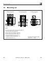
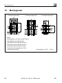
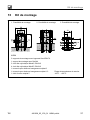
10 Mounting set 20.............................................
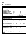
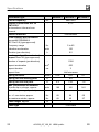
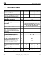
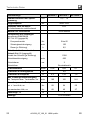
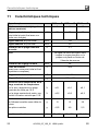
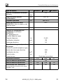
11 Specifications 21............................................

Safety instructions
WI A01028_05_Y00_01 HBM: public 3
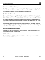
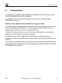
1 Safety instructions
Use in accordance with the regulations
Displacement transducers of the WI series are intended for displacement
measurements such as in test rigs, for installation in measurement stands and
all types of measuring apparatus for testing and checking workpieces and for
checking processes in manufacturing or the construction industry.
Use for any additional purpose shall be deemed to be not in accordance with
the regulations.
In the interests of safety, the transducer should only be operated as described
in the Mounting Instructions. It is also essential to observe the appropriate legal
and safety regulations for the application concerned during use. The same
applies to the use of accessories.
The transducer is not a safety element within the meaning of its use as
intended. Proper and safe operation of this transducer requires proper
transportation, correct storage, assembly and mounting and careful operation
and maintenance.
General dangers of failing to follow the safety instructions
The WI displacement transducer corresponds to the state of the art and is
fail‐safe.
The transducers can give rise to residual dangers if they are inappropriately
installed and operated by untrained personnel.
Everyone involved with the installation, commissioning, maintenance or repair
of a displacement transducer must have read and understood the mounting
instructions and in particular the technical safety instructions.
Remaining dangers
The scope of supply and performance of the transducer covers only a small
area of displacement measurement technique. In addition, equipment planners,
installers and operators should plan, implement and respond to the safety
engineering considerations of displacement measurement technique in such a
way as to minimize remaining dangers. Prevailing regulations must be

Safety instructions
4 A01028_05_Y00_01 HBM: public WI
complied with at all times. There must be reference to the remaining dangers
connected with displacement measurement technique.
Conversions and modifications
The transducer must not be modified from the design or safety engineering
point of view except with our express agreement. Any modification shall
exclude all liability on our part for any damage resulting therefrom.
Qualified personnel
This instrument is only to be installed by qualified personnel strictly in
accordance with the technical data and with the safety rules and regulations
which follow. It is also essential to observe the appropriate legal and safety
regulations for the application concerned. The same applies to the use of
accessories.
Qualified personnel means persons entrusted with the installation, fitting, com
missioning and operation of the product who possess the appropriate qualifica
tions for their function.
Conditions on site
Protect the transducer from damp and weather influences such as rain, snow,
etc.
Accident prevention
The relevant accident prevention regulations of the trade safety associations
must be taken into account.

Markings used
WI A01028_05_Y00_01 HBM: public 5
2 Markings used
2.1 The markings used in this document
Important instructions for your safety are specifically identified. It is essential to
follow these instructions in order to prevent accidents and damage to property.
Symbol Significance
Notice
This marking draws your attention to a situation in
which failure to comply with safety requirements can
lead to damage to property.
Emphasis
See….
Italics are used to emphasize and highlight text and
references to other chapters and external docu
ments.
2.2 Symbols on the product
CE mark
The CE mark enables the manufacturer to guarantee that
the product complies with the requirements of the rele
vant EC directives (the declaration of conformity is avail
able at http://www.hbm.com/HBMdoc
).

Scope of supply
6 A01028_05_Y00_01 HBM: public WI
3 Scope of supply
S Displacement transducer with fitted cable
S Operating Manual
3.1 Accessories
Mounting kit:
8 mm mounting block and tool, order no.: 1-WZB8
4 Introduction
The WI series of inductive miniature displacement transducers is designed to
be particularly compact. The transducers feature a clamping shaft of only 8 mm
and an extremely short total length.
Interrelationship between nominal displacement and total length
The transducer with the nominal displacement of 2 mm is only 66 mm long, for
the nominal displacement of 5 mm the length is 79 mm and for a nominal
displacement of 10 mm only 95 mm.
For reciprocating measurement objects or if no other means exist, the probe
versions are used.
The probe pin with the plunger is easily installed in a guideway, being not only
free from backlash and non‐wearing, but also spring‐loaded to keep it pressed
against the measurement object.
WI inductive miniature displacement probes are therefore suitable as precision
measuring probes in measurement stands and measuring apparatus.

Structure and mode of operation
WI A01028_05_Y00_01 HBM: public 7
5 Structure and mode of operation
The transducers consist of a ferromagnetic core and a coil tube, on which are
located two measuring coils arranged in tandem, together forming an inductive
half bridge.
The ferromagnetic core is mounted on a non‐magnetic rod and located in the
center of the coil system. Axial displacements of the core lead to an opposite
change in the impedance of the measuring coils.
A ferrite tube acts as an enclosure surrounding the coil system and at the same
time forms the magnetic shielding. Under a plastic molding are resistors with
which to adjust the sensitivity of the transducers and which also form the
extension to the full bridge.
In the probe versions there are guideways made of antifriction metal on the
core rod, giving access to the coil tube. A spiral spring pushes the probe pin
forward against the measurement object. On the tip is an measurement insert
according to DIN 878 with a threaded pin M2.5 and a 1/8” carbide ball.
Notice
The measurement insert is locked using a medium‐strength threadlocker.

Electrical connection
8 A01028_05_Y00_01 HBM: public WI
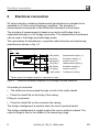
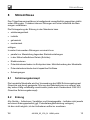
6 Electrical connection
WI series inductive miniature displacement transducers are intended to be
operated on 4.8 kHz carrier‐frequency amplifiers. The principle of
measurement corresponds to the differential inductance coil principle.
The principle of measurement is based on an active half bridge that is
expanded internally to a full bridge connection. The displacement transducers
can be used in full‐bridge and half‐bridge mode.
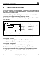
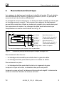
The connections for transducers, a possible cable extension and measuring
amplifiers are shown in Fig. 6.1.
WH (white) Measurement signal ())
BU (blue) Excitation voltage (+)
RD (red)
1)
Measurement signal (-)
GY (gray) Sensor circuit (-)
GN (green) Sensor circuit (+)
Cable shield Transducer housing
BK (black) Excitation voltage (-)
1)
When used in full bridge connection, otherwise not used
0 )
Fig. 6.1 Electrical schematic diagram of a full bridge, six‐wire extension
Connecting to terminals:
S The shield can be accessed through a notch in the cable sheath
S Place the shield flat on the body of the casing.
Fitting to a connector:
S Place the shield flat on the connector the casing.
The bridge misalignment is positive when the core is pushed inward.
The bridge misalignment is negative when the core is pushed outward. The
output voltage is zero in the middle of the measuring range.

Electrical connection
WI A01028_05_Y00_01 HBM: public 9
In order to keep the size down, the transducer is not fitted with integrated
sense leads for operating in a six‐wire circuit.
When operating with a six‐wire measuring amplifier therefore, the feedback
inputs must be connected to the appropriate supply leads (see Fig. 6.1).
The effect of the fitted four‐wire cable is taken into account during factory
calibration.
6.1 Cable extensions
When operating with a six‐wire measuring amplifier the cable can be extended
without any ill effects (maximum 200 meters).
The prerequisite for this is the use of a high‐grade, low‐capacitance
measurement cable. The supplementary sense leads (HBM colors gray and
green) then assess the voltage at the transducer connection and feed it back to
the six‐wire measuring amplifier. This regulates the voltage so that it reaches
the transducer loss‐free.

Mounting
10 A01028_05_Y00_01 HBM: public WI
7 Mounting
The transducer has a clamping shank Ø8
+0.05
. It can be clamped along the
entire length of the metallic enclosure tube.
It must be clamped so that the enclosure tube is not distorted by clamping
forces. The fitted connection cable must not be subjected to loads by pulling or
vibration.
The contact force of the probe is dependent on the installation site.
In the event of loading due to acceleration, e.g. due to vibrations, oscillations
etc., please refer to chapter 7.5 ”Frequency and acceleration limits”, page 14.
Notice
Never apply force to the plastic potting compound during mounting. No tor
sional load must be applied to the plastic connection or the metal housing.

Mounting
WI A01028_05_Y00_01 HBM: public 11
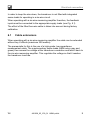
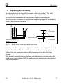
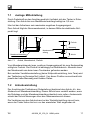
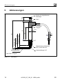
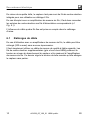
7.1 Adjusting the centering
Spring pressure on the stop puts the probe in the rest position. The initial
stroke as far as the start of the measuring range is around 0.5 mm.
At this point the transducer has its maximum negative output signal.
The initial stroke is followed by the nominal measuring range, in the middle of
which is the electrical zero point.
Initial stroke approx. 0.5mm
Measuring range
Free stroke
Start of measuring
range
Initial stroke
Displacement
Free stroke
Start of measuring
range
Fig. 7.1 Initial stroke, measuring range, free stroke
From the end of the measuring range (max. positive output signal) to the end
stop is a free stroke. The free stroke depends on the measuring range.
Alternatively the measuring range can be found as in the case of a free
plunger:
With a neutral amplifier setting (no zero point adjustment, no tare) adjust the
probe pin to a zero display. Half the measurement displacement lies on either
side of this position.

Mounting
12 A01028_05_Y00_01 HBM: public WI
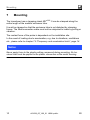
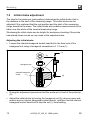
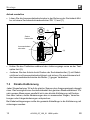
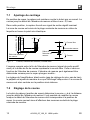
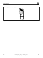
7.2 Initial stroke adjustment
The stop for the probe pin (rest position) determines the initial stroke, that is,
the distance to the start of the measuring range. This initial stroke can be
adjusted if it is preferred that the rest position and the start of the measuring
range should be the same. The initial stroke also enables measurements to be
taken over the whole of the nominal measuring range.
Shortening the initial stroke can be helpful for workpiece checking if the probe
has already been moved up very close to the expected value.
Adjusting the initial stroke
S Loosen the internal hexagonal socket head bolt in the bore hole of the
hexagonal nut using a hexagonal screwdriver a.f. 1.3 mm (1)
Hexagonal nut
Internal hexagonal
screw
(1)
(2)
(3)
S During the adjustment procedure hold the probe pin in front of the probe tip
(2).
S Adjust the initial stroke by turning the hexagonal nut (3) using an open‐end
wrench and an internal hexagonal socket wrench, and then use the internal
hexagonal socket head bolt to stop the nut (1) from twisting.

Mounting
WI A01028_05_Y00_01 HBM: public 13
7.3 Direct calibration
Adjust each WI displacement transducer to the same span of the output signal.
This enables interchangeability when the measuring amplifiers are the same.
For very precise measurements, we recommend direct calibration using gage
blocks or templates with dimensions corresponding to the displacement,
movement or change in length that you wish to measure.
When there are cable extensions, the entire cable length should be included in
the calibration procedure.
More notes on calibration can be found in the appropriate operating manual for
the selected amplifier.
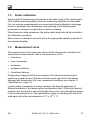
7.4 Measurement circle
The measurement circle means the sum of all the dimensions included in the
displacement measurement, that is, the dimensions of the
S transducer
S core or probe pin
S workpiece
S workpiece fastener
S transducer fastener
Temperature changes shift the zero signal of the inductive measurement
system by a small amount. Also the nominal output span of the transducer
changes with temperature (for max. temperature variations see chapter 11
“Specifications”, page 21).
In most cases a temperature change results in the thermal expansion of
different materials in the measurement configuration itself. When high levels of
precision are required it is essential to take account of every thermal expansion
in the measurement circle. The specifications apply to clamping with the aid of
steel parts with a thermal expansion of 11 x 10
-6
/ °C.

Mounting
14 A01028_05_Y00_01 HBM: public WI
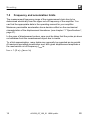
7.5 Frequency and acceleration limits
The measurement frequency range of the measurement chain has to be
determined electrically from the upper cut‐off frequency of the amplifier. You
can find the appropriate data in the operating manual for your amplifier.
Maximum permissible acceleration has a decisive effect on the mechanical
characteristics of the displacement transducer (see chapter 11 “Specifications”,
page 21).
In the case of displacement probes, care must be taken that the probe pin does
not withdraw from the measurement object due to inertia.
To a first approximation, many tasks may generally be regarded as sinusoidal.
At maximum permitted acceleration a
max
with given displacement amplitude s
the mechanical cut‐off frequency f
max
is:
f
max
= 1 /(2 π) Ǩ(a
max
/ s)

Interference effects
WI A01028_05_Y00_01 HBM: public 15
8 Interference effects
Carrier frequency transmission is highly insensitive to electrical interference.
Even so, high‐intensity interference can falsify measurements.
Interference can be injected into a measuring circuit from a source which is:
S electromagnetic,
S inductive,
S galvanic,
S mechanical.
Interference is most commonly caused by:
S high‐power transmission lines running parallel to the measurement circuit
S nearby relays (contactors)
S electric motors
S potential differences in the grounding system or polyphase grounding of the
measurement chain
S potential differences caused by capacitive influences
S vibration
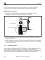
8.1 Shielding design
Using HBM's Greenline shielding design ensures that the entire measurement
chain is completely enclosed in a Faraday cage, due to the special way the
cable shield is arranged (see also reprint G36.35.0, Greenline shielding
design).
8.2 Grounding
All devices - transducers, amplifiers and display devices - are located on
a ground potential (if necessary wire to a potential equalization line).
If this is not possible, the transducer should be fitted ground‐isolated.

Dimensions
16 A01028_05_Y00_01 HBM: public WI
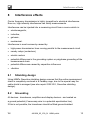
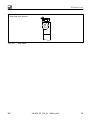
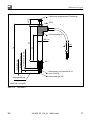
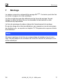
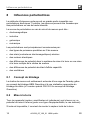
9 Dimensions
Measuring range 2 mm
Initial stroke 0.5 mm
Free stroke approx. 5 mm
66
ø3
43
29
Position when probe pin
driven in
a.f. 5
Plastic molding
Measurement insert
threaded M 2.5 to DIN 878
Carbide ball 1/8”
Starting position
ø5.7
to DIN 7168 coarse
Ø8
+0.05
approx.
12
Fig. 9.1 WI/2mm-T

Dimensions
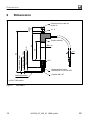
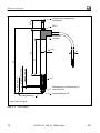
WI A01028_05_Y00_01 HBM: public 17
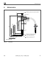
Initial stroke 0.5 mm
Measuring range 5 mm
Free stroke approx. 2.5 mm
79
ø3
56
42
Position when probe pin
driven in
a.f. 5
Measurement insert threaded
M 2.5 to DIN 878
Carbide ball 1/8”
Starting position
Plastic molding
ø5.7
to DIN 7168 coarse
Ø8
+0.05
approx.
12
Fig. 9.2 WI/5mm-T

Dimensions
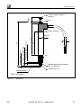
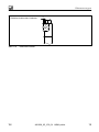
18 A01028_05_Y00_01 HBM: public WI
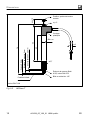
Initial stroke 0.5 mm
Measuring range 10 mm
Free stroke approx. 1.5 mm
95
ø3
65
52
Position when probe pin driven in
a.f. 5
Measurement insert threaded
M 2.5 to DIN 878
Carbide ball 1/8”
Starting position
Plastic
molding
ø5.7
to DIN 7168 coarse
Ø8
+0.05
approx.
16
Fig. 9.3 WI/10mm-T
La page est en cours de chargement...
La page est en cours de chargement...
La page est en cours de chargement...
La page est en cours de chargement...
La page est en cours de chargement...
La page est en cours de chargement...
La page est en cours de chargement...
La page est en cours de chargement...
La page est en cours de chargement...
La page est en cours de chargement...
La page est en cours de chargement...
La page est en cours de chargement...
La page est en cours de chargement...
La page est en cours de chargement...
La page est en cours de chargement...
La page est en cours de chargement...
La page est en cours de chargement...
La page est en cours de chargement...
La page est en cours de chargement...
La page est en cours de chargement...
La page est en cours de chargement...
La page est en cours de chargement...
La page est en cours de chargement...
La page est en cours de chargement...
La page est en cours de chargement...
La page est en cours de chargement...
La page est en cours de chargement...
La page est en cours de chargement...
La page est en cours de chargement...
La page est en cours de chargement...
La page est en cours de chargement...
La page est en cours de chargement...
La page est en cours de chargement...
La page est en cours de chargement...
La page est en cours de chargement...
La page est en cours de chargement...
La page est en cours de chargement...
La page est en cours de chargement...
La page est en cours de chargement...
La page est en cours de chargement...
La page est en cours de chargement...
La page est en cours de chargement...
La page est en cours de chargement...
La page est en cours de chargement...
La page est en cours de chargement...
La page est en cours de chargement...
La page est en cours de chargement...
La page est en cours de chargement...
La page est en cours de chargement...
La page est en cours de chargement...
La page est en cours de chargement...
La page est en cours de chargement...
-
 1
1
-
 2
2
-
 3
3
-
 4
4
-
 5
5
-
 6
6
-
 7
7
-
 8
8
-
 9
9
-
 10
10
-
 11
11
-
 12
12
-
 13
13
-
 14
14
-
 15
15
-
 16
16
-
 17
17
-
 18
18
-
 19
19
-
 20
20
-
 21
21
-
 22
22
-
 23
23
-
 24
24
-
 25
25
-
 26
26
-
 27
27
-
 28
28
-
 29
29
-
 30
30
-
 31
31
-
 32
32
-
 33
33
-
 34
34
-
 35
35
-
 36
36
-
 37
37
-
 38
38
-
 39
39
-
 40
40
-
 41
41
-
 42
42
-
 43
43
-
 44
44
-
 45
45
-
 46
46
-
 47
47
-
 48
48
-
 49
49
-
 50
50
-
 51
51
-
 52
52
-
 53
53
-
 54
54
-
 55
55
-
 56
56
-
 57
57
-
 58
58
-
 59
59
-
 60
60
-
 61
61
-
 62
62
-
 63
63
-
 64
64
-
 65
65
-
 66
66
-
 67
67
-
 68
68
-
 69
69
-
 70
70
-
 71
71
-
 72
72


HBM WI Series Mounting instructions
- Catégorie
- Mesure
- Taper
- Mounting instructions
dans d''autres langues
- English: HBM WI Series
- Deutsch: HBM WI Series
Documents connexes
Autres documents
-
Sony Ericsson HBM-30 Manuel utilisateur
-
MS Schippers 0809889 Manuel utilisateur
-
Omega EP310S Le manuel du propriétaire
-
-
Xilinx Alveo U50 Manuel utilisateur
-
Topcom HBM Sensor Watch 2002 Manuel utilisateur
-
-
Wolf Garten HBM 40 B Manuel utilisateur
-
-
BLACK+DECKER LEDUC9-3CK Mode d'emploi