Tweco Robotics QRC™-2000 Nozzle Cleaning Station Guide d'installation
- Taper
- Guide d'installation

50
60
Hz
1
PHASE
GTAW
SMAW
INVERTER
CC
DC
115
V
230
V
NOZZLE CLEANING
STATION
Installation and Operation
Guide
English
Français
Español
QRC
TM
-2000
Revision No: A Issue Date: November 17, 2008 Manual No: SM-QRC-2000

50
60
Hz
1
PHASE
GTAW
SMAW
INVERTER
CC
DC
115
V
230
V
Congratulations on your new Tweco
®
Robotics product. We are proud
to have you as our customer and will strive to provide you with the
best service and reliability in the industry. This product is backed by
our extensive warranty and world-wide service network. To locate your
nearest distributor or service agency, please contact a representative at
the address and phone number in your area listed on the inside back
cover of this manual, or visit us on the web at www.tweco.com.
This Operating Manual has been designed to instruct you on the correct
use and operation of your Tweco
®
Robotics product. Your satisfaction
with this product and its safe operation is our ultimate concern.
Therefore, please take the time to read the entire manual, especially the
Safety Precautions. They will help you to avoid potential hazards that
may exist when working with this product.
YOU ARE IN GOOD COMPANY!
The Brand of Choice for Contractors and Fabricators Worldwide.
Tweco
®
Robotics is a Global Brand of Arc Welding Products for
Thermadyne Industries Inc. We manufacture and supply to major
welding industry sectors worldwide including; Manufacturing,
Construction, Mining, Automotive, Aerospace, Engineering, Rural and
DIY/Hobbyist.
We distinguish ourselves from our competition through market-leading,
dependable products that have stood the test of time. We pride ourselves
on technical innovation, competitive prices, excellent delivery, superior
customer service and technical support, together with excellence in
sales and marketing expertise.
Above all, we are committed to develop technologically advanced
products to achieve a safer working environment within the welding
industry.
WE APPRECIATE YOUR BUSINESS!

WARNING
READ AND UNDERSTAND THIS ENTIRE MANUAL AND YOUR EMPLOYER’S SAFETY PRACTICES BEFORE INSTALLING,
OPERATING, OR SERVICING THE EQUIPMENT.
WHILE THE INFORMATION CONTAINED IN THIS MANUAL REPRESENTS THE MANUFACTURER’S BEST JUDGMENT, THE
MANUFACTURER ASSUMES NO LIABILITY FOR ITS USE.
Nozzle Cleaning Station
Installation and Operation Guide
Instruction Manual Number SM-QRC-2000
Published by:
Tweco
®
Products Inc.
2800 Airport Road
Denton, TX 76208
(940) 566-2000
www.tweco.com
Copyright © 2008 by
Thermadyne Industries Inc.
®
All rights reserved.
Reproduction of this work, in whole or in part, without written permission of the publisher is prohibited.
The publisher does not assume and hereby disclaims any liability to any party for any loss or damage caused by any
error or omission in this Manual, whether such error results from negligence, accident, or any other cause.
Publication Date: November 17, 2008
Record the following information for Warranty purposes:
Where Purchased: ________________________
Purchase Date: ________________________
Equipment Serial #: ________________________
i

nozzle cleaning station
ii
SM-QRC-2000
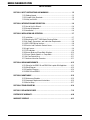
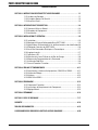
Table of Contents
SECTION 1: SAFETY INSTRUCTIONS AND WARNINGS .......................................... 1-3
1.01 Welding Hazards .......................................................................................1-3
1.02 Principal Safety Standards ........................................................................1-5
1.03 Safety and Health ......................................................................................1-5
SECTION 2: INTRODUCTION AND DESCRIPTION ................................................. 2-6
2.01 How to Use this Manual ............................................................................2-6
2.02 Receipt of Equipment ................................................................................2-6
2.03 Introduction ..............................................................................................2-6
SECTION 3: INSTALLATION AND OPERATION ..................................................... 3-7
3.01 Installation ................................................................................................3-7
3.02 Mounting the QRC
TM
-2000 Nozzle Cleaning Station ..................................3-7
3.03 Air Supply, Connections, and Lubrication Requirements ..........................3-8
3.04 QRC
TM
-2000 Wiring Interface ....................................................................3-8
3.05 Electrical and Pneumatic Controls Access ................................................3-9
3.06 Logic Inverse ............................................................................................3-9
3.07 LED Indicators ..........................................................................................3-9
3.08 Reamer Blade and Clamp Block Selection ...............................................3-10
3.09 Tweco
®
Robotic Nozzles vs. Clamp Block ...............................................3-11
3.10 Air Flow Control Valve .............................................................................3-11
3.11 Nozzle and Insertion Parameter ..............................................................3-11
SECTION 4: WIRING AND PNEUMATIC ............................................................
4-13
4.01 Wiring for the QRM-100 and QRM-3 Anti-spatter Mist Applicator .........4-13
4.02 Wiring Diagram .......................................................................................4-13
4.03 Pneumatic Diagram .................................................................................4-14
4.03 QRM-100 and QRM-3 .............................................................................4-14
SECTION 5: MAINTENANCE .........................................................................
5-15
5.01 Maintenance Schedule ............................................................................5-15
5.02 Component Replacement Instructions ....................................................5-15
5.03 Manual Setup ..........................................................................................5-17
SECTION 6: TROUBLESHOOTING ..................................................................
6-18
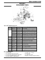
SECTION 7: REPLACEMENT PARTS ................................................................
7-19
STATEMENT OF WARRANTY ........................................................................
8-20
WARRANTY SCHEDULE .............................................................................
8-21

nozzle cleaning station
1-3
SM-QRC-2000
SAFETY INSTRUCTIONS AND WARNINGS
SECTION 1:
SAFETY INSTRUCTIONS AND WARNINGS
WARNING
SERIOUS INJURY OR DEATH MAY RESULT IF WELDING AND CUTTING EQUIPMENT IS NOT PROPERLY INSTALLED,
USED AND MAINTAINED. MISUSE OF THIS EQUIPMENT AND OTHER UNSAFE PRACTICES CAN BE HAZARDOUS. THE
OPERATOR, SUPERVISOR, AND HELPER MUST READ AND UNDERSTAND THE FOLLOWING SAFETY WARNINGS AND
INSTRUCTIONS BEFORE INSTALLING OR USING ANY WELDING OR CUTTING EQUIPMENT.
THE WELDING AND CUTTING PROCESS IS USED IN MANY POTENTIALLY DANGEROUS ENVIRONMENTS SUCH
AS ELEVATED HEIGHTS, AREAS OF LIMITED VENTILATION, CLOSE QUARTERS, AROUND WATER, IN HOSTILE
ENVIRONMENTS, ETC., AND IT IS IMPORTANT THAT THE OPERATOR(S) ARE AWARE OF THE DANGERS ASSOCIATED
WITH WORKING IN THESE TYPES OF CONDITIONS. BE CERTAIN THAT THE OPERATOR(S) ARE TRAINED IN
SAFE PRACTICES FOR ENVIRONMENTS IN WHICH THEY ARE EXPECTED TO WORK AND UNDER COMPETENT
SUPERVISION.
IT IS ESSENTIAL THAT THE OPERATOR, SUPERVISOR AND ALL OTHER PERSONNEL IN THE WORK AREA ARE AWARE
OF THE DANGERS OF THE WELDING OR CUTTING PROCESS. TRAINING AND PROPER SUPERVISION ARE IMPORTANT
FOR A SAFE WORK PLACE. KEEP THESE INSTRUCTIONS FOR FUTURE USE. ADDITIONAL RECOMMENDED SAFETY
AND OPERATING INFORMATION IS REFERENCED IN EACH SECTION.
5. All ground connections must be checked periodically
to determine that they are mechanically strong and
electrically adequate for the required current.
6. When engaged in alternating current, welding, or
cutting under wet conditions or warm surroundings
where perspiration is a factor, the use of reliable
automatic controls for reducing the no-load voltage
is recommended to reduce shock hazard.
7. When the welding or cutting process requires values of
open circuit voltages in alternating current machines
higher than 80 volts, and direct current machines
higher than 100 volts, means must be provided to
prevent the operator from making accidental contact
with the high voltage by adequate insulation or other
means.
8. When welding is to be suspended for any substantial
length of time, such as during lunch or overnight,
all electrodes should be removed from the electrode
holder and the electrode holder carefully located so
that accidental contact cannot occur.
9. The holder must be disconnected from the power
source when not in use.
10.
Never immerse Mig-Guns, electrode holders, tig
torches, plasma torches, or electrodes in water.
WARNING
SMOKE, FUMES, AND GASES CAN BE DANGEROUS
TO YOUR HEALTH.
1.01 Welding Hazards
WARNING
ELECTRIC SHOCK CAN CAUSE INJURY OR DEATH.
INSTALL AND MAINTAIN EQUIPMENT IN ACCORDANCE
WITH THE NATIONAL ELECTRICAL CODE (NFPA 70)
AND LOCAL CODES. DO NOT SERVICE OR REPAIR
EQUIPMENT WITH POWER ON. DO NOT OPERATE
EQUIPMENT WITH PROTECTIVE INSULATORS
OR COVERS REMOVED. SERVICE OR REPAIR TO
EQUIPMENT MUST BE DONE BY A QUALIFIED REPAIR
TECHNICIAN, OR TRAINED PERSONNEL ONLY.
1. Do not touch live electrical parts.
2.
Do not touch an electrode with bare skin and electrical
ground at the same time.
3. Always keep welding gloves dry and in good
condition.
NOTE
Aluminized protective clothing can become
part of the electrical path.
4. Keep oxygen cylinders, chains, wire ropes, cranes,
hoists, and elevators away from any part of the
electrical path.

nozzle cleaning station
1-4
SM-QRC-2000
SAFETY INSTRUCTIONS AND WARNINGS
21. Flammable hair preparations should not be used when
welding or cutting. Wear ear plugs to protect ears from
sparks.
22. Where the work area permits, the operator should be
enclosed in an individual booth painted with a finish of
low reflectivity such as zinc oxide. This is an important
factor for absorbing ultraviolet radiations, and lamp black.
The operator should be enclosed with non-combustible
screens similarly painted.
WARNING
WELDING SPARKS CAN CAUSE FIRES AND
EXPLOSIONS.
23. Causes of fire and explosion are: combustibles reached by
the arc, flame, flying sparks, hot slag, or heated material.
Remove combustibles from the work area and/or provide
a fire watch.
24
. Avoid oily or greasy clothing as sparks may ignite them. Have
a fire extinguisher nearby, and know how to use it.
25.
Be alert to the danger of conduction or radiation. For
example, if welding or cutting is to be done on a metal
wall, partition, ceiling, or roof, precautions must be taken
to prevent ignition of combustibles on the other side.
26. Do not w
eld or cut containers that have held combustibles.
All hollow spaces, cavities and containers should be vented
prior to welding or cutting to permit the escape of air or
gases. Purging with inert gas is recommended.
27.
Never use oxygen in a welding torch. Use only inert
gases or inert gas mixes as required by the process. Use
of combustible compressed gases can cause explosions
resulting in personal injury or death. Arcing against any
compressed gas cylinder can cause cylinder damage or
explosion.
WARNING
NOISE CAN DAMAGE HEARING.
28. Noise from the air carbon-arc process can damage
your hearing. Wear protective hearing devices to ensure
protection when noise levels exceed OSHA standards.
Adequate hearing protection devices must be worn by
operators and surrounding personnel to ensure personal
protection against noise.
11. Keep smoke, fumes, and gases from the breathing area.
12. Fumes from the welding or cutting process are of various
types and strengths, depending on the kind of base metal
being worked on. To ensure your safety, do not breathe
these fumes.
13. Ventilation must be adequate to remove smoke, fumes,
and gases during the operation to protect operators and
other personnel in the area.
14. Vapors of chlorinated solvents can form the toxic gas
“Phosgene” when exposed to ultraviolet radiation from
an electric arc. All solvents, degreasers, and potential
sources of these vapors must be removed from the work
area.
15. Fumes produced by welding or cutting, particularly in
confined places, can cause discomfort and physical harm
if inhaled over an extended period of time.
16. Provide adequate ventilation in the welding or cutting area.
Use air-supplied respirators if ventilation is not adequate
to remove all fumes and gases. Never ventilate with
oxygen. Oxygen supports and vigorously accelerates
fire.
WARNING
ARC RAYS, HOT SLAG, AND SPARKS CAN INJURE
EYES AND BURN SKIN .
17. The welding and cutting processes produces extreme
localized heat and strong ultraviolet rays.
18. Never attempt to weld or cut without a welding helmet
with the proper lens. Ensure that the lens complies with
federal guidelines. A number 12 to 14 shade filter lens
provides the best protection against arc radiation. When
in a confined area, prevent the reflected arc rays from
entering around the helmet.
19. Ensure all personnel in the work area are protected from
arc rays and sparks. Approved shielding curtains and
appropriate goggles should be used to provide protection
to staff in the surrounding area and operators of nearby
equipment.
20. Unprotected skin should also be covered from arc rays,
heat and molten metal. Always wear protective gloves and
clothing that does not allow skin to become exposed. All
pockets should be closed and cuffs sewn shut. Leather
aprons, sleeves, leggings, etc., should be worn for out-of-
position welding and cutting or for heavy operations using
large electrodes. High top work shoes provide adequate
protection from foot burns. For added protection use
leather spats.

nozzle cleaning station
1-5
SM-QRC-2000
SAFETY INSTRUCTIONS AND WARNINGS
1.02 Principal Safety Standards
1.03 Safety and Health
NOTE
Be sure to read and fully comprehend the safety
instuctions and warnings contained within
section 1 of this manual before performing
any welding or cutting operations.
WARNING
SERIOUS INJURY OR DEATH MAY RESULT IF
WELDING AND CUTTING EQUIPMENT IS NOT
PROPERLY INSTALLED, USED, AND MAINTAINED.
MISUSE OF THIS EQUIPMENT, OR OTHER UNSAFE
PRACTICES, CAN BE HAZARDOUS.
Electric shock can cause injury or death.
Smoke, fumes, and gases can be dangerous to your
health.
Arc rays, hot slag, and sparks can injure or burn
unprotected eyes and skin.
Welding sparks can cause fires and explosions.
Excessive noise can damage your hearing.
•
•
•
•
•
SAFETY AND OPERATING REFERENCES
1. Code of Federal Regulations. (OSHA)
Section 29 Part 1910.95, 132, 133, 134, 139, 251, 252, 253, 254 and 1000.
U.S. Government Printing Office, Washington, DC. 20402.
2. ANSl Z49.1 “Safety In Welding and Cutting”.
3. ANSI Z87.1 “Practice for Occupational and Educational Eye and Face Protection”.
4. ANSl Z88.2 “Standard Practice for Respiratory Protection”.
American National Standards Institute, 1430 Broadway, New York, NY. 10018.
5. AWS F4.1 “Recommended Safe Practices for Welding and Cutting Containers”.
6. AWS C5.3 “Recommended Practices for Air Carbon-Arc Gouging and Cutting”.
The American Welding Society, 550 NW Lejeune RD., P.O.Box 351040, Miami FL. 33135.
7. NFPA 51B “Fire Prevention in Cutting and Welding Processes”.
8. NFPA-7 “National Electrical Code”.
National Fire Protection Association, Battery Park, Quincy, MA. 02269.
9. CSA W117.2, “Safety in Welding, Cutting and Allied Processes”.
Canadian Standards Association, 178 Rexdale Blvd., Rexdale, Ontario, Canada M9W 1R3.
Warning
This producT conTains chemicals, including
lead, or oTherWise produces chemicals knoWn
To The sTaTe of california To cause cancer,
birTh defecTs and oTher reproducTive harm.
W a s h h a n d s a f t e r h a n d l i n g .
(california healTh & safeTy code § 25249.5 eT
seq.)

nozzle cleaning station
2-6
SM-QRC-2000
INTRODUCTION AND DESCRIPTION
2.01 How to Use this Manual
To ensure safe operation, read the entire manual, including
the chapters on safety instructions and warnings.
Throughout this manual, the words WARNING, CAUTION,
and NOTE may appear. Pay particular attention to the
information provided under these headings. These special
anNotetions are easily recognized as follows:
WARNING
A WARNING GIVES INFORMATION REGARDING
POSSIBLE PERSONAL INJURY.
CAUTION
A CAUTION refers to possible equipment
damage.
NOTE
A NOTE offers helpful information concerning
certain operating procedures.
2.02 Receipt of Equipment
When you receive the equipment, check it against the
invoice to make sure it is complete and inspect the
equipment for possible damage due to shipping. If there is
any damage, notify the carrier immediately to file a claim.
Furnish complete information concerning damage claims
or shipping errors to the location in your area listed in the
inside back cover of this manual. Include a full description
of the parts in error.
If you want additional or replacement copies of this CD,
please contact Tweco
®
Robotics at the address and phone
number in your area listed on the inside back cover of this
manual. Include the Manual number (from page i) and
CD part number: CDROBOTICS.
SECTION 2:
INTRODUCTION AND DESCRIPTION
2.03 Introduction
Before installing or operating the QRC
TM
-2000 Nozzle
Cleaning Station, please read and understand all safety
precautions included with this product and instructions
listed in this manual. Failure to follow all instructions and
safety warnings can result in personal injury or equipment
damage.
The Tweco
®
Robotics QRC
TM
-2000 Nozzle Cleaning Station
was designed to provide the user with high quality nozzle/
tip cleaning that fits well in a robotic work cell. This durable
product is a proven performer in the rigorous environment
associated with a continuous operating robotic station.

nozzle cleaning station
3-7
SM-QRC-2000
INSTALLATION AND OPERATION
SECTION 3:
INSTALLATION AND OPERATION
3.01 Installation
The Tweco
®
Robotics QRC
TM
-2000 Nozzle Cleaning Station
is easy to install. The following are instructions to aid in
mounting and making all necessary connections to your
cleaning station. If you have any questions concerning
these instructions, contact Tweco
®
Robotics Technical
Services for further assistance.
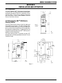
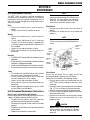
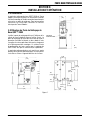
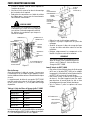
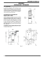
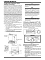
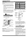
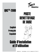
3.02 Mounting the QRC
TM
-2000 Nozzle
Cleaning Station
Install the nozzle cleaning station inside the robot work
cell to make it easy to access. The nozzle cleaning station
should be mounted to allow easy access to the robot arm,
but in a manner that will not interfere with other operations
like loading and unloading fixtures. The drawing shows the
hole pattern required to mount the QRC
TM
-2000 as well as
important clearance dimensions.
The nozzle cleaning station is mounted using four 3/8”
diameter bolts in the holes provided on the base. The unit
should be leveled.
13.1
[334]
16.4
[416]
17.8
[452]
9.8
[249]
4.3
[108]
1.4
[36]
RESET
SWITCH
16.4
[416]
IN
[mm]
.625
[15,88]
.500
[12,7]
5.000
[127]
3.78
[96,01]
1.319
[33,5]
.590
[14,99]
8.088
[205,44]
8.465
[215,01]
9.000
[228,6]
IN
[mm]
.968
[24,59]
2.500
[63.5]
Figure 1
IN
[mm]

nozzle cleaning station
3-8
SM-QRC-2000
INSTALLATION AND OPERATION
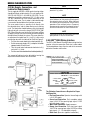
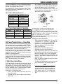
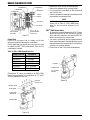
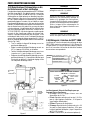
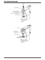
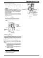
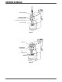
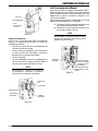
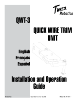
3.03 Air Supply, Connections, and
Lubrication Requirements
The air supply for the QRC
TM
-2000 nozzle cleaning station
should be filtered, unlubricated air. This unit requires 80-
100 PSI @ 8 CFM (5.5 – 6.8 BAR @ 225 LPM). The air
supply line should be a minimum of 1/4” I.D. with a male
1/4” NPT connection to fit the female connection in the
side of the logic cover. The air motor is lubricated through
a servo meter located below the lubricator reservoir.
The servo meter injects a quantity of oil directly into
the solenoid valves and air motor during each cleaning
cycle. The lubrication should be done using a light grade
hydraulic oil with a viscosity rating of 150 VC 15-20 (SAE
5W). When filling the reservoir for the first time or refilling
an empty reservoir, you must manually prime the pump to
distribute the oil through the system. The servo meter has
an adjustment that goes from 0 (-) to 45 (+) clicks and a
push button to prime the lubricant oil. Refer to Figure 2.
Pull the servo meter knob to the unlock position (A).
Set the servo meter knob at 45 (+) and press the button
appromimately 50 to 60 times.
Turn the servo meter knob counter-clockwise to 0 (-)
and set at 3 (+) clicks.
Push the servo meter knob back into the locked position (C).
The amount of lubricant can be adjusted by turning the
adjustment knob located on the servo meter.
•
•
•
•
LUBRICATOR
RESERVOIR
SERVO
METER
Figure 2
SERVO
METER
KNOB
PRIMER
PUSH
BUTTON
NOTE
Do not run unit without lubricant oil. If unit runs
out of lubricant oil, the motor will lock up and
the solenoid valves will stick. When lubricant
oil is added you must prime the unit and check
operation of the solenoid valves. Permanent
damage can be caused to the solenoid valves if
the unit is allowed to run out of lubricant oil.
NOTE
Lubricator Reservoir oil must have a vent in the
open position. If not, oil will not flow.
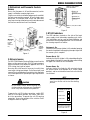
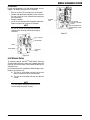
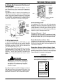
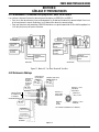
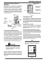
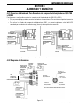
3.04 QRC
TM
-2000 Wiring Interface
The QRC
TM
-2000 Nozzle Cleaning Station wiring interface
requires a five wire connection. Each wire is color-coded.
The drawing below shows the wire color to its connector
pin/socket number and function.
The Following Connections are Required for Proper
Unit Operation:
Red Lead Connection: Operates internal logic with
a +24 V DC supply.
Green Lead Connection: Cycle complete output
signal (+24 V DC for sourcing logic signal; 0 V DC
for sinking logic signal).
White Lead Connection: Supply common.
Orange Lead Connection: Cycle start input signal
+24 V DC for sourcing logic signal; 0 V DC for sinking
logic signal. (.5 - 1.0 second pulse signal)
Black Lead: Spare wire (optional connection).
•
•
•
•
•
NOTE
The QRC2000 nozzle cleaning station is factory
preset at 3 (+) clicks.
TURN
(ADJUST)
RED: +24 VOLTS DC SUPPLY
GREEN: UNCLAMP SYMBOL
WHITE: SUPPLY COMMON
ORANGE: +24 VOLTS DC START SIGNAL
BLACK: SPARE/OPTION
4. START SIGNAL
(ORANGE)
5. OPTION
(BLACK)
ENSURE PROPER INTERFACE HAS BEEN MADE OR DAMAGE
MAY OCCUR
2. +24 VDC
SUPPLY (READ)
1. COMMON
(WHITE)
3. JAWS UNCLAMPED
(GREEN)
Figure 3
ROBOTIC
CONTROL

nozzle cleaning station
3-9
SM-QRC-2000
INSTALLATION AND OPERATION
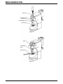
3.05 Electrical and Pneumatic Controls
Access
Ensure that the power is off and disconnected, and air
supply is off before removing logic cover.
To gain access to the circuit board and pneumatic manifold,
the logic cover must be removed. To free the logic cover
loosen four 10-24 button head screws and slide cover
away from cleaning station being careful not to disconnect
the interface connections from circuit board.
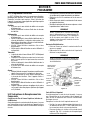
3.06 Logic Inverse
The QRC
TM
-2000 Nozzle Cleaning Station comes from the
factory set for sourcing (high) +24 V DC input or output.
Some installations may require the opposite of this or 0
V DC sinking (low) input or output.
Accessing the circuit board is necessary to switch from
sourcing to sinking input/output. On the lower right hand
corner of the circuit board are two switches that need to be
set to correspond to the input/output signal requirement
as shown.
CAUTION
Do not switch circuit board sourcing and
sinking switches with power on. Damage will
occur. Only move switches with power off.
To operate the unit ON sinking connection, switch SW1
must be in the down position, and switch SW2 must
be in the up position. To operate the unit ON sourcing
connection, reverse the position of the switches. Refer
to diagram shown on Figure 5.
SW2
SWITCH 2 (SW2) OUTPUT
JAWS UNCLAMPED
SINKING (UP)
SOURCING (DOWN)
SOURCING (UP)
SINKING (DOWN)
SWITCH 1 (SW1) INPUT START
SIGNAL
SW1
Figure 5
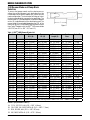
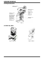
3.07 LED Indicators
The LED indicators located on the side of the logic
cover, supply visual information regarding cycle status.
This information may be used for both installation and
maintenance to verify proper operation. The LED indicates
the cleaning sequence as follows:
Unclamped - On
Indicates that the clamp cylinder is fully extended, opening
the nozzle clamp block and supplying an output signal that
the reamer cycle is complete.
Reamer Ahead - Off
Indicates that the lift cylinder is fully extended putting the
reamer blade at the top of its reaming stroke and activating
the upper limit switch on the circuit board.
Reamer Home - On
Indicates that the lift cylinder has fully retracted, placing
the reamer blade at the bottom of its stroke (home
position), and has activated the lower limit switch on the
circuit board.
NOTE
Both the
Unclamped
and
Reamer Home Lights
must be on for the unit to start the cleaning
process.
CLEANING SEQUENCE
UNCLAMPED
REAMER AHEAD
REAMER HOME
CAUTION
ENSURE PROPER INTERFACE
HAS BEEN MADE OR DAMAGE
MAY OCCUR. READ TECHNICAL
GUIDE BEFORE START-UP.
Figure 6
LOGIC
COVER
NO. 10-24
X 1/2” LG.
BUTTON
HEAD
SCREW
(4 EA.)
SOLENOID
VALVE (2 EA)
CIRCUIT
BOARD
NO. 10-24
X 1/2” LG.
BUTTON
HEAD
SCREW (4
EA.)
NO.
10X1/2”
LG
THREAD
FORMING
SCREW
(2 EA)
Figure 4

nozzle cleaning station
3-10
SM-QRC-2000
INSTALLATION AND OPERATION
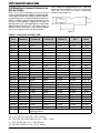
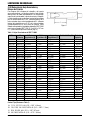
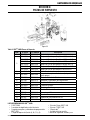
3.08 Reamer Blade and Clamp Block
Selection
To ensure that proper nozzle and tip cleaning occurs
without loss of tip alignment, each application must be
customized to fit the specific robotic gun, contact tip, and
nozzle configuration. The chart below will help you select
the best reamer blade for your particular application. The
reamer blade O.D. (outside diameter) selected will depend
on the I.D. (inside diameter) of the nozzle being used. The
reamer blade I.D. used would depend on the O.D. of the
contact tip. All QRC
TM
-2000 Nozzle Cleaning Stations come
from Tweco
®
Robotics with the QRC
TM
-100 reamer blade
(.620”/15,7mm O.D. x .422” / 10,7mm I.D.).
Figure 7
Part No. Stock No. Reamer
O.D. (A)
Reamer
I.D. (B)
Reamer
Length (C)
Nozzle
Bore
Contact Tip
QRC-100 3500-1275 .620” (15,7mm) .422” (10,7mm) 1.25” (31,7mm) 5/8” (15,9mm) A, B, C, & D
QRC-101 3500-1276 .494” (12,5mm) .344” (8,7mm) 1.25” (31,7mm) 1/2” (12,7mm) A & B
QRC-102 3500-1277 .485” (12,3mm) .344” (8,7mm) 1.12” (28,4mm) 1/2” (12,7mm) A & B
QRC-103 3500-1278 .368” (9,3mm) .281” (7,1mm) .94” (23,8mm) 3/8” (9,5mm) A
QRC-104 3500-1279 .734” (18,6mm) .530” (13,5mm) 2.08” (52,8mm) 3/4” (19,1mm) A, B, C, & D
QRC-105 3500-1280 .620” (15,7mm) .344” (8,7mm) 1.25” (31,7mm) 5/8” (15,9mm) A & B
QRC-106 3500-1290 .368” (9,3mm) .270” (6,9mm) .94” (23,8mm) 3/8” (9,5mm) A
QRC-107 3500-1281 .604” (15,3mm) .438” (11,1mm) 1.25” (31,7mm) 5/8” (15,9mm) A, B, C, & D
QRC-108 3500-1282 .505” (12,8mm) .344” (8,7mm) 1.27” (32,2mm) 5/8” (15,9mm) A & B
QRC-109 3500-1283 .620” (15,7mm) .344” (8,7mm) 1.25” (31,7mm) 5/8” (15,9mm) A & B
QRC-110 3500-1284 .620” (15,7mm) .296” (7,5mm) 1.25” (31,7mm) 5/8” (15,9mm) A & B
QRC-111 3500-1285 .734” (18,6mm) .296” (7,5mm) 1.84” (46,7mm) 3/4” (19,1mm) A & B
QRC-112 3500-1286 .620” (15,7mm) .360” (9,1mm) 1.00” (25,4mm) 5/8” (15,9mm) A, B, & C
QRC-113 3500-1287 .734” (18,6mm) .360” (9,1mm) 1.84” (46,7mm) 3/4” (19,1mm) A, B, & C
QRC-114 3500-1288 .620” (15,7mm) .390” (9,9mm) 1.25” (31,7mm) 5/8” (15,9mm) A, B, C, & D
QRC-115 3500-1289 .734” (18,6mm) .390” (9,9mm) 1.84” (46,7mm) 3/4” (19,1mm) A, B, C, & D
QRC-116 3500-1291 .494” (12,5mm) .359” (9,12mm) 1.08” (27,4mm) 1/2” (12,7mm) A, B, & C
QRC-119 3500-1297 .620” (15,7mm) .312” (7,9mm) 1.053” (26,7mm) 5/8” (15,9mm) A & B
QRC-120 3500-1298 .620” (15,7mm) .312” (7,9mm) 1.128” (28,6mm) 5/8” (15,9mm) A & B
QRC-121 3500-1299 .485” (12,3mm) .312” (7,9mm) .73” (18,5mm) 1/2” (12,7mm) A & B
QRC-121S 3500-1274 .485” (12,3mm) .374” (9,5mm) .84” (21,3mm) 1/2” (12,7mm) A, B, & C
QRC-122 3500-1260 .620” (15,7mm) .390” (9,9mm) 1.25” (31,7mm) 5/8” (15,9mm) A, B, C, & D
QRC-123 3500-1261 .552” (14,2mm) .390” (9,9mm) 2.26” (57,4mm) 5/8” (15,9mm) A, B, C, & D
QRC-124 3500-1262 .485” (12,3mm) .344” (8,7mm) ?.84” (21,3mm) 1/2” (12,7mm) A & B
QRC-125 3500-1259 .485” (12,3mm) .390” (9,9mm) 1.25” (31,7mm) 1/2” (12,7mm) A, B, C, & D
QRC-126 3500-1258 .485” (12,3mm) .360” (9,1mm) 1.08” (27,4mm) 1/2” (12,7mm) A, B, C
QRC-127 3500-1253 .528” (13,4mm) .360” (9,1mm) 1.08” (27,4mm) 5/8” (15,9mm) A, B, C
QRC-ABZ 3500-1273 Adapter for use on Binzel cleaning station in order to use Tweco
®
Robotics reamer blades.
Contact Tips (Reference Table 1)
A 11, 14, 14T, EL11 & AL (O.D. = .250” / 6,3mm)
B 11H, 11RS, 14H. 14RS, 14RZ & AL (O.D. = .283” / 7,1mm)
C EL16, EL16RS, & AL (O.D. = .345” / 8,7mm)
D
16S, 16RS, 16RZ & AL (O.D. = .375” / 9,5mm)
Table 1: QRC
TM
-2000 Reamer Blades List

nozzle cleaning station
3-11
SM-QRC-2000
INSTALLATION AND OPERATION
The other variable part in the QRC
TM
-2000 Nozzle Cleaning
Station is the clamp block set. There are five clamp blocks
available. Please refer to Tables 2 and 3.
The clamp block “B” comes assembled on all QRC
TM
-2000
Nozzle Cleaning Station. Clamp blocks A, C, D, and E are
also supplied with the unit.
Table 2: QRC
TM
-2000 Clamp Blocks List
Clamp Block O. D. Fits Nizzels
QRC2102-A .938” (23,8mm)
QRC2102-B 1” (25,4mm)
QRC2102-C 1.062” (27,0mm)
QRC2102-D 1.125” (28,6mm)
QRC2102-E .875” (22,2mm)
QRC2102-F .787” (20,0mm)
Table 3: Tweco
®
Robotic Nozzles vs. Clamp Block
Nozzle Nozzle O.D. Clamp Block
REL21 Series .875” (22,2mm) QRC-2102-E
REL24CT Series 1” (25,4mm) QRC-2102-B
RWC24 Series 1” (25,4mm) QRC-2102-B
RWC26 Series 1.062” (27,0mm) QRC-2102-C
3.09 Tweco
®
Robotic Nozzles vs. Clamp Block
Program the robot to position the Mig nozzle directly above
and centered to the reamer blade above the QRC
TM
-2000.
Insert the nozzle to the required depth to allow complete
cleaning of the tip and nozzle without damaging the torch
consumable parts. (Please refer to section 3.11).
At this time the cycle start signal (pulse .5 to 1.0 seconds)
should be sent to the QRC
TM
-2000 from the robotic
controller. Then the QRC
TM
-2000 will clamp the nozzle and
perform the cleaning operation.
Once the reamer completes the cleaning cycle, the cleaning
station will send a cycle complete signal back to the robot
controller. At this time, the torch is removed from the
QRC
TM
-2000 and the work cycle continues.
3.10 Air Flow Control Valve
The air flow control valve provides an adjustment for the
reamer blade feed rate. The amount of spatter buildup
will determine the required reamer blade feed rate. The
heavier the spatter, the slower the reamer blade feed
rate that should be used. If a smaller amount of spatter
accumulates, the feed rate can be set faster.
Adjusting the air flow control valve:
There is an air flow control valve inside the unit as
shown in Figure 8.
The feed rate may require adjusting for different
applications.
•
•
ADJUSTING
KNOB
LOCKING
NUT
INCREASE
FEED RATE
DECREASE
FEED RATE
Figure 8
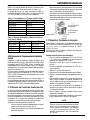
3.11 Nozzle and Insertion Parameter
All QRC
TM
-2000 Nozzle Cleaning Stations come from
Tweco
®
Robotics with the QRC-100 reamer blade
(.620”/15,7mm O.D. x .422” / 10,7mm I.D.) and clamp
block “B” (QRC2102-B / 1”(25,4mm)).
Please make sure that the reamer blade and clamp block
fit the need of your application.
Setting up the Torch with Gauges
There are three sizes of gauges (1/2” (12,7mm), 5/8”
(15,9mm) and 3/4” (19,1mm)). These gauges are
available as a set under Part No. QRC
TM
-PG2.
Determine O.D. of reamer blade being used.
Slip proper gauge on O.D. of reamer blade.
Screw in tip index shaft.
Determine O.D. of contact tip being used.
Slip proper alignment sleeve on pointer.
Bring torch down to where the I.D. of contact tip
touches pointer, push alignment sleeve up and over
contact tip to gauge if torch is set at 90 degrees.
Once this is established, back the torch off from the
pointer to allow room to remove the pointer and
alignment sleeve.
Bring the torch back down to where the nozzle
touches top of the gauge.
This allows the programmer to set up for the stroke
of the reamer blade in the cleaning sequence.
NOTE
Using a flush or protruded nozzle, adjust the
reamer blade stroke, leaving a gap between
the nozzle and the top of the gauge. For
flush nozzles: leave a 1/8” (3,2mm) gap.
For protruded nozzles: leave a 1/4” (6,4mm)
gap.
•
•
•
•
•
•
•
•
•
•
To increase the reamer blade feed rate, unscrew the
nut and rotate the valve knob counter-clockwise.
After the adjustment, lock the valve knob nut.
To decrease the reamer blade feed rate, unscrew the
nut and rotate the valve knob clockwise. After the
adjustment, lock the valve knob nut.
•
•

nozzle cleaning station
3-12
SM-QRC-2000
INSTALLATION AND OPERATION
CONTACT TIP
ALIGNMENT SLEEVE
TIP INDEX SHAFT
PROGRAMMING GAUGE
REAMER BLADE
NOZZLE
PROGRAMMING
GAUGE
REAMER BLADE
Figure 9
Figure 10

nozzle cleaning station
4-13
SM-QRC-2000
WIRING AND PNEUMATIC
SECTION 4:
WIRING AND PNEUMATIC
4.01 Wiring for the QRM-100 and QRM-3 Anti-spatter Mist Applicator
The drawings below show the QRM-100 and QRM-3 wiring connections.
For a sinking connection, the wires must be connected to positions 5 and 2. For sourcing connection, the wires
must be connected to positions 5 and 3.
To operate the QRM-100 Anti-Spatter Mist Applicator, a timed 24 V DC signal must be applied to the black lead
(spare) of the interface receptacle.
•
•
MOTOR & CLAMP
SOLENOID VALVE
SPINDLE LIFT
SOLENOID VALVE
PIN #5
PIN #3
ANTISPATTER UNIT
24DC
MOTOR & CLAMP
SOLENOID VALVE
SPINDLE LIFT
SOLENOID VALVE
PIN #5
PIN #2
ANTISPATTER UNIT
24DC
SOURCING SINKING
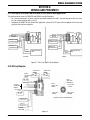
4.02 Wiring Diagram
Figure 12
LOWER LIMIT
SWITCH
UPPER LIMIT
SWITCH
CLAMP
RETURN LIMIT
SWITCH
NOT USED
START SIGNAL
COMMON
+24VDC
JAWS UNCLAMPED
OPTIONAL EQUIPMENT
SEE 5 PIN
CONNECTOR
WIRING
RESET SWITCH
MOTOR AND CLAMP
SOLENOID VALVE
SPINDLE LIFT
SOLENOID VALVE
OPTIONAL
EQUIPMENT
PIN #4
(ORG) START
SIGNAL
PIN #5 (BLK)
OPTION
PIN #3
(GRN) JAWS
UNCLAMPED
PIN #2 (RED)
+24 VDC
PIN #1 (WHT)
COMMON
EXTERNAL VIEW OF 5-PIN CONNECTOR
Figure 11: Pin #1 on Top/Pin #6 on Bottom

nozzle cleaning station
4-14
SM-QRC-2000
WIRING AND PNEUMATIC
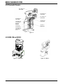
4.03 Pneumatic Diagram
Figure 13
1/8-27 NPT X 5/32
TUBE ELBOW
1/4-18 NPT X 1/4
TUBE ELBOW
1/4-18 NPT X 1/4
TUBE ADAPTER
FEED RATE
CONTROL
10-32 X 5/32
TUBE ADAPTER
1/8-27 NPT X 1/4
TUBE ELBOW
(5 EA.)
1/4-18 NPT X 1/4
TUBE ELBOW
5/32 TUBE X 5/32
TUBE ELBOW
1/4 TUBE X 1/4
TUBE ELBOW
1/4 TUBE “Y”
CONNECTOR
Figure 14: QRM-100 Figure 15: QRM-3
4.03 QRM-100 and QRM-3

nozzle cleaning station
5-15
SM-QRC-2000
MAINTENANCE
SECTION 5:
MAINTENANCE
5.01 Maintenance Schedule
The QRC
TM
-2000 will require a periodic maintenance
schedule to ensure an optimum service life. The following
maintenance checks are required. Depending on the use
of the unit, each specific application could require a more
extensive schedule.
Daily
Ensure incline housing area is clear of excessive
spatter.
Visually check oil level in lubricator reservoir.
Weekly
Ensure incline housing area is clear of excessive
spatter.
Visually check lubricating oil level in lubricator
reservoir. The life of the air motor is dependent on
a sufficient supply of lubricating oil. Replenish this
oil as needed.
Inspect air lines and connections for leaks.
Check interface cables for frayed connections or
bad wiring.
Quarterly
The QRC
TM
-2000 reamer blade life will depend on the
application.
At least quarterly the reamer blade should be inspected
for dullness, clogging and breakage.
Visually check lubricating oil level in lubricator reservoir.
Ensure incline housing area is clear of excessive spatter.
Yearly
The clamp block should be cleaned and inspected
for excessive wear and replaced if needed.
Visually check lubricating oil level in lubricator
reservoir. Replenish this oil as needed.
Inspect air lines and connections for leaks.
Check interface cables for frayed connections or
bad wiring.
Remove top plate and apply grease on cam slides
on top (V-Block) and side plates.
•
•
•
•
•
•
•
•
•
•
•
•
•
•
•
5.02 Component Replacement Instructions
Upper, Lower, and Jaw Stop Limit Switches
Ensure that the power is off and disconnected, and the air
supply is off before replacing the limit switches.
To replace the limit switches, loosen the screws that
connect the limit switch bracket to the manifold.
Disconnect the wiring for the limit switch that is being
replaced.
Remove the nut that connects the limit switch to the limit
switch bracket.
Replace the limit switches in reverse order
•
•
•
•
NOTE
Be sure to review the wiring diagram when
rewiring and disconnecting the limit switch (see
Figure 12). The limit switches are adjusted at
the factory. If an adjustment needs to be made,
please contact our factory technical center.
Reset Switch
Unscrew the nut that connects the limit switch to
bracket.
Disconnect the wiring from the circuit board and
replace it.
NOTE
Be sure to review the wiring diagram (Figure
12) when rewiring and disconnecting the reset
switch.
•
•
Circuit Board
Ensure that the power and air supply are off and
disconnected before replacing the circuit board.
Replace the circuit board in the following manner:
Once the power and air are disconnected from the
QRC
TM
-2000, carefully unplug all connectors from
the board.
Unscrew the two screws located on the circuit board.
(Fig. 17) The circuit board can now be replaced.
Install the new circuit board on the board insulator.
Once this has been completed, tighten the two circuit
board mounting screws.
Reconnect the connectors while referring to wiring
diagram to be sure the connections are in the
proper location.
CAUTION
Do not switch circuit board sourcing and
sinking switches with the power on. Damage
will occur. Only move the switches with the
power off.
•
•
•
•
•
LOWER
LIMIT
SWITCH
BRACKET
SCREW
LOCKING
NUT
SWITCH
BRACKET
JAW CLAMP
LIMIT
SWITCH
RESET
SWITCH
UPPER LIMIT
SWITCH
Figure 16

nozzle cleaning station
5-16
SM-QRC-2000
MAINTENANCE
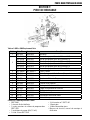
Clamp Block
Ensure that the power and air supply are off and
disconnected before replacing the clamp block.
Certain applications or normal wear may cause the need
to replace the QRC
TM
-2000 clamp block. There are five
clamp blocks available.
CIRCUIT BOARD
INSULATOR
NO. 10 S 1/2” LG.
THREAD-FORMING
SCREW (2 EA.)
SW1 SWITCH
SW2 SWITCH
CIRCUIT
BOARD
J5
CONNECTOR
Figure 17
J4 CONNECTOR
J3 CONNECTOR
J1 CONNECTOR
J2 CONNECTOR
Table 4: ORC
TM
-2000 Clamp Blocks List
Clamp Block O.D. Fits Nozzles
QRC2102-A .938” (23,8mm)
QRC2102-B 1” (25,4mm)
QRC2102-C 1.062” (27,0mm)
QRC2102-D 1.125” (28,6mm)
QRC2102-E .875” (22,2mm)
QRC2102-F .787” (20,0mm)
Clamp block “B” comes assembled on all QRC
TM
-2000
Nozzle Cleaning Station. The clamp blocks A, C, D, and E
are also supplied with the unit.
LOCATOR SPACER
CLAMP BLOCK
CLAMP BLOCK
LOCATOR PIN
REAMER BLADE
TOP PLATE
SCREWS (7 EA)
Figure 18
Remove the seven screws on three top plate.
Remove the top plate to the cleaning station.
Lift and rotate the clamp block so that the desired
sizes face the jaws.
Clean the components thoroughly and lubricate with
grease before reassembling them.
NOTE
Part numbers are stamped on clamp blocks.
Please refer to Table 4 - QRC
TM
2000 clamp
block list for the outside diameter of the
nozzle.
•
•
•
•
QRC
TM
-2000 Reamer Blade
To remove the reamer blade, place the 9/16” (14mm)
spanner wrench, part no. QRC-440, on the hex flats
at the end of the extension shaft and the QRC-441
wrench on the top of the reamer blade.
The cutter is removed by turning counterclockwise
when viewed from above. Considerable force may be
required to loosen the reamer blade since it tightens
naturally as the reamer operates.
Please refer to Table 1 for reamer blade options.
•
•
•
T-WRENCH
REAMER BLADE
9/16” SPANNER
WRENCH
Figure 19

nozzle cleaning station
5-17
SM-QRC-2000
MAINTENANCE
Air Solenoids
Ensure that the power is off and disconnected, and air
supply is off before replacing the air solenoids.
Refer to section 5.02 to remove the circuit board.
Remove and replace one solenoid at a time. Unscrew
the two screws on the air solenoid and unplug the
wire connectors.
Remove solenoid.
Install the new solenoid with the gasket and rewire.
Repeat sequence for the other air solenoid.
•
•
•
•
NOTE
Be sure to review the wiring and pneumatic
diagram when rewiring and disconnecting air
solenoids.
GASKET
AIR SOLENOID
M3 X 0.5 SCREW
AIR SOLENOID
ELECTRICAL
WIRES
Figure 20
5.03 Manual Setup
To manually operate the QRC
TM
-2000 Nozzle Cleaning
Station without electricity, connect air in proper place and
manually activate the two air valve buttons located on the
solenoid valves.
Each solenoid valve has a red button. Manually press each
button to activate the unit.
A) The left air valve button activates the up and
down lift movement of the reamer blade.
B) The right air valve button activates the spin and
clamp.
NOTE
The reset button should be pressed prior to
manual setup to reset all circuitry.
SOLENOID
VALVE
LEFT BUTTON ACTIVATES
(REAMER BLADE UP AND
DOWN)
RIGHT BUTTON
ACTIVATES (SPIN AND
CLAMP)
Figure 21

nozzle cleaning station
6-18
SM-QRC-2000
TROUBLESHOOTING
SECTION 6:
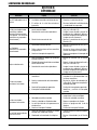
TROUBLESHOOTING
Problem Cause Solution
LED signals not activating
1. The unit is not receiving power. 1. Turn power on.
2. The unit is not getting air. 2. Turn air on.
3. Input voltage is incorrect. 3. Check input voltage and change if
required.
Reamer Blade/Air Motor stops
during operation (see also
Pneumatic functions not operating
properly)
1. Cutter feed rate is too fast. 1. Reduce cutter feed rate (see
section 3.10).
2. Excessive spatter buildup. 2. Clean affected area and adjust weld
parameters. Apply or increase
anti-spatter. Clean more often.
3. Incorrect air supply. 3. Adjust air supply (See section
3.03).
Pneumatic functions not operating
properly
1. Incorrect air supply. 1. Adjust air supply (see section
3.03).
2. Air line damage or obstructed and
air leaks.
2. Check lines for leaks and replace
hose if damaged.
3. Faulty reset switch. 3. Repair or replace reset switch.
Broken Reamer Blade
1. Wrong size reamer blade or clamp
block.
1. Check sizing (see section 3.08).
2. Reamer blade feed rate was set
too high.
2. Reduce cutter feed rate. (see
section 3.10).
3. Excessive spatter buildup. 3. Clean affected area and adjust weld
parameters. Apply or increase
anti-spatter. Clean more often.
Reamer Blade stays in down position
1. Damaged lift cylinder or air lines. 1. Reset switch defective.
2. Faulty or contaminated lift solenoid. 2. Check solenoid valves. Fix or
replace faulty solenoid.
3. Reset switch defective. 3. Replace reset switch.
4. Damaged limit switch. 4. Identify and replace faulty
switch.
Reamer Blade stays in up position
1. Reamer Blade is jammed. 1. Press Reset button and Inspect
Reamer Blade.
2. Faulty air solenoid. 2. Replace air solenoid.
3. Bad or dirty lift cylinder. 3. Fix or replace cylinder.
4. Cycle start signal held on. 4. Adjust cleaning cycle program.
5. Faulty limit switch. 5. Replace limit switch.
Cycle complete signal does not
activate
1. Faulty limit switch on lift cylinder
or clamping cylinder.
1. R epl ac e or r ea li gn r ead
switch(es).
2. Unit is not wired correctly. 2. Check wiring (see section 4).
La page est en cours de chargement...
La page est en cours de chargement...
La page est en cours de chargement...
La page est en cours de chargement...
La page est en cours de chargement...
La page est en cours de chargement...
La page est en cours de chargement...
La page est en cours de chargement...
La page est en cours de chargement...
La page est en cours de chargement...
La page est en cours de chargement...
La page est en cours de chargement...
La page est en cours de chargement...
La page est en cours de chargement...
La page est en cours de chargement...
La page est en cours de chargement...
La page est en cours de chargement...
La page est en cours de chargement...
La page est en cours de chargement...
La page est en cours de chargement...
La page est en cours de chargement...
La page est en cours de chargement...
La page est en cours de chargement...
La page est en cours de chargement...
La page est en cours de chargement...
La page est en cours de chargement...
La page est en cours de chargement...
La page est en cours de chargement...
La page est en cours de chargement...
La page est en cours de chargement...
La page est en cours de chargement...
La page est en cours de chargement...
La page est en cours de chargement...
La page est en cours de chargement...
La page est en cours de chargement...
La page est en cours de chargement...
La page est en cours de chargement...
La page est en cours de chargement...
La page est en cours de chargement...
La page est en cours de chargement...
La page est en cours de chargement...
La page est en cours de chargement...
La page est en cours de chargement...
La page est en cours de chargement...
La page est en cours de chargement...
La page est en cours de chargement...
La page est en cours de chargement...
La page est en cours de chargement...
La page est en cours de chargement...
La page est en cours de chargement...
La page est en cours de chargement...
La page est en cours de chargement...
-
 1
1
-
 2
2
-
 3
3
-
 4
4
-
 5
5
-
 6
6
-
 7
7
-
 8
8
-
 9
9
-
 10
10
-
 11
11
-
 12
12
-
 13
13
-
 14
14
-
 15
15
-
 16
16
-
 17
17
-
 18
18
-
 19
19
-
 20
20
-
 21
21
-
 22
22
-
 23
23
-
 24
24
-
 25
25
-
 26
26
-
 27
27
-
 28
28
-
 29
29
-
 30
30
-
 31
31
-
 32
32
-
 33
33
-
 34
34
-
 35
35
-
 36
36
-
 37
37
-
 38
38
-
 39
39
-
 40
40
-
 41
41
-
 42
42
-
 43
43
-
 44
44
-
 45
45
-
 46
46
-
 47
47
-
 48
48
-
 49
49
-
 50
50
-
 51
51
-
 52
52
-
 53
53
-
 54
54
-
 55
55
-
 56
56
-
 57
57
-
 58
58
-
 59
59
-
 60
60
-
 61
61
-
 62
62
-
 63
63
-
 64
64
-
 65
65
-
 66
66
-
 67
67
-
 68
68
-
 69
69
-
 70
70
-
 71
71
-
 72
72


Tweco Robotics QRC™-2000 Nozzle Cleaning Station Guide d'installation
- Taper
- Guide d'installation
dans d''autres langues
Documents connexes
-
 Tweco Robotics QRM-3 Solenoid Valve Assembly Guide d'installation
-
 Tweco Robotics QRC-3000LS QRC-3000IO Ultrasonic Nozzle Cleaning Station Manuel utilisateur
-
 Tweco Robotics QRP-IN TCP Check Tool Guide d'installation
-
 Tweco Robotics QWT-120 Wire Cutting Station Guide d'installation
-
 Tweco Robotics QRC™-2000 Nozzle Cleaning Station Guide d'installation
-
 Tweco Robotics QWT-3 Quick Wire Trim Unit Guide d'installation
-
Tweco Robotics Light Weight Quick Robotics Torch Guide d'installation
-
Tweco Robotics QRM-3 Anti-Spatter Sprayer Guide d'installation
-
 Tweco Robotics QRM-100 Anti-Spatter Mist Applicator Guide d'installation
-
 Tweco Robotics Quick Robotic Torch Guide d'installation


