
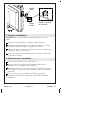
Installation Guide
Digital Interface
Français, page ″Français-1″
Español, página ″Español-1″
1143086-2-G

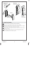
IMPORTANT INSTRUCTIONS
WARNING: When using electrical products, basic
precautions should always be followed, including the
following:
WARNING: Risk of electric shock. A qualified electrician
should route all electrical wiring.
WARNING: Risk of electric shock. Disconnect power before
servicing.
WARNING: Risk of injury or property damage. Please read
all instructions thoroughly before beginning installation.
NOTICE: Follow all plumbing, electrical, and building codes.
Specifications
Interface
Ambient Temperature Max 125°F (51.5°C)
Maximum Relative Humidity 100% condensing (External surface only)
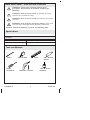
User Interface Cable Length 20’ (6.1 m)
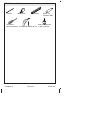
Tools and Materials
Pencil Level
Drill and 1/4" Drill Bit
Tape Measure
Phillips
Screwdriver
1-3/8" or 35 mm
Hole Saw
100% Silicone
Sealant
1143086-2-G 2 Kohler Co.

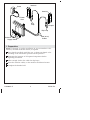
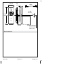
Roughing-In
Cable
3/4"
(19 mm)
Ø 1-3/8"
(35 mm)
Recommended
58" (1473 mm)
To Floor
7-3/4"
(197 mm)
2-11/16"
(68 mm)
18" (457 mm)
20' (6.1 m)
Kohler Co. 3 1143086-2-G

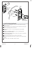
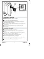
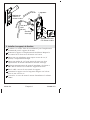
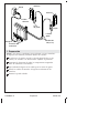
1. Preparation
NOTE: If desired, set up this installation to use two interfaces. One
interface, installed inside the shower, is required.
If not already installed, install the two- or three-port digital valve
according to the instructions packed with the product.
Determine the locations of all required components before
beginning installation.
Allow enough slack in the cables for drip loops.
Route the interface cable(s) to the interface installation location.
Complete the finished wall.
Coupler
Drip Loop
Drip
Loop
Power
Cord
Outlet
Interface
Interface
20' (6.1 m)
Cables
Outlets
Supply Inlets
1143086-2-G 4 Kohler Co.

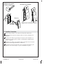
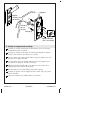
2. Install the Mounting Bracket
Refer to the ″Roughing-In″ section for recommended mounting
bracket location.
Hold the bracket at the installation location. Mark the center hole
and two mounting holes on the wall.
Using a hole saw, cut a 1-3/8″ (35 mm) hole at the marked
location.
Using a 1/4″ drill bit, drill holes at the two mounting-hole
locations. Install the anchors.
Generously apply 100% silicone sealant in the groove on the back
of the mounting bracket.
Pull the cable through the center hole of the bracket.
Position the bracket with the tabs up. Secure to the wall with the
screws.
Cover the screws with 100% silicone sealant.
Anchor
1-3/8"
(35 mm)
Hole
Tabs
Apply 100%
silicone sealant.
Apply 100%
silicone
sealant.
Kohler Co. 5 1143086-2-G

3. Install the Interface
Secure the O-ring to the back of the user interface.
Apply grease (provided) into both ends of the coupler.
Connect the cable from the wall and the interface into the coupler.
Ensure that the cables fully click into the coupler.
Feed the cable and coupler into the hole in the wall. Ensure that a
drip loop is made.
Hook the top of the interface onto the mounting bracket, then
press the bottom until it clicks in place.
Connect
the cables.
Coupler
Press to
click in place.
Hook onto
the bracket.
Apply grease
in both ends.
1143086-2-G 6 Kohler Co.

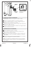
4. Complete the Installation
IMPORTANT! Make drip loops in all cables.
Press a split boot onto each interface cable.
Connect the interface cable to the valve. Ensure that the cable
fully clicks into the valve socket.
Press the boot over the connector and into the valve socket to seal
the connection.
If you only install one interface, insert a solid boot into the
unused socket.
5. Installation Checkout
Turn ON the water supply to the valve.
Check all connections for leaks and make any adjustments as
needed.
Plug in the valve. You should hear the valve power-up and the
power icon on the user interface will be lit.
If not already completed, refer to the digital interface
homeowners guide to set up the user interface.
NOTE: For more information about using the user interface and its
menus, refer to the ″Digital Interface Homeowners Guide.″
Press the power icon to turn ON the shower.
Slide the split boot onto
the interface cable.
Split
Boot
Solid
Boot
Kohler Co. 7 1143086-2-G

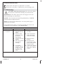
Installation Checkout (cont.)
Check for leaks and make any adjustments as needed.
Verify that the water flow is sufficient for your showering needs.
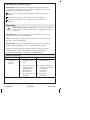
Troubleshooting
CAUTION: Risk of personal injury. The valve may contain
hot water; be careful when draining any residual water.
IMPORTANT! Turn off the power and water supply to the valve
before performing any maintenance.
NOTICE: Valve maintenance should be performed by a KOHLER
Authorized Service Representative.
NOTE: For service parts information, visit your product page at
kohler.com/serviceparts.
This troubleshooting guide is for general aid only. For service and
installation issues or concerns, call 1-800-4KOHLER.
Troubleshooting Table
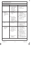
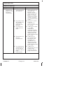
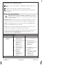
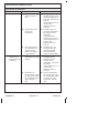
Symptoms Probable Cause Recommended Action
1. Control panel
is not lit.
A. Valve is not
plugged into the
outlet.
A. Plug the valve into
an outlet.
B. Interface cable
connections may
be loose or
disconnected.
B. Check all interface
cable connections,
connect if needed.
C. Circuit breaker has
tripped.
C. Reset the circuit
breaker.
D. The valve memory
may require
resetting.
D. Disconnect and
reconnect the valve
power cord from the
electrical outlet.
E. A ″straight-
through″ cable or
coupler was used
to connect the
interface to the
valve.
E. Connect the interface
to the valve using a
″cross-over″ cable or
coupler.
1143086-2-G 8 Kohler Co.

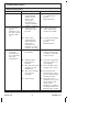
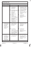
Troubleshooting (cont.)
Troubleshooting Table
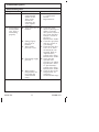
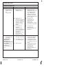
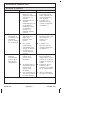
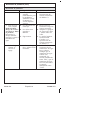
Symptoms Probable Cause Recommended Action
F. If none of the
recommended
actions for the
above issues
correct the
symptom, the
valve or interface
requires servicing.
F. Contact your Kohler
Co. Authorized
Service
Representative.
2. The interface
power
indicator is lit,
but the system
will not turn
on.
A. Interface cable
connections may
be loose.
A. Check all interface
cable connections,
connect if needed.
B. If the above
recommended
action does not
correct the
symptom, the
interface or valve
requires servicing.
B. Contact your Kohler
Co. Authorized
Service
Representative.
3. The interface
functions
normally but
no water flows
from the
components.
A. Valve outlets may
be blocked.
A. Check the valve
outlets for blockage
or debris. Clean the
outlet screens.
B. Fittings/Spray
faces may be
blocked.
B. Clean the sprayfaces
and any screens in
your fittings.
C. Hot and cold water
supplies are not
turned ON.
C. Turn ON the water
supply to the valve.
D. The valve memory
may require
resetting.
D. Disconnect and
reconnect the valve
power cord from the
electrical outlet.
E. System error. E. Check the user
interface for an error
code. Refer to the
″Error Code
Diagnosis″ section in
the Digital Interface
Homeowners Guide.
Kohler Co. 9 1143086-2-G

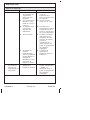
Troubleshooting (cont.)
Troubleshooting Table
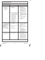
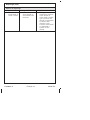
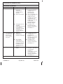
Symptoms Probable Cause Recommended Action
F. If none of the
recommended
actions for the
above issues
correct the
symptom, the
valve requires
servicing.
F. Contact your Kohler
Co. Authorized
Service
Representative.
4. Maximum
blend
temperature
too hot or too
cold.
A. Incorrect maximum
temperature
setting.
A. Refer to the
″Temperature – Set
the Maximum″
section in the Digital
Interface
Homeowners Guide.
B. If the above
recommended
action does not
correct the
symptom, the
interface or valve
requires servicing.
B. Contact your Kohler
Co. Authorized
Service
Representative.
5. Continuous
flow.
A. System will not
switch off.
A. Turn off the water
and power supply
and contact your
Kohler Co.
Authorized Service
Representative.
6. Only cold
water flows
from the
outlets.
A. Hot water supply
is either not turned
ON or not
connected to the
valve inlet.
A. Check if the hot
water supply is
turned ON and
connected to the
valve inlet.
B. Hot water inlet is
blocked.
B. Check the hot water
inlet screen for
blockage. Clean or
replace the inlet
screen. Refer to the
Valve Homeowners
Guide.
C. The hot water
supply is
exhausted.
C. Allow time for the
water heater to come
up to temperature.
1143086-2-G 10 Kohler Co.

Troubleshooting (cont.)
Troubleshooting Table
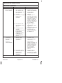
Symptoms Probable Cause Recommended Action
D. If none of the
recommended
actions for the
above issues
correct the
symptom, the
valve requires
servicing.
D. Contact your Kohler
Co. Authorized
Service
Representative.
7. Fluctuating or
reduced flow
rate. Valve is
functioning
properly.
A. Valve inlets may be
blocked.
A. Check the valve
inlets for blockage or
debris. Clean the
inlet screens. Refer to
the ″Clean the Inlet
Screens″ section in
the Valve
Homeowners Guide.
B. Fittings/Spray
faces may be
blocked.
B. Clean the sprayfaces
and any screens in
your fittings.
C. Water outlet
pressure is low.
C. Check that the flow
rate is at or above
the minimum rate
required. Refer to
″Specifications″
section in the Valve
Homeowners Guide.
D. Fluctuating supply
pressure.
D. Verify that the
dynamic inlet
pressures are within
specifications. Refer
to ″Specifications″
section in the Valve
Homeowners Guide.
E. Water supply
temperatures are
not within the
recommended
range.
E. Check if inlet water
temperatures are
within the
recommended range.
Kohler Co. 11 1143086-2-G

Troubleshooting (cont.)
Troubleshooting Table
Symptoms Probable Cause Recommended Action
8. Blend
temperature
drift or
temperature
cycling.
A. Fluctuating water
supply
temperature.
A. Check the inlet
temperature
differentials and
verify that they are
sufficient. Refer to
″Specifications″
section in the Valve
Homeowners Guide.
B. Pressure difference
greater than 5 psi
(34.5 kPa) between
the hot and cold
supply lines.
B. Install pressure
regulators to bring
the supplies within 5
psi (34.5 kPa) of each
other.
C. If none of the
recommended
actions for the
above issues
correct the
symptom, the
valve requires
servicing.
C. Contact your Kohler
Co. Authorized
Service
Representative.
9. Water leaking
from the valve.
CAUTION: Risk
of personal injury
or product
damage. Turn off
the main power
and water supply.
A. Connections are
not secure.
A. Check all
connections. Make
adjustments as
needed.
B. Seals are worn or
damaged.
B. Order a seal service
pack and replace all
seals.
C. Internal leak. C. Unit requires
overhaul. Contact
your Kohler Co.
Authorized Service
Representative.
10. Hot water only,
the valve shuts
down.
A. Hot and cold lines
are reversed.
A. Switch hot and cold
water supply
connections. Verify
that the hot water
supply is connected
to the ″Hot″ inlet and
the cold water
supply is connected
to the ″Cold″ inlet.
1143086-2-G 12 Kohler Co.

Guide d’installation
Interface numérique
INSTRUCTIONS IMPORTANTES
AVERTISSEMENT: Lors de l’utilisation de produits
électriques, toujours observer les précautions de base,
notamment:
AVERTISSEMENT: Risque de choc électrique. Tout le
câblage électrique doit être réalisé par un électricien qualifié.
AVERTISSEMENT: Risque de choc électrique. Déconnecter
l’alimentation électrique avant d’effectuer un entretien.
AVERTISSEMENT: Risque de blessures ou
d’endommagement du matériel. Lire toutes les instructions
avec attention avant de commencer l’installation.
AVIS: Respecter tous les codes de plomberie, d’électricité et de
construction.
Spécifications
Interface
Température ambiante Max 125°F (51,5°C)
Humidité relative maximale 100% avec condensation (surface externe
seulement)
Longueur de câble de
l’interface utilisateur
20’ (6,1 m)
Kohler Co. Français-1 1143086-2-G

Outils et matériel
Crayon Niveau
Perceuse et mèche de 1/4"
Mètre ruban
Tournevis à
pointe cruciforme
Scie cylindrique de
1-3/8" ou 35 mm
Mastic à la
silicone à 100%
1143086-2-G Français-2 Kohler Co.

Raccordement
Câble
58" (1473 mm)
recommandés
jusqu'au sol
3/4"
(19 mm)
Ø 1-3/8"
(35 mm)
7-3/4"
(197 mm)
2-11/16"
(68 mm)
18" (457 mm)
20' (6.1 m)
Kohler Co. Français-3 1143086-2-G

1. Préparation
REMARQUE: Si souhaité, configurer cette installation pour utiliser
deux interfaces. Une interface, installée à l’intérieur de la douche, est
requise.
Si cela n’a pas encore été effectué, installer la vanne numérique à
deux ou trois ports selon les instructions accompagnant le
produit.
Déterminer les emplacements de tous les composants requis avant
de commencer l’installation.
Laisser assez de jeu dans les câbles pour les boules
d’égouttement.
Acheminer le(s) câble(s) d’interface sur l’emplacement
d’installation de l’interface.
Terminer le mur fini.
Raccord
Anneau
d'écoulement
Anneau
d'écoulement
Cordon
d'alimentation
Sortie
Interface
Interface
Câbles
20' (6,1 m)
Sorties
Entrées
d'alimentation
1143086-2-G Français-4 Kohler Co.

2. Installer le support de fixation
Se référer à la section ″Plan de raccordement″ pour l’emplacement
recommandé pour le support de fixation.
Maintenir le support à l’emplacement d’installation. Marquer le
trou central et les deux trous de fixation sur le mur.
Utiliser une scie cylindrique pour couper un trou de 1-3/8″
(35 mm) à l’emplacement marqué.
Utiliser une mèche de 1/4″ pour percer des trous aux deux
emplacements de fixation. Installer les chevilles d’ancrage.
Appliquer généreusement du mastic d’étanchéité à la silicone à
100% dans la rainure sur l’arrière du support de fixation.
Tirer le câble à travers le trou central du support.
Positionner le support avec les languettes dirigées vers le haut.
Fixer au mur avec les vis.
Couvrir les vis avec du mastic le mastic d’étanchéité à la silicone
à 100%.
Cheville
d'ancrage
Trou de
1-3/8"
(35 mm)
Languettes
Appliquer du mastic
à la silicone à 100%.
Appliquer du
mastic à la
silicone à 100%.
Kohler Co. Français-5 1143086-2-G

3. Installer l’interface
Fixer le joint torique sur l’arrière de l’interface utilisateur.
Appliquer de la graisse (fournie) dans les deux extrémités du
coupleur.
Connecter le câble en provenance du mur et de l’interface au
coupleur. S’assurer que les câbles s’enclenchent complètement
dans le coupleur.
Alimenter le câble et le coupleur dans le trou du mur. S’assurer
qu’une boucle d’égouttement est effectuée.
Accrocher le haut de l’interface sur le support de fixation, puis
appuyer sur le bas jusqu’à ce qu’il s’enclenche en place.
Connecter
les câbles.
Raccord
Appuyer pour enclencher en place.
Accrocher sur le support.
Appliquer de la graisse
aux deux extrémités.
1143086-2-G Français-6 Kohler Co.

4. Terminer l’installation
IMPORTANT! Créer des boucles d’égouttement dans tous les
câbles.
Appuyer une gaine fendue sur chaque câble d’interface.
Raccorder le câble d’interface à la vanne. S’assurer que le câble
s’enclenche entièrement dans la douille de la vanne.
Enfoncer la gaine par-dessus le connecteur et dans la douille de la
vanne pour sceller la connexion.
Si une seule interface est installée, insérer une gaine robuste dans
la douille non utilisée.
5. Vérification de l’installation
Ouvrir l’alimentation en eau vers la vanne.
Inspecter tous les raccords pour y rechercher des fuites et
effectuer tous les réglages selon les besoins.
Brancher la vanne. La mise en marche de la vanne doit pouvoir
être entendue et l’icône de mise en marche s’allume sur l’interface
utilisateur.
Si cela n’a pas encore été effectué, consulter le guide du
propriétaire de l’interface numérique pour installer l’interface
utilisateur.
Faire glisser la douille
fendue sur le câble
de l'interface.
Douille
fendue
Douille
solide
Kohler Co. Français-7 1143086-2-G

Vérification de l’installation (cont.)
REMARQUE: Pour obtenir de l’information supplémentaire sur
l’utilisation de l’interface et sur ses menus, consulter le ″Guide du
propriétaire de l’interface numérique″.
Appuyer sur l’icône Marche/Arrêt pour mettre la douche en
marche.
Rechercher des fuites et effectuer les réglages nécessaires.
Vérifier que le débit d’eau est suffisant pour les besoins de
douche.
Dépannage
ATTENTION: Risque de blessures. La vanne peut contenir
de l’eau chaude; faire attention lors de la purge de toute eau
résiduelle.
IMPORTANT! Couper l’alimentation et l’arrivée d’eau à la vanne
avant de procéder à une maintenance.
AVIS: L’entretien des vannes doit être effectué par un représentant
technique agréé de KOHLER.
REMARQUE: Pour tout renseignement sur les pièces de rechange,
visiter la page du produit sur le site kohler.com/serviceparts.
Ce guide de dépannage est seulement destiné à fournir une aide
d’ordre général. Pour des problèmes ou questions concernant
l’entretien et l’installation, composer le 1-800-4KOHLER.
Tableau de dépannage
Symptômes Cause probable Action recommandée
1. Le panneau de
commande
n’est pas
allumé.
A. La vanne n’est pas
branchée dans la
prise.
A. Brancher la vanne
dans une prise.
B. Les connexions du
câble d’interface
pourraient être
desserrées ou
déconnectées.
B. Inspecter toutes les
connexions du câble
d’interface et
raccorder si
nécessaire.
C. Le disjoncteur s’est
déclenché.
C. Réarmer le
disjoncteur.
1143086-2-G Français-8 Kohler Co.
La page est en cours de chargement...
La page est en cours de chargement...
La page est en cours de chargement...
La page est en cours de chargement...
La page est en cours de chargement...
La page est en cours de chargement...
La page est en cours de chargement...
La page est en cours de chargement...
La page est en cours de chargement...
La page est en cours de chargement...
La page est en cours de chargement...
La page est en cours de chargement...
La page est en cours de chargement...
La page est en cours de chargement...
La page est en cours de chargement...
La page est en cours de chargement...
La page est en cours de chargement...
La page est en cours de chargement...
La page est en cours de chargement...
La page est en cours de chargement...
-
 1
1
-
 2
2
-
 3
3
-
 4
4
-
 5
5
-
 6
6
-
 7
7
-
 8
8
-
 9
9
-
 10
10
-
 11
11
-
 12
12
-
 13
13
-
 14
14
-
 15
15
-
 16
16
-
 17
17
-
 18
18
-
 19
19
-
 20
20
-
 21
21
-
 22
22
-
 23
23
-
 24
24
-
 25
25
-
 26
26
-
 27
27
-
 28
28
-
 29
29
-
 30
30
-
 31
31
-
 32
32
-
 33
33
-
 34
34
-
 35
35
-
 36
36
-
 37
37
-
 38
38
-
 39
39
-
 40
40


dans d''autres langues
- English: Kohler 558-1CP Installation guide
- español: Kohler 558-1CP Guía de instalación
Documents connexes
-
Kohler 558-E-1CP Guide d'installation
-
Kohler 557-K-NA Guide d'installation
-
-
-
-
Kohler K-1849-GVBCW-0 Guide d'installation
-
-
Kohler K-1167-GVR-96 Guide d'installation
-
-