Whirlpool XBP 40TC SX 2V FB Mode d'emploi
- Taper
- Mode d'emploi

C
H
C
H
Piano di cottura
Istruzioni per l'uso e l'installazione 1
Hob
Instructions for use and installation 8
Plan de cuisson
Instruction pour l'utilisation et l'installation 15
Kochplatte
Gebrauchs- und Installationsanleitungen 22
kookplaat
Instructies voor het gebruik en installeren 29
Planos de cocción
Instrucciones para el uso y la instalación 36
Planos de cozedura
Instruções para o uso e a instalação 43

1
Avvertenze................................................................................................................…………………................... pag. 1
Descrizione del piano di cottura..................................………………………..........………………………............…......“ 2
Istruzioni per l’uso - Bruciatori gas............................…………………………………………………....................…......“ 3
Pulizia e manutenzione................................................................……………………………………............................“ 3-4
Istruzioni per l’installatore..................................................…………..………………………......................….........…..“ 4
Posizionamento.........................................................................................................................................................“ 4
Installazione dei piani di cottura..........................................................……………………………………….................“ 5
Collegamento alimentazione gas........................................................……………………………………….................“ 6
Adattamento ai diversi tipi di gas..........................................................…………………………………………............“ 6
Regolazione minimi..............................................................................………………………………..…………..........“ 6
Collegamento elettrico..........................................................................…………………………………………............“ 6-7
Caratteristiche dei bruciatori ed ugelli.............................................…………………………………………..................“ 7
QUESTE ISTRUZIONI SONO VALIDE SOLO PER I PAESI DI DESTINAZIONE I CUI SIMBOLI FIGURANO SUL LIBRETTO
E SULLA TARGA MATRICOLA DELL’APPARECCHIO.
1. Questo apparecchio è stato concepito per essere
utilizzato da privati per un uso di tipo non
professionale all’interno di abitazione comune.
2. Leggere attentamente le avvertenze contenute nel
presente libretto istruzioni, in quanto forniscono
importanti indicazioni riguardanti la sicurezza di
installazione, d’uso e di manutenzione. Conservare
con cura questo libretto per ogni eventuale
consultazione.
3. Dopo aver tolto l’imballaggio assicurarsi dell’integrità
dell’apparecchio. In caso di dubbio non utilizzare
l’apparecchio e rivolgersi a personale professionalmente
qualificato.
4. Non lasciare l’apparecchio inutilmente inserito. Spegnere
l’interruttore generale dell’apparecchio quando lo stesso
non è utilizzato e chiudere il rubinetto del gas.
5. È necessario che tutte le operazioni relative
all’installazione e alla regolazione vengano eseguite da
personale qualificato, secondo le norme in vigore. Le
istruzioni specifiche sono descritte nella sezione riservata
all’installatore.
6. Verificare periodicamente il buono stato del tubo di
collegamento gas e farlo sostituire da personale qualificato
non appena presenta qualche anomalia.
AVVERTENZE
7. Il cavo di alimentazione ed il tubo di collegamento gas di
questo apparecchio non devono essere sostituiti
dall’utente. In caso di danneggiamento e di eventuale
sostituzione rivolgersi esclusivamente ad un centro di
assistenza tecnica autorizzato.
8. Prima di collegare l’apparecchio accertarsi che i dati sulla
targhetta caratteristiche (su parte inferiore
dell’apparecchio e su ultima pagina libretto) siano
rispondenti a quelli della rete di distribuzione elettrica e
gas.
9. Verificare che la portata elettrica dell’impianto e delle
prese di corrente siano adeguate alla potenza massima
dell’apparecchio indicata sulla targhetta. In caso di
dubbio rivolgersi ad una persona professionalmente
qualificata.
10. I bruciatori e le griglie rimangono caldi per lungo tempo
dopo l’uso. Fare attenzione a non toccarli.
11. Sui bruciatori non devono essere poste pentole instabili
o deformate onde evitare incidenti per rovesciamento.
12. Non utilizzare liquidi infiammabili in vicinanza
dell’apparecchio quando è in uso.
Complimenti!
Avete acquistato un elettrodomestico costruito con tecnologie avanzate e materiali di qualità. Utilizzandolo avrete modo di
apprezzarne la funzionalità e la sicurezza, caratteristiche costanti della nostra produzione.
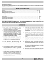
INDICE

2
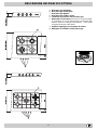
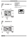
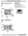
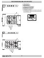
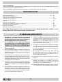
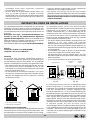
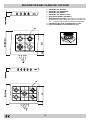
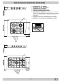
DESCRIZIONE DEI PIANI DI COTTURA
A Bruciatore gas Ausiliario
B Bruciatore gas Semirapido
C Bruciatore gas Rapido
D Bruciatore gas Tripla Corona
E Candela di accensione dei bruciatori gas
F Dispositivo di sicurezza (presente solo su alcuni model-
li) - Interviene in caso di spegnimento accidentale della
fiamma (trabocco di liquidi, correnti d'aria, ...) bloccando
l'erogazione del gas al bruciatore.
G Griglie di appoggio per recipienti di cottura
M Manopole di comando dei bruciatori gas
E
F
B
D
C
A

3
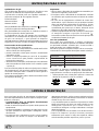
Bruciatori gas
Sono di diverse dimensioni e potenze. Scegliete quello più
adatto al diametro del recipiente da utilizzare.
Il bruciatore prescelto può essere regolato dalla manopola
"M" corrispondente come segue:
Rubinetto chiuso
Apertura massima
Apertura minima
Nelle vicinanze delle manopole i simboli indicano la
posizione sul piano del bruciatore relativo.
Inoltre, nelle vicinanze delle manopole i simboli indicano la
posizione sul piano del bruciatore relativo.
I bruciatori sono dotati di sicurezza contro fughe di gas a
termocoppia. Questo dispositivo provvede a bloccare l’uscita
del gas nel caso che la fiamma del bruciatore si spenga
durante il funzionamento.
Per accendere uno dei bruciatori procedere come segue:
• ruotare la manopola corrispondente in senso antiorario fino
al simbolo della fiamma grande;
• premere la manopola a fondo per azionare l’accensione
automatica del gas;
• mantenere la manopola premuta per circa 10 secondi con
la fiamma accesa per consentire il riscaldamento della
termocoppia di sicurezza;
• rilasciare la manopola, verificando che l’accensione sia
avvenuta in modo stabile. In caso contrario, ripetere
l’operazione.
Per avere la potenza minima ruotare la manopola verso il
simbolo della fiamma piccola. Sono possibili regolazioni
intermedie, posizionando la manopola tra il simbolo di fiamma
grande e quello della fiamma piccola.
Per spegnere il bruciatore ruotare la manopola in senso orario
fino alla posizione di chiuso " " .
Importante:
• Non azionare il dispositivo di accensione automatica per
più di 15 secondi consecutivi.
• In alcuni casi la difficoltà di accensione è dovuta ad
eventuale aria che può trovarsi all’interno del condotto del
gas.
• Nel caso di uno spegnimento accidentale della fiamma dei
bruciatori, il gas continua ad uscire per qualche istante prima
che intervenga il dispositivo di sicurezza. Chiudere la
manopola di comando e non ritentare l’accensione per
almeno 1 minuto, lasciando così dileguare il gas uscito
che può essere pericoloso.
• Quando l’apparecchiatura non è in funzione controllare che
le manopole siano in posizione di chiuso " ". Si consiglia
inoltre di chiudere il rubinetto principale del condotto di
alimentazione del gas.
Uso dei bruciatori
Per ottenere dai bruciatori il massimo rendimento si consiglia
adoperare solo pentole di diametro adatto al bruciatore
utilizzato, evitando che la fiamma fuoriesca dal fondo della
pentola (vedi tabella seguente).
Inoltre, quando un liquido inizia a bollire, si consiglia di ridurre
la fiamma quanto basta per mantenere l’ebollizione.
erotaicurB .mcnialotnepalledortemaiD
.A oirailisuA
41a6ad
.B odiparimeS
02a51ad
.C odipaR
62a12ad
.D anoroCalpirT
62a42ad
ISTRUZIONI PER L'USO
PULIZIA E MANUTENZIONE
Per una lunga durata dell’apparecchiatura è indispensabile
eseguire frequentemente una accurata pulizia generale,
tenendo conto che:
• L’apparecchiatura deve essere disinserita
elettricamente prima di iniziare la pulizia.
• Evitare di effettuare pulizie sulle parti ancora calde
dell’apparecchiatura.
• Le parti smaltate, cromate ed in vetro, vanno lavate con
acqua tiepida senza usare polveri abrasive e sostanze
corrosive che potrebbero rovinarle.
• Le parti in acciaio e soprattutto le zone con i simboli
serigrafati non devono essere pulite con diluenti o detersivi
abrasivi; utilizzare preferibilmente solo un panno morbido
inumidito con acqua tiepida e detersivo liquido per piatti
(passare il panno eseguendo il movimento nello stesso
senso della satinatura dell'acciaio).
Per lo sporco difficile è consentito l'uso di alcool denaturato.
L'acciaio inox può rimanere macchiato se rimane a contat-
to per lungo tempo con acqua fortemente calcarea o con
detergenti aggressivi (contenenti fosforo). Si consiglia quindi
di sciacquare sempre abbondantemente e di asciugare ac-
curatamente con una pelle di daino.
• Dopo la pulizia è possibile eseguire eventuali trattamenti
per risaltare la lucentezza dell' acciaio e prevenire eventuali
ingiallimenti; a tal proposito si consiglia l'utilizzo dell'apposita
"crema specifica per la cura dell'acciaio" in dotazione e
richiedibile presso i nostri Centri Assistenza.
• Evitare di lasciare sulle parti smaltate o verniciate dei liquidi
acidi (aceto, succo di limone, detergenti aggressivi, ecc.)
• Gli elementi mobili dei bruciatori del piano di cottura
Al fine di ottenere il massimo rendimento è utile ricordare
quanto segue:
Sui bruciatori possono essere utilizzati tutti i tipi di casse-
ruole. L’importante è che il fondo sia perfettamente piano.

4
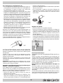
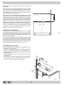
ventilazione singoli o collettivi ramificati conformi alla norma
UNI-CIG 7129. L’aria deve essere prelevata direttamente
dall’esterno, lontana da fonti di inquinamento. L’apertura di
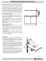
aerazione dovrà avere le seguenti caratteristiche (fig.2A):
• avere una sezione libera totale netta di passaggio di almeno
6 cm² per ogni kW di portata termica nominale
dell’apparecchio, con un minimo di 100 cm² (la portata
termica è rilevabile nella targhetta segnaletica);
• essere realizzata in modo che le bocche di apertura, sia
all’interno che all’esterno della parete, non possano venire
ostruite;
• essere protette ad esempio con griglie, reti metalliche, ecc.
in modo da non ridurre la sezione utile suindicata;
• essere situate ad una altezza prossima al livello del
pavimento.
Particolare A Locale Locale da
adiacente ventilare
A
Esempi di aperture di ventilazione Maggiorazione della fessura fra
per l’aria comburente porta e pavimento
fig. 2A fig. 2B
L’afflusso dell’aria può essere ottenuto anche da un locale
adiacente purché questo locale non sia una camera da letto
o un ambiente con pericolo di incendio quali rimesse, garage,
magazzini di materiale combustibile, ecc., e che sia ventilato
in conformità alla norma UNI-CIG 7129.
Il flusso dell’aria dal locale adiacente a quello da ventilare
deve avvenire liberamente attraverso aperture permanenti, di
sezione non minore di quella suindicata. Tali aperture potranno
anche essere ricavate maggiorando la fessura tra porta e
pavimento (fig.2B). Se per l’evacuazione dei prodotti della
combustione viene usato un elettroventilatore, l’apertura di
ventilazione dovrà essere aumentata in funzione della massima
portata d’aria dello stesso. L’elettroventilatore dovrà avere una
portata sufficiente a garantire un ricambio orario di aria pari a
3÷5 volte il volume del locale. Un utilizzo intensivo e prolungato
dell’apparecchio può necessitare di un’aerazione
supplementare, per esempio l’apertura di una finestra o
un’aerazione più efficace aumentando la potenza di
aspirazione dell’elettroventilatore se esso esiste. Gli
apparecchi sprovvisti di dispositivo di sicurezza per assenza
di fiamma possono essere utilizzati solo in ambienti con
ventilazione maggiorata con una sezione minima di apertura
di aerazione 200 cm² (D.M. 21-04-94).
Le istruzioni che seguono sono rivolte all’installatore qualificato
affinché compia le operazioni di installazione, regolazione e
manutenzione tecnica nel modo più corretto e secondo le
norme in vigore.
Importante: qualsiasi intervento di regolazione,
manutenzione, ecc. deve essere eseguito con il piano
elettricamente disinserito. Qualora sia necessario
mantenerlo collegato elettricamente, si dovranno prendere le
massime precauzioni.
I piani di cottura hanno le seguenti caratteristiche tecniche:
-Categoria II 2H3+ -Classe 1
Posizionamento
Questa apparecchiatura può essere installata e funzionare
solo in locali permanentemente ventilati secondo le
prescrizioni delle Norme UNI-CIG 7129 e 7131 in vigore.
Devono essere osservati i seguenti requisiti:
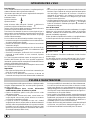
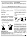
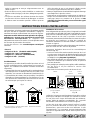
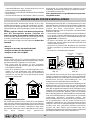
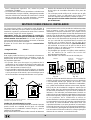
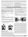
• L’apparecchio deve scaricare i prodotti della combustione
in una apposita cappa, che deve essere collegata ad un
camino, canna fumaria o direttamente all’esterno (fig.1).
• Se non è possibile l’applicazione di una cappa, è permesso
l’uso di un elettroventilatore, installato su finestra o su parete
affacciate all’esterno, da mettere in funzione
contemporaneamente all’apparecchio.
In camino o in canna fumaria ramificata Direttamente all’esterno
(riservata agli apparecchi di cottura)
Ventilazione ambiente cucina
É necessario che nell’ambiente dove viene installato
l’apparecchio possa affluire una quantità di aria pari a quanta
ne viene richiesta dalla regolare combustione del gas e dalla
ventilazione dell’ambiente. L’afflusso naturale dell’aria deve
avvenire attraverso aperture permanenti praticate su pareti
del locale che danno verso l’esterno, oppure da condotti di
ISTRUZIONI PER L'INSTALLATORE
fig.1
vanno lavati frequentemente con acqua calda e detersivo
avendo cura di eliminare le eventuali incrostazioni.
Controllare che le fessure di uscita del gas non siano
otturate. Asciugarli accuratamente prima di riutilizzarli.
• Eseguire frequentemente la pulizia della parte terminale
delle candelette di accensione automatica del piano di
cottura.
Ingrassaggio dei rubinetti
Con il tempo può verificarsi il caso di un rubinetto che si
blocchi o presenti difficoltà nella rotazione, pertanto sarà ne-
cessario provvedere alla pulizia interna e alla sostituzione del
grasso. Questa operazione deve essere effettuata da un
tecnico autorizzato dal costruttore.

5
I gas di petrolio liquefatti, più pesanti dell’aria, ristagnano
verso il basso. Quindi i locali contenenti bombole di GPL
devono avere delle aperture verso l’esterno al livello del
pavimento, così da permettere l’evacuazione dal basso delle
eventuali fughe di gas. Inoltre non depositare bombole di
GPL (anche vuote) in locali a livello più basso del suolo; è
opportuno tenere nel locale solo la bombola in utilizzo,
collegata lontana da sorgenti di calore che possano portarla
ad una temperatura superiore a 50 °C.
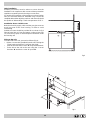
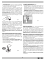
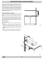
Installazione dei piani di cottura
È necessario prendere le opportune precauzioni al fine di
assicurare una installazione rispondente alle norme
antinfortunistiche in vigore (CEI-UNI-CIG) per l’allacciamento
elettrico e gas.
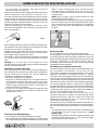
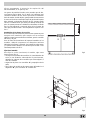
Per il buon funzionamento dei piani di cottura da appoggio
installati nei mobili devono essere rispettate le distanze
minime indicate in fig.3. Inoltre, le superfici adiacenti e la
parete posteriore devono essere idonee per resistere ad una
sovratemperatura di 65°C.
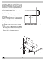
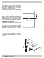
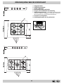
Fissaggio al mobile
Per il fissaggio dei piani eseguire le seguenti operazioni
(fig. 4);
• avvitare al mobile 2 viti "A" (in dotazione) con le distanze
dalla parete posteriore indicate in figura, lasciando le teste
delle viti sporgenti 1,5 mm dal legno;
• agganciare il piano alle 2 viti "A" e spingerlo all'indietro;
• fissarlo al mobile nella parte posteriore usando le 2
squadrette "B" e le quattro viti "C" in dotazione.
fig.4
fig.3
1.5 mm1.5
mm
A
B
C
XmmX
mm
XmmX
mm

6
• rimontare le parti eseguendo all’inverso le operazioni.
• al termine dell’operazione, sostituite la vecchia etichetta
taratura con quella corrispondente al nuovo gas d’utilizzo,
reperibile presso i Nostri Centri Assistenza Tecnica.
A
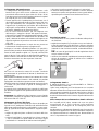
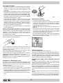
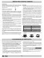
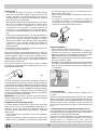
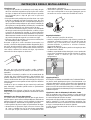
Regolazione minimi
• Con il bruciatore acceso, portare il rubinetto sulla posizio-
ne di minimo;
• togliere la manopola (fig.7) ed agire con un cacciavite sul-
la vite di regolazione posta all’interno o di fianco all’astina
del rubinetto fino ad ottenere una piccola fiamma regolare
(svitando la vite il minimo aumenta, avvitandola diminui-
sce).
N.B.: nel caso dei gas liquidi, la vite di regolazione dovrà
essere avvitata a fondo.
• verificare che ruotando rapidamente la manopola dalla po-
sizione di massimo a quella di minimo non si abbiano
spegnimenti dei bruciatori.
fig.7
Collegamento elettrico
È OBBLIGATORIO IL COLLEGAMENTO A TERRA
DELL’APPARECCHIATURA.
I piani sono predisposti per il funzionamento con corrente
alternata alla tensione e frequenza di alimentazione indicate
sulla targhetta caratteristiche (posta sotto il piano o alla fine
del libretto istruzioni). Accertarsi che il valore locale della
tensione di alimentazione sia lo stesso di quello indicato sulla
targhetta.
Allacciamento del cavo alimentazione elettrico alla rete
Per i modelli privi di spina, montare sul cavo una spina
normalizzata per il carico indicato sulla targhetta
caratteristiche e collegarla ad una adeguata presa di
corrente.
Desiderando un collegamento diretto alla rete è necessario
interporre tra l’apparecchio e la rete un interruttore onnipolare
con apertura minima tra i contatti di 3 mm, dimensionato al
carico e rispondente alle norme in vigore.
Collegamento alimentazione gas
• Il collegamento dell’apparecchio alla tubazione o alla
bombola del gas deve essere effettuato secondo le
prescrizioni delle norme in vigore (UNI-CIG 7129 e 7131)
solo dopo essersi accertati che l’apparecchiatura è regolata
per il tipo di gas con cui sarà alimentata.
• Questo apparecchio è predisposto per funzionare con il
gas indicato nell’etichetta posta sul piano stesso. Nel caso
che il gas distribuito non corrisponda a quello per cui
l’apparecchio è predisposto, procedere alla sostituzione
degli ugelli corrispondenti (in dotazione), consultando il
paragrafo “Adattamento ai diversi tipi di gas”.
• Per un sicuro funzionamento, per un adeguato uso
dell’energia e maggiore durata dell’apparecchiatura,
assicurarsi che la pressione di alimentazione rispetti i valori
indicati nella tabella 1 “Caratteristiche dei bruciatori ed
ugelli”, altrimenti installare sulla tubazione di ingresso un
apposito regolatore di pressione secondo la norma UNI-
CIG 7430.
• Effettuare Il collegamento in modo da non provocare
sollecitazioni di nessun genere sull’apparecchio.
Collegare al raccordo orientabile (filettato ½"G maschio),
posto nel lato posteriore destro dell’apparecchio (fig.5), per
mezzo di tubo metallico rigido e a raccordi conformi alla
norma UNI-CIG 7129, oppure con tubo flessibile metallico a
parete continua conforme alla norma UNI-CIG 9891, la cui
massima estensione non deve superare i 2000 mm.
Nel caso sia necessario ruotare il raccordo, sostituire
tassativamente la guarnizione di tenuta (in dotazione con
l’apparecchio).
Ad installazione ultimata accertarsi che la tenuta del circuito
gas, delle connessioni interne e dei rubinetti sia perfetta
impiegando una soluzione saponosa (mai una fiamma).
Verificare inoltre che il tubo di collegamento non possa venire
a contatto con parti mobili in grado di danneggiarlo o
schiacciarlo.
Accertarsi che la conduttura del gas naturale sia sufficiente
per alimentare l’apparecchio quando tutti i bruciatori sono in
funzione.
Importante: Per effettuare l’allacciamento con gas liquido
(in bombola), interporre un regolatore di pressione conforme
alla norma UNI-CIG 7432-75.
Adattamento ai diversi tipi di gas
Per adattare il piano ad un tipo di gas diverso da quello per
il quale esso è predisposto (indicato sulla etichetta fissata
nella parte superiore del piano o sull'imballo), occorre sosti-
tuire gli ugelli dei bruciatori effettuando le seguenti opera-
zioni:
• togliere le griglie del piano e sfilare i bruciatori dalle loro
sedi;
• svitare gli ugelli (fig.6), servendosi di una chiave a tubo da
7 mm. e sostituirli con quelli adatti al nuovo tipo di gas
(vedi tabella 1 “Caratteristiche dei bruciatori ed ugelli”).
fig.6
fig.5

7
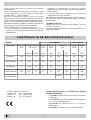
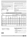
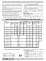
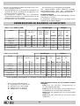
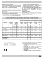
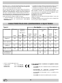
CARATTERISTICHE DEI BRUCIATORI ED UGELLI
• l’impianto di alimentazione sia munito di efficace
collegamento a terra secondo le norme e le disposizioni di
legge in vigore;
• la presa o l’interruttore onnipolare siano facilmente
raggiungibili con il piano installato.
DECLINIAMO OGNI RESPONSABILITÀ NEL CASO LE
NORME ANTINFORTUNISTICHE NON VENGANO
RISPETTATE.
Sostituzione del cavo
Utilizzare un cavo in gomma del tipo H05RR-F con una
sezione 3 x 0.75 mm²
Il conduttore giallo-verde dovrà essere più lungo di 2÷3 cm.
degli altri conduttori.
Il filo di terra giallo-verde non deve essere interrotto
dall’interruttore.
Il cavo di alimentazione deve essere posizionato in modo
che non raggiunga in nessun punto una temperatura
superiore di 50 °C a quella ambiente.
Nel caso di installazione sopra un forno da incasso
l’allacciamento elettrico del piano e quello del forno devono
essere realizzati separatamente, sia per ragioni di sicurezza
elettrica, sia per facilitare l’eventuale estraibilità del forno.
Non utilizzare riduzioni, adattatori o derivatori in quanto essi
potrebbero provocare riscaldamenti o bruciature.
Prima di effettuare l’allacciamento accertarsi che:
• la valvola limitatrice e l’impianto domestico possano
sopportare il carico dell’apparecchiatura (vedi targhetta
caratteristiche);
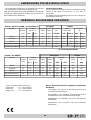
* A 15°C e 1013 mbar-gas secco
Propano G31 H.s. = 50,37 MJ/kg
Butano G30 H.s. = 49,47 MJ/kg
Metano G20 H.s. = 37,78 MJ/m
3
Questa apparecchiatura è conforme alle seguenti
Direttive Comunitarie:
- 73/23/CEE del 19/02/73 (Bassa Tensione) e successive
modificazioni;
- 89/336/CEE del 03/05/89 (Compatibilità Elettromagneti-
ca) e successive modificazioni;
- 90/396/CEE del 29/06/90 (Gas) e successive
modificazioni;
- 93/68/CEE del 22/07/93 e successive modificazioni.
Tabella 1 Gas liquido Gas naturale
Bruciatore Diametro
(mm)
Potenza termica
kW (H.s.*)
By-pass
1/100
(mm)
Ugello
1/100
(mm)
Portata *
g/h
Ugello
1/100
(mm)
Portata *
l/h
Nomin. Ridot. G30 G31 G20
Rapido C 100 3.00 0.7 40 86 218 214 116 286
Semirapido B 75 1.65 0.4 30 64 120 118 96 157
Ausiliario A 55 1.00 0.3 27 50 73 71 71 95
Tripla corona D 130 3.25 1.3 57 91 236 232 124 309
Pressione di
alimentazione
28-30 37 20

8
1. This appliance has been designed for private, non-
professional use in normal dwellings.
2. Carefully read the recommendations in this
instruction booklet, as they give important advice
regarding safe installation, use and maintenance.
Keep this booklet in a safe place for further reference
when required.
3. After removing the packaging, check that the appliance
is intact. If in doubt, do not use the appliance and contact
professionally qualified personnel.
4. All installation and adjustment operations should be
carried out by qualified engineers in accordance with
current regulations. Specific directions are given in the
“installation instructions” paragraph.
5. Periodically check the condition of the gas connection
pipe and have it replaced by a qualified technician as
soon as it shows any signs of wear or anomaly.
6. Under no circumstances should the user replace the
power supply cable or the gas connection pipe of this
appliance. In the event of damage or the necessity for
replacement, only contact an authorised service centre.
RECOMMENDATIONS
7. Before connecting the appliance, make sure that the data
on the rating plate (situated on the bottom part of the
appliance and on the last page of the booklet) correspond
to those of the mains electricity and gas supplies.
8. Check that the capacity of the electrical system and the
power outlets are suitable for the maximum power of
the appliance, indicated on the rating plate. If in doubt,
consult a professionally qualified technician.
9. Do not leave the appliance plugged in if it is not in use.
Switch off the main switch and gas supply when you are
not using the hob.
10. The gas burners and pan supports remain heated for a
long time after use. Take care not to touch them.
11. To avoid accidental spillage do not use cookware with
uneven or deformed bottoms on the burner.
12. Never use flammable liquids such as alcohol or gasoline,
etc. near the appliance when it is in use.
Congratulations!
You have just purchased an electrical household appliance that has been made using advanced technology and quality
materials. As time passes, you will appreciate its practicality and safety, which are constant features of our production.
CONTENTS
Recommendations.........................................................................................................................................page 8
Hob description.............................................................…………………....………………..............….................." 9
Instructions for use - gas burners...........................…………………...……………..…........................................." 10
Cleaning and maintenance...........................................................…….......………………………........................." 10-11
Instructions for the installer.............................................…………..………………………....................................."11
Position..................................................................................…………………………………………....................."11
Hobs installation..................................................................................…………………………………………........" 12
Gas supply connection........................................................................…………………………………………........" 13
Adaptation to a different type of gas.....................................................………………………………..………........." 13
Electrical connection.............................................................................……………………………………….........." 13-14
Burners and nozzles specifications.................................................………………………………………................" 14
THESE INSTRUCTIONS ARE ONLY VALID FOR THE COUNTRIES OF DESTINATION WHOSE SYMBOLS ARE SHOWN
IN THE BOOKLET AND ON THE APPLIANCE RATING PLATE.

9
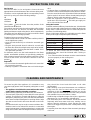
HOB DESCRIPTION
A Auxiliary gas burner
B Semi-rapid gas burner
C Rapid gas-burner
D Triple ring gas burner
G Pan supports
E Ignitor for gas burners
F Safety device - Activates if the flame accidentally goes
out (spills, drafts, etc.), interrupting the delivery of gas to
the burner.
M Control knobs for gas burners
E
F
B
D
C
A

10
Gas burners
The burners differ in size and power. Choose the most
appropriate one for the diameter of the cookware being used.
The burner can be regulated with the corresponding control
knob "M" by using one of the following settings:
Off
High flame
Low flame
The symbols near the knobs show the position of the
relative burner on the hob.
The symbols near the knobs show the position of the relative
burner on the hob. The burners are fitted with automatic
ignition and thermocouple safety device, which automatically
cuts off the gas from the burner in a few seconds if the flame
accidentally goes out during operation.
To ignite a burner proceed as follows:
• turn the relative knob counter-clockwise until the pointer is
on the high-flame symbol;
• press the knob down fully to activate the automatic gas
ignition;
• keep the knob pressed down for about 10 seconds with
the flame lit to allow the safety thermocouple to be heated;
• release the knob, checking that the flame is stable. If it is
not, repeat the operation.
For minimum power, turn the knob towards the low flame
symbol. Intermediate positions are possible by putting the
knob anywhere between the high and the low flame symbol.
To turn off the burner, turn the knob clockwise to the off
position " " .
Important:
• Do not activate the automatic ignition device for more than
15 consecutive seconds.
• Difficulty in ignition is sometimes due to air inside the gas
duct.
• If a burner flame accidentally goes out, the gas continues
to exit for a few moments before the safety device activates.
Turn the control knob to the off position and do not attempt
ignition again for at least 1 minute, thereby letting the gas
disperse, which could otherwise be a danger.
• When the equipment is not in operation, check that the
knobs are in the off position " ". The main gas supply cut-
off cock should also be closed.
Using the burners
To obtain maximum efficiency from the burners, it is advisable
to use only pans with a diameter that is suitable for the burner
being used, so that the flame does not extend beyond the
pan base (see following table).
When a liquid starts boiling, it is advisable to turn the flame
down just enough to keep the liquid simmering.
renruB .mcninapehtforetemaiD
.A yrailixuA
41ot6morf
.B dipar-imeS
02ot51morf
.C dipaR
03ot12morf
.D gnirelpirT
03ot42morf
INSTRUCTIONS FOR USE
CLEANING AND MAINTENANCE
To ensure long life of the appliance, it is essential to carry
out a thorough general clean frequently, taking into account
that:
• The appliance should be disconnected from the mains
supply before starting cleaning operations.
• Avoid cleaning appliance parts when they are still warm.
• The steel parts, especially in areas with the screen-printed
symbols, should not be cleaned with diluents or abrasive
detergents; preferably use just a soft cloth moistened with
warm water and liquid detergent for washing dishes (
wipe
the cloth over the steel in the same direction as the satin-
finish
).
Denatured alcohol may be used to remove stubborn dirt.
Stainless steel can be stained if it remains in contact with
agressive detergents (containing phosphorus) or water with
a high lime content. After washing the stainless steel parts
they should be rinsed and dried with a soft cloth
(washleather).
• After cleaning, some special treatments are available to
bring back the shine to steel and to prevent it from
yellowing; for this purpose, we recommend you use the
specific “
special cream detergent for steel care
” provided
and available from our Assistance Centres.
• Avoid leaving acid liquids (vinegar, lemon juice, aggressive
detergents, etc.) on enamelled or painted parts.
• The removable parts of the burners should be washed
frequently with warm water and soap, making sure to
remove caked-on substance. Check that the gas outlet
slits are not clogged. Dry the burners carefully before using
them again.
• Frequently clean the end part of the automatic glow plugs
of the hob.
To obtain the best results with the cooktop, several
fundamental rules should be followed while cooking or
preparing food.
• Use cookware with a flat bottom to make certain that the
pot sets properly on the cooking area.

11
characteristics (fig.2A):
· total free cross section of passage of at least 6 cm² for
every kW of rated heating capacity of the appliance, with
a minimum of 100 cm² (the heating capacity is indicated
on the rating plate);
· it must be made in such a way that the aperture, both on
the inside and outside of the wall, cannot be obstructed;
· it must be protected, e.g. with grills, wire mesh, etc. in
such a way that the above-mentioned free section is not
reduced;
· it must be situated as near to floor level as possible.
Detail A Adjacent Room to be
room ventilated
A
Examples of ventilation holes Enlarging the ventilation slot
for comburant air between window and floor
Fig. 2A Fig. 2B
The air inflow may also be obtained from an adjoining room,
provided the latter is not a bedroom or a room where there
is a risk of fire, such as garages, mews, fuel stores, etc. and
is ventilated in compliance with the standards in force.
Air from the adjoining room to the one to be ventilated may
be made to freely pass through permanent apertures with a
cross section at least equal to that indicated above. These
apertures may also be obtained by increasing the gap
between the door and the floor (fig.2B).
If an electric fan is used for extracting the combustion
products, the ventilation aperture must be increased in
relation to its maximum performance. The electric fan should
have a sufficient capacity to guarantee an hourly exchange
of air equal to 3-5 times the volume of the kitchen.
Prolonged, intensive use of the appliance may require extra
ventilation, e.g. an open window or a more efficient ventilation
system by increasing the extraction power of the electric fan
if installed.
Liquid petroleum gas descends towards the floor as it is
heavier than air. Apertures in the outside walls in rooms
containing LPG cylinders should therefore be at floor level,
in order to allow any gas from leaks to be expelled. Do not
store LPG cylinders (even when empty) in basements/rooms
below ground level; it is advisable to keep only the cylinder
in use in the room at any one time and connected far from
heat sources which could raise its temperature to above 50
°C.
The following instructions are provided for qualified installers
so that they may accomplish installation, adjustment and
technical maintenance operations correctly and in
compliance with current regulations and standards.
Important: the hob should be disconnected from the
mains electricity supply before any adjustment,
maintenance, etc. is carried out. Maximum caution should
be used whenever it is necessary to keep the appliance
connected to the electricity supply.
The hobs have the following technical characteristics:
-Category II 2H3+ -Class 1
Positioning
This appliance may only be installed and operated in
permanently ventilated rooms in compliance with provisions
laid down by current regulations and standards. The following
requirements must be observed:
• The appliance must discharge combustion products into a
special hood, which must be connected to a chimney, flue
pipe or directly to the outside (fig.1).
• If it is impossible to fit a hood, the use of an electric fan is
permitted, either installed on a window or on an external
wall, which must be switched on at the same time as the
appliance.
In a chimney stack or branched flue Directly to the outside
(exclusively for cooking appliances)
Kitchen ventilation
The air flow into the room where the appliance is installed
must equal the quantity of air that is required for regular
combustion of the gas and for ventilating the same room.
Air must be taken in naturally through permanent apertures
made in the outside walls of the room or through single or
branching collective ventilation ducts in compliance with the
standards in force.
The air must be taken directly from the outside, from an area
far from sources of pollution.
The ventilation aperture must have the following
INSTRUCTIONS FOR THE INSTALLER
fig.1
Greasing the taps
As time passes, a tap may lock or become difficult to turn. In
this case it will be necessary to clean inside and replace the
grease.
This procedure must be performed by a technician
authorized by the manufacturer.

12
Hobs installation
Suitable precautions must be taken to ensure that the
installation is in compliance with current accident-prevention
regulations regarding electrical and gas connections.
For trouble-free operation of the appliance set into kitchen
units, the minimum distances indicated in fig.3 should be
complied with and the adjoining surfaces and rear wall should
be capable of withstanding a surface temperature of 65 °C.
Installation above a built-in oven
Both the electricity supply cable and the gas pipe must not
touch hot parts of the oven housing, in order to avoid
overheating.
Suitable air vents should be provided for as shown in fig.3
(inlet at least 200 cm² from the bottom, outlet at least 120
cm² from the top part) to allow adequate ventilation inside
the housing unit.
Fixing to the unit
To fix the hob to the unit, proceed as follows (fig.4);
• tighten 2 screws “A” (provided) into the unit, leaving the
screw heads projecting 1.5 mm from the wood;
• hook the hob onto the 2 screws “A” and push backwards;
• fix the hob to the unit at the rear using the 2 corner
brackets “B” and the 4 screws “C” provided.
fig.3
fig.4
1.5 mm1.5
mm
A
B
C
XmmX
mm
XmmX
mm

13
A
Adjusting the low flame
· Put the tap to the low flame position;
· Remove the tap knob and turn the adjusting screw, situated
inside or to the side of the tap stem (fig.7), using a
screwdriver (loosening the screw increases the height of
the flame, tightening decreases it).
note: the adjusting screw must be fully screwed down for
liquid gas.
· Having obtained the low flame setting required and with
the burner lit, abruptly change the position of the knob
several times from minimum to maximum and vice versa
and check that the flame does not go out.
• On completing the operation, replace the old rating label
with the one showing the new type of gas; the sticker is
available from our Service Centres.
fig.7
Electrical connection
THE APPLIANCE MUST BE EARTHED
The hobs are designed to work with alternating current at
the supply voltage and frequency indicated on the rating plate
(situated under the hob or at the end of the instruction
booklet). Make sure that the local supply voltage corresponds
to the voltage indicated on the rating plate.
Connecting the supply cable to the mains electricity
supply
For models supplied without a plug, fit a standard plug,
suitable for the load indicated on the rating plate, onto the
cable and connect to a suitable socket.
To connect directly to the mains supply, a double-pole switch
with a contact separation of at least 3 mm suitable for the
load and complying with current standards and regulations,
must be fitted between the appliance and the mains supply
outlet.
The yellow-green earth wire must not be interrupted by the
switch.
The supply cable must be in such a position that no part of it
can reach a temperature of 50 °C above room temperature.
For installation above a built-under oven, the hob and the
Gas supply connection
• Check that the appliance is set for the type of gas available
and then connect it to the mains gas piping or the gas
cylinder in compliance with current regulations and
standards.
• This appliance is designed and set to work with the gas
indicated on the label situated on the actual hob. If the gas
supply is other than the type for which the appliance has
been set, proceed with replacing the corresponding nozzles
(provided), following instructions given in the paragraph
“Adaptation to different types of gas”.
• For trouble-free operation, suitable use of energy and
longer life of the appliance, make sure that the supply
pressure complies with the values indicated in the table 1
"burners and nozzles specifications, otherwise install a
special pressure regulator on the supply pipe in compliance
with current standards and regulations.
• Connect in such a way that the appliance is subjected to
no strain whatsoever.
Either a rigid metal pipe with fittings in compliance with the
standards in force must be used for connecting to the nipple
union (threaded ½"G male fitting) situated at the rear of the
appliance to the right (fig.5), or flexible steel pipe in
compliance with the standards in force, which must not
exceed 2000 mm in length.
Should it be necessary to turn the fitting, the gasket (supplied
with the appliance) must be replaced.
Upon completion of installation, check the gas circuit, the
internal connections and the taps for leaks using a soapy
solution (never a flame).
Also check that the connecting pipe cannot come into contact
with moving parts which could damage or crush it.
Make sure that the natural gas pipe is adequate for a sufficient
supply to the appliance when all the burners are lit
Important: A pressure regulator, in compliance with the
standards in force, must be inserted when connecting to a
liquid gas supply (in a cylinder).
Adaptation to a different type of gas
If the hob is to be converted for use with a type of gas other
than that for which it was set in the factory (indicated on the
label to be found on the hob), the burner nozzles should be
replaced as follows:
• Remove the pan supports and the burners.
• Unscrew the nozzles “A” (fig.6) using a 7 mm socket
wrench and replace them with the ones which have a
diameter suitable for the type of gas to be used, according
to the table 1 "burners and nozzles specifications).
• Reassemble the parts following the instructions in reverse
order.
fig.6
fig.5

14
BURNERS AND NOZZLES SPECIFICATIONS
As the colours of the wires in the mains lead may not
correspond with the coloured markings identifying the
terminals in your plug, proceed as follows:
Connect the Green & Yellow wire to terminal marked “E” or
or coloured Green or Green & Yellow.
Connect the Brown wire to the terminal marked “L” or
coloured Red.
Connect the Blue wire to the terminal marked “N” or coloured
Black.
FAILURE TO OBSERVE THE ACCIDENT-PREVENTION
REGULATIONS RELIEVES THE MANUFACTURER OF ALL
LIABILITY.
Replacing the cable
Use a rubber cable of the type H05RR-F with a suitable cross
section 3 x 0.75 mm².
The yellow-green earth wire must be 2-3 cm longer than the
other wires.
oven must be connected separately to the electricity supply
both for safety reasons and for easy removal of the oven if
necessary.
Do not use adapters or shunts as they could cause heating
or burning.
Before connecting to the power supply, make sure that:
• the limiter valve and the domestic system can withstand
the load from the appliance (see rating plate);
• the supply system is efficiently earthed according to
standards and laws in force;
• the socket or double-pole switch are easily accessible when
the appliance is installed.
Important: the wires in the mains lead are coloured in
accordance with the following code:
Green & Yellow - Earth
Blue - Neutral
Brown - Live
This appliance conforms with the following European
Economic Community directives:
- 73/23/EEC of 19/02/73 (Low Voltage) and subsequent
modifications;
- 89/336/EEC of 03/05/89 (Electromagnetic Compatibility)
and subsequent modifications;
- 90/396/EEC of 29/06/90 (Gas) and subsequent
modifications;
- 93/68/EEC of 22/07/93 and subsequent modifications.
* At 15°C and 1013 mbar-dry gas
Propane G31 H.s. = 50,37 MJ/kg
Butane G30 H.s. = 49,47 MJ/kg
Methane G20 H.s. = 37,78 MJ/m
3
Table 1 Liquid gas Natural gas
Burner Diameter
(mm)
Thermal power
kW (H.s.*)
By-pass
1/100
(mm)
Injector
1/100
(mm)
Flow *
g/h
Injector
1/100
(mm)
Flow*
l/h
Nomin. Reduc. G30 G31 G20
Rapid C 100 3.00 0.7 40 86 218 214 116 286
Semi-rapid B 75 1.65 0.4 30 64 120 118 96 157
Auxiliary A 55 1.00 0.3 27 50 73 71 71 95
Triple ring D 130 3.25 1.3 57 91 236 232 124 309
Supply pressure 30 37 20

15
CH
1. Cet appareil a été conçu pour un usage familial de
type non-professionnel à l’intérieur d’une habitation
normale.
2. Lisez attentivement les avertissements contenus
dans ce livret, ils vous fourniront des
renseignements importants concernant la sécurité
d’installation, d’emploi et d’entretien de votre four.
Gardez-le ensuite à portée de la main afin de pouvoir
le consulter en cas de besoin.
3. Après avoir enlevé l’emballage, assurez-vous que
l’appareil soit intact. En cas de doute, n’utilisez pas le
four et adressez-vous à un personnel qualifié.
4. Toutes les opérations relatives à l’installation et au
réglage du four doivent être effectuées par un personnel
qualifié, conformément aux normes en vigueur. Les
instructions techniques sont décrites dans la partie
réservée à l’installateur.
5. Vérifiez périodiquement le bon état du tuyau de
raccordement gaz et adressez-vous à un personnel
qualifié pour le faire remplacer dès qu’il présente une
anomalie.
6. Le câble d’alimentation et le tuyau de raccordement gaz
de cet appareil ne peuvent en aucun cas être remplacés
par l’utilisateur. En cas d’endommagement et d’éventuel
remplacement, faites appel exclusivement à un centre
de service après-vente agréé.
AVERTISSEMENTS
7. Avant de brancher l’appareil, assurez-vous que
l’alimentation électrique et du gaz du réseau
correspondent bien aux données indiquées sur la
plaquette signalétique (apposée sur la partie inférieure
de l’appareil et à la dernière page du livret).
8. Vérifiez que la puissance électrique de l’installation et
des prises de courant soit appropriée à la puissance
maximale de l’appareil indiquée sur la plaquette
signalétique. En cas de doute, faites appel à un
électricien qualifié.
9. Fermez la soupape du gaz et éteignez l’interrupteur
général de l’appareil lorsque vous ne l’utilisez pas
pendant longtemps.
10. Les brûleurs restent chaudes pendant longtemps après
l'usage. Faites attention et ne les touchez pas.
11. Ne pas déposer de casseroles instables ou déformées
sur les brûleurs afin d’éviter tout renversement
accidentel.
12. Ne pas utiliser de solutions inflammables (alcool,
essence..) à proximité de l’appareil lorsqu’il est en
marche.
Félicitations!
Vous venez d’acheter un électroménager construit avec des matériaux de qualité et des processus technologiques avancés.
En l’utilisant, vous aurez l’occasion d’en apprécier la fonctionnalité et la sécurité, caractéristiques constantes de notre
production.
TABLE DE MATIÈRES
Avertissements........................................................................................................…………………..........Page 15
Description du plan de cuisson...................................………………………......……………………...…..........“ 16
Instructions pour l'utilisation - brûleurs gaz......………………………….........................…………………...…..“ 17
Nettoyage et entretien..................................................................……………………………………................“ 17-18
Instructions pour l'installation.........................................…………..……………………….…...........................“ 18
Positionnement.........................................................……………………………………...................................“ 18
Installation des plans de cuisson.........................................................………………………………………....“ 19
Raccordement à la canalisation du gaz..............................................……………………………………….....“ 20
Adaptation a un différent type de gaz...................................................…………………………………….......“ 20
Réglage des minima.............................................................................……………………………..……........“ 20
Branchement électrique........................................................................…………………………………..........“ 20-21
Caractéristiques des brûleurs et des injecteurs..............................…………………………………….............“ 21
CES INSTRUCTIONS NE SONT VALABLES QUE POUR LES PAYS DE DESTINATION DONT LES SYMBOLES SONT
REPRODUITS SUR LE MODE D’EMPLOI ET SUR LA PLAQUETTE SIGNALÉTIQUE DE L’APPAREIL.

16
CH
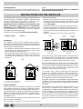
DESCRIPTION DU PLAN DE CUISSON
A Brûleur gaz Auxiliaire
B Brûleur gaz Semi rapide
C Brûleur gaz Rapide
D Brûleur gaz Triple couronne
G Grilles support de casseroles
M Manettes de commande des brûleurs gaz
E Bougie d'allumage des brûleurs gaz
F Dispositif de sécurité - Intervient en cas d'extinction
accidentelle de la flamme (débordement de liquides,
courants d'air, ...) en interrompant automatiquement
l'arrivée de gaz.
E
F
B
D
C
A

17
CH
Brûleurs gaz
Ils ont des dimensions et des puissances différentes.
Choisissez-en un en fonction du diamètre de la casserole
utilisée.
Pour le réglage du brûleur choisi, servez-vous de la manet-
te correspondante "M", comme suit:
Robinet fermé
Ouverture maximale
Ouverture minimale
À côté des manettes figurent les symboles indiquant la
position du brûleur correspondant sur le plan de cuisson.
À côté des manettes figurent les symboles indiquant la
position du brûleur correspondant sur le plan de cuisson.
Le plan de cuisson est muni d'un dispositif de sécurité à
thermocouple contre les fuites de gaz sur les brûleurs, celui-
ci permet de couper automatiquement la sortie du gaz du
brûleur en quelques secondes si la flamme s'éteint
accindentellement pendant le fonctionnement
Allumage des brûleurs
Pour allumer un des brûleurs:
• tournez la manette correspondante dans le sens inverse
à celui des aiguilles d’une montre afin de placer l’index en
face du symbole de la grande flamme;
• poussez à fond la manette afin d’actionner l’allumage
automatique du gaz;
• maintenez la manette poussée pendant 10 secondes
environ avec la flamme allumée afin de permettre le
réchauffement du thermocouple de sécurité;
• relâchez la manette et assurez-vous que l’allumage s’est
bien fait de manière stable. Dans le cas contraire,
renouvelez l’opération.
Tournez la manette vers le symbole de la petite flamme pour
obtenir la puissance minimale. Il est possible de régler la
hauteur de la flamme en variant la position de la manette
entre les positions “grande flamme” et “petite flamme”.
Pour éteindre le brûleur, tournez la manette dans le sens
des aiguilles d’une montre et placez l’index en face de la
position de fermeture " " .
Important:
• Ne pas actionner le dispositif d’allumage automatique
pendant plus de 15 secondes consécutives.
• Dans certains cas, les problèmes d’allumage peuvent être
dûs à la présence d’air à l’intérieur de la canalisation du
gaz.
• Si la flamme d’un des brûleurs s’éteint accidentellement,
le gaz continue à s’échapper pendant quelques instants
avant l’intervention du dispositif de sécurité. Fermez la
manette de commande et attendez au moins 1 minute
avant de renouveler l’allumage afin de permettre la
dissipation du gaz sorti qui peut être dangereux.
• Lorsque le plan de cuisson n’est pas utilisé, contrôlez que
les manettes soient sur la position de fermeture " ". Il est
conseillé, en outre, de fermer le robinet de barrage principal
de la canalisation d’alimentation du gaz.
Utilisation des brûleurs
Afin d’obtenir un rendement optimal des brûleurs, choisissez
un brûleur approprié au diamètre du récipient à utiliser.
Réglez la couronne de flammes pour qu’elle ne déborde pas
le pourtour du récipient (voir tableau ci-après).
Il est conseillé, en outre, de réduire la flamme dès qu’un
liquide commence à bouillir, de maniére à maintenir
l’ébullition.
ruelûrB .mcnetneipicérudertèmaiD
.A eriailixuA
41à6ed
B edipar-imeS.
02à51ed
.C edipaR
03à12ed
.D ennoruocelpirT
03à42ed
INSTRUCTIONS POUR L'UTILISATION
NETTOYAGE ET ENTRETIEN
Afin de garantir une longue durée de votre plan de cuisson,
nous vous conseillons d’exécuter fréquemment un minutieux
nettoyage général en respectant les règles suivantes:
• Débranchez l’alimentation électrique du plan de
cuisson avant de procéder à toute opération de nettoyage.
• Evitez d’effectuer les opérations de nettoyage quand des
parties du plan de cuisson sont encore chaudes.
• Les parties émaillées, chromées et en verre doivent être
lavés à l'eau tiède en évitant toute utilisation de poudres
abrasives ou de produits corrosifs qui pourraient les
endommager.
• Les parties en acier et surtout les zones sérigraphiées ne
doivent pas être nettoyées avec des diluants ou des
détergents abrasifs; se servir préférablement d’un chiffon
souple, humidifié avec de l’eau tiède et un produit détergent
liquide pour vaisselle (passer le chiffon dans le sens du
satinage de l’acier).
• Pour faire ressortir le brillant de l’acier et prévenir au besoin
son jaunissement, traitez-le avec un produit spécial après
l’avoir soigneusement nettoyé ; à ce propos, nous vous
conseillons d’utiliser la “crème spéciale pour l’entretien de
l’acier” que nous fournissons avec notre article et disponible
auprès de nos Services après-vente agréés.
• Pour nettoyer la saleté plus tenace, l’usage d’alcool
dénaturé est consenti.
• L'acier inox peut rester taché s'il est en contact prolongé
avec de l'eau calcaire ou un détergent agressif.
Il est donc nécessaire de rinçer abondamment la surface
Pour obtenir les meilleures performances de votre plan de
cuisson, il est important de suivre certaines règles
fondamentales pendant la cuisson et pendant la préparation
des aliments.
• Utilisez des casseroles à fond plat pour qu’elles adhèrent
parfaitement à la zone de chauffe

18
CH
Ventilation de la cuisine
Il est indispensable que dans la pièce où l’appareil est installé
puisse affluer une quantité d’air égale à la quantité nécessaire
pour la bonne combustion du gaz et l’aération de la pièce.
L’afflux naturel de l’air doit se produire à travers des
ouvertures permanentes réalisées dans les murs de la pièce
qui donnent vers l’extérieur, ou bien des conduits de
ventilation individuels ou collectifs ramifiés, conformes aux
normes en vigueur.
L’air de ventilation doit être prélevé directement de l’extérieur,
dans une zone loin des sources de pollution.
L’ouverture d’aération devra avoir les caractéristiques
suivantes (fig.2A):
• avoir une section libre totale nette de passage de 6 cm²
au moins pour chaque kW de débit thermique nominal de
l’appareil, avec un minimum de 100 cm² (le débit thermique
est indiqué sur la plaquette signalétique);
• être réalisée de manière à ce que les bouches d’ouverture,
aussi bien à l’intérieur qu’à l’extérieur du mur, ne puissent
pas être obstruées;
• être protégée par exemple par des grilles, treillis métallique,
etc. de façon à ne pas réduire la section utile
susmentionnée;
• être située à une hauteur proche du niveau du sol.
Détail A Local Locale à
adjacent ventiler
A
Exemples d'ouverture de ventilation Agrandissement de la fissure
pour l'air comburant entre la porte et le sol
Fig. 2A Fig. 2B
L’afflux de l’air peut provenir également d’une pièce voisine
pourvu que cette pièce ne soit pas une chambre à coucher
ou une pièce avec risque d’incendie telle que débarras,
garage, dépôt de matériaux combustibles, etc., et qu’elle
soit ventilée conformément aux normes en vigueur.
Le flux d’air de la pièce voisine jusqu’à la pièce à ventiler
peut se produire librement à travers des ouvertures
permanentes, ayant une section non inférieure à celle
susmentionnée. Ces ouvertures pourront également être
réalisées en agrandissant la fissure entre la porte et le sol
(fig.2B).
Les instructions qui suivent s’adressent à l’installateur qualifié
afin qu’il exécute les opérations d’installation, réglage et
entretien technique conformément aux normes en vigueur.
Important: avant d’effectuer toute opération de réglage,
entretien, etc., assurez-vous que le plan de cuisson soit
déconnecté électriquement. Si l’appareil doit
obligatoirement rester sous tension, il faudra prendre toutes
les mesures de précaution nécessaires.
Le plan de cuisson a les caractéristiques techniques
suivantes:
-Classe 1
-Catégorie II 2E+3+ (FRANCE et BELGIQUE)
-Catégorie I2E (G20 LUXEMBOURG)
-Catégorie I3+ (G30-G31 LUXEMBOURG)
-Catégorie II 2H3+ (SUISSE)
Positionnement
Cet appareil ne peut être installé et utilisé que dans un local
toujours parfaitement aéré conformément aux normes en
vigueur. Les conditions essentielles suivantes doivent être
respectées:
• L’appareil doit évacuer les produits de la combustion dans
une hotte prévue à cet effet qui doit être raccordée à une
cheminée, à un carneau ou directement à l’extérieur (fig.1).
• Si l’installation de la hotte n’est pas possible, il est permis
d’installer un électroventilateur sur une fenêtre ou sur un
mur donnant vers l’extérieur qui devra être mis en marche
en même temps que le plan de cuisson.
En cas de cheminée ou conduit de fumée ramifié Directement à l'extérieur
(réservé aux appareils de cuisson)
INSTRUCTIONS POUR L'INSTALLATION
fig.1
après le nettoyage et essuyer soigneusement avec un
chiffon souple.
• Evitez de laisser sur les parties émaillées ou vernies des
liquides acides (vinaigre, jus de citron, détergents agressifs,
etc.).
• Les pièces amovibles des brûleurs doivent être lavées
souvent avec de l'eau chaude et du détergent en veillant
à éliminer toute incrustation possible. Vérifiez qu’aucun
orifice de sortie du gaz ne soit obstrué. Il faudra ensuite
les essuyer soigneusement avant de les réutiliser.
• Nettoyer régulièrement l’extrémité des bougies d’allumage
automatique de le plan de cuisson.
• Il peut arriver qu'au bout d'un certain temps un robinet se
bloque ou tourne difficilement, il faut alors procéder à son
nettoyage interne et remettre de la graisse. Cette
opération doit être effectuée par un technicien agréé
par le fabricant.

19
CH
Si on utilise un électroventilateur pour l’évacuation des
produits de la combustion, l’ouverture de ventilation devra
être augmentée en fonction du débit d’air maximal de ce
dernier. L’électroventilateur devra avoir un débit suffisant à
garantir, pour la pièce de la cuisine, un renouvellement
horaire d’air égal à 3-5 fois son volume.
Une utilisation intensive et prolongée de l’appareil peut exiger
une aération supplémentaire, par exemple l’ouverture d’une
fenêtre ou une aération plus efficace en augmentant la
puissance d’aspiration de l’électroventilateur s’il existe.
Les gaz de pétrole liquéfiés, plus lourds que l’air, stagnent
vers le bas. Par conséquent, les pièces contenant des
bouteilles de GPL doivent disposer d’ouvertures vers
l’extérieur au niveau du sol afin de permettre l’évacuation à
partir du bas des éventuelles fuites de gaz. En outre, ne
jamais stocker des bouteilles de GPL (même vides) dans
des locaux souterrains. Il est opportun de conserver dans la
pièce uniquement la bouteille de gaz utilisée, raccordée loin
de sources de chaleur qui risqueraient d’en augmenter la
température au-delà de 50 °C.
Installation des plans de cuisson
Il faudra veiller à prendre toutes les précautions nécessaires
afin de garantir une installation conforme aux normes en
vigueur concernant la prévention des accidents pour le
branchement électrique et le raccordement gaz.
Afin de garantir le parfait fonctionnement de l’appareil
encastré dans un meuble, il est indispensable de respecter
les distances minimales indiquées à la fig.3. En outre, les
surfaces adjacentes et la paroi arrière doivent être en mesure
de résister à une surchauffe de 65 °C.
Fixation au meuble (fig. 4)
• visser au meuble les 2 vis “A” (fournies avec l’appareil),
en laissant les têtes des vis dépasser de 2 mm du bois;
• accrocher le plan aux 2 vis “A” et le pousser vers l’arrière;
• fixer le plan de cuisson au meuble dans la partie arrière
en utilisant les 2 équerres “B” et les 4 vis “C” fournies avec
l’appareil.
fig.4
fig.3
1.5 mm1.5
mm
A
B
C
XmmX
mm
XmmX
mm
La page est en cours de chargement...
La page est en cours de chargement...
La page est en cours de chargement...
La page est en cours de chargement...
La page est en cours de chargement...
La page est en cours de chargement...
La page est en cours de chargement...
La page est en cours de chargement...
La page est en cours de chargement...
La page est en cours de chargement...
La page est en cours de chargement...
La page est en cours de chargement...
La page est en cours de chargement...
La page est en cours de chargement...
La page est en cours de chargement...
La page est en cours de chargement...
La page est en cours de chargement...
La page est en cours de chargement...
La page est en cours de chargement...
La page est en cours de chargement...
La page est en cours de chargement...
La page est en cours de chargement...
La page est en cours de chargement...
La page est en cours de chargement...
La page est en cours de chargement...
La page est en cours de chargement...
La page est en cours de chargement...
La page est en cours de chargement...
La page est en cours de chargement...
La page est en cours de chargement...
La page est en cours de chargement...
La page est en cours de chargement...
-
 1
1
-
 2
2
-
 3
3
-
 4
4
-
 5
5
-
 6
6
-
 7
7
-
 8
8
-
 9
9
-
 10
10
-
 11
11
-
 12
12
-
 13
13
-
 14
14
-
 15
15
-
 16
16
-
 17
17
-
 18
18
-
 19
19
-
 20
20
-
 21
21
-
 22
22
-
 23
23
-
 24
24
-
 25
25
-
 26
26
-
 27
27
-
 28
28
-
 29
29
-
 30
30
-
 31
31
-
 32
32
-
 33
33
-
 34
34
-
 35
35
-
 36
36
-
 37
37
-
 38
38
-
 39
39
-
 40
40
-
 41
41
-
 42
42
-
 43
43
-
 44
44
-
 45
45
-
 46
46
-
 47
47
-
 48
48
-
 49
49
-
 50
50
-
 51
51
-
 52
52


Whirlpool XBP 40TC SX 2V FB Mode d'emploi
- Taper
- Mode d'emploi
dans d''autres langues
- italiano: Whirlpool XBP 40TC SX 2V FB Guida utente
- español: Whirlpool XBP 40TC SX 2V FB Guía del usuario
- Deutsch: Whirlpool XBP 40TC SX 2V FB Benutzerhandbuch
- Nederlands: Whirlpool XBP 40TC SX 2V FB Gebruikershandleiding
- português: Whirlpool XBP 40TC SX 2V FB Guia de usuario
