
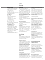
Produkt-
information
Bus-Schalt-Einheit
BSE 650-0
Bus switching unit
BSE 650-0
Unité de commutation
bus
BSE 650-0
Unità di comando bus
BSE 650-0
Bus-schakel-eenheid
BSE 650-0
Busstyreenheden
BSE 650-0
Buss-kopplings-enhet
BSE 650-0
Sběrnicová spínací
jednotka
BSE 650-0


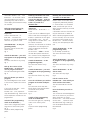
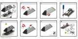
1 2
3
4
5
6
4 Sek.
ON
1 Sek.
OFF

7
8
4 Sek.
1 Sek.
10
9
4 Sek.
4 Sek.
OFF
1 Sek.
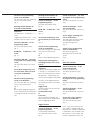
11

12
13
14
15
4 Sek.
4 Sek.
4 Sek.
1-59 Sek.
1 Min.

5
Technische Daten
• Versorgung der Busschnittstelle
erfolgt aus dem YR-System-Bus
• Kontaktbelastung
max. 250 V AC, 6 A,
Stromkreisabsicherung mit max.10 A
• Kontaktbelastung min.
5 V / 100 mA
10 V / 10 mA
24 V / 1 mA
• Zulässige Schaltleistungen:
- Motore max. 3 A
- Glühlampen max. 1300 W
- Energiesparlampen:
max. 18 x Silvania 7 W
oder 12 x Osram 11 W
- Leuchtstofflampen unkompensiert
cos ϕ 0,5 max. 800 VA
- Duo-Leuchtstofflampen
max. 1200 VA
- Parallelkompensierte
Leuchtstofflampen max. 400 VA
- Eisenkerntrafos für Niedervolt-
Halogenlampen max. 1000W
- Elektronische Trafos für Niedervolt-
Halogenlampen max.1300 W
• Schutzart IP 20
• Umgebungstemperatur 0-40° C
English
Montage
Application
Bus switching unit BSE 650-...
is designed for mounting in 55 mm
dia. switchboxes. The integrated, bi-
stable relay is equipped with a chan-
geover contact for 250 V 6A and is
used, for example, for actuating
gates, roller blinds, lighting etc. The
relay can be programmed as a timer
or as a switch.
With the switch panel mounting
accessory ZHSB 650-0, the
BSE 650-... can also be mounted on
a top-hat rail.
Operating elements
• Button for programming and func-
tion testing
• LED for status display.
Actuation
Depending on how it has been pro-
grammed, the BSE 650-... is actua-
ted by a door call, a function key in
the BTC 750-..., the touchscreen
monitor MOCT 711-... or the bus
input module BEM 650-...
Installation
Note
Electrical devices may only be instal-
led and mounted by suitably quali-
fied electrical specialists.
Conductor routing
In order to comply with the general
safety regulations for telecommuni-
cation systems according to VDE
0100 and VDE 0800, and to avoid
interference, ensure that the heavy
and light current conductors are
separately routed, observing a
distance of 10 cm. See also the rele-
vant national and local regulations.
Do not mount these devices in
boiler rooms.
Safety remark
In accordance with DIN VDE 0100
Part 410, Section 411.1.3, steps
must be taken to observe a secure
separation between bus lines and
mains voltage lines. Bus cores, mains
cores and insulating sleeves must
therefore never be allowed to come
into contact.
The bus line cable (safety extra-low
voltage) may only be stripped back
as far as necessary to allow it to be
connected. In this way, the housing
acts as a separating web for reliable
electrical isolation of SELV/PELV from
the mains voltage!
1 Terminal assignment
Remark relating to the switching
ouput:
The integrated relay is fitted with a
bi-stable switching contact. Marked
vibrations during transport can
result in this changing over to the
switch-through status. If the mains
power is connected, it is possible for
there to be live voltage at the out-
put. After switching on the
BSE 650-... (connection at the
YR bus), the relay is always set to
the „Off status“.
Commissioning
Once the device is completely instal-
led, commissioning/programming
can take place. Switch on the mains
voltage.
Functional remark
During a call, background noise cau-
sed by the data transmission may be
perceptible.
Programming/initial
commissioning
Programming for the system can
take place at any device manually or
using a PC connected to the
MOCT 711-... or to the PRI 602-...
and BIM 650-... . The PC program-
ming software BPS 650-... must be
separately ordered on CD.
Even when PC programming, all
devices must be accessible at least
once more.
Manual programming
During programming, actuation and
the ON time of the bus switching
unit BSE 650-... are defined. Only

6
the buttons BTS/BTC 750-... and
BTLM 650-... for actuation can be
manually programmed. For pro-
gramming a key and an LED as a
status display and functional testing
are available.
Defining control buttons for
actuation of the BSE 650-... .
Important!
There is no BTLM 650-... or
BTLE 050-... activated. The
BSE 650-... can only be programmed
when the YR system is active.
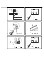
Switch BSG 650-... to the pro-
gramming mode;
The status LED at the BSG 650-...
flashes evenly.
Fig. 2
Switch the BSE 650-... you wish
to program to the programming
mode;
The status LED flashes very slowly.
Fig. 3
Pick up the receiver of the
BTS/BTC 750-... at which you
wish to program a button;
The call connected signal sounds.
Fig. 4
Press the button you wish to
program;
An acknowledgement tone sounds
in the receiver. Replace the receiver.
Fig. 5
If you wish this BSE 650-... to be
actuated from several
BTS/BTC 750-... units, repeat the
steps described for Fig. 4 and 5 until
all the telephones / BTLM units are
programmed.
Switch off the programming
mode at the BSG 650-... ;
Status LED is extinguished, opera-
ting status of the overall system.
Fig. 6
or process other programming
points.
Defining call buttons for actua-
tion of the BSE 650-... which
actuate the BSE 650-... with the
function „secondary signal con-
troller“ in parallel to a
BTS/BTC 750-... .
Important!
No BTLM 650-... or BTLE 051-... is
active.
If you wish for an additional signal
to be issued when actuating the call
button, in parallel to the call signal
at the BTS/BTC 750-..., the swit-
ching contact in the BSE 650-... can
be used for actuation.
However, the call button at the door
loudspeaker must already be pre-
viously assigned to the relevant
BTS/BTC 750-... .
At a BSE 650-... either a control
function or a parallel connected
NSC function can be programmed.
Double assignment is not possible.
Switch the BSG 650-... to the
programming mode;
The status LED flashes evenly.
Fig. 2
Switch the BSE 650-... you wish
to program to the programming
mode;
The status LED flashes very slowly.
Fig. 3
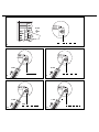
Press the call button you wish to
program at the door loudspea-
ker;
The status LED at the BSE 650-...
briefly flashes faster and the door
call sounds at the parallel
BTS/BTC 750-... .
Fig. 7
Switch off the programming
mode at the BSG 650-...
The status LED goes out, operating
status of the overall system.
Fig. 6
or process other programming
points.
Deleting the control button for
actuation of the BSE 650-... .
Buttons which act on a BSE 650-...
are generally individually deleted,
i.e. when the BSE is in the delete
mode, each button you wish to
delete must be selectively accessed
and deleted.
Call buttons with NSC function can
only be overwritten. In order to
delete a button programmed with
an NSC function, this must first be
overwritten with a button at the
BTS/BTC750-... (control function).
The key can subsequently be dele-
ted.
Switch the BSG 650-... to the
programming mode;
(if not already switched on)
The status LED flashes evenly.
Fig. 2
Switch the BSE 650-... you wish
to program to the programming
mode;
The status LED flashes very slowly.
Fig. 3
Switch the BSE 650-... to the
delete mode;
The status LED stays alight
Fig. 8
Lift the receiver at the
BTS/BTC 750-... from which you
wish to delete the button;
The call connected tone sounds.
Fig. 4
Press the button you wish to
delete;
You will hear an acknowledgement
tone in the receiver. If you wish to
delete the button in several
BTS/BTC 750-... units which actuate
this BSE 650-... , repeat the steps
described under Fig. 4 and Fig. 5
until all telephone buttons have
been deleted.
Fig. 5

7
Switch off the programming
mode at the BSG 650-...
The status LED goes out, operating
status of the overall system.
Fig. 6
Defining the bell buttons for
actuation of the BSE 650-...
Important!
The BTLM 650-... or BTLE 051-... is
active.
Programming the BSE 650-... is only
possible if the YR system is active.
Switch the BSG 650-... to the
programming mode;
The status LED flashes evenly.
Fig. 2
BTLM 650-... or BTLE 051-... acti-
vated
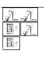
Fig. 13
Switch the BSE 650-... you wish
to program to the programming
mode;
The status LED flashes very slowly.
Fig. 14
At the door loudspeaker, press
the call button which you wish
to actuate the BSE 650-... ;
Fig. 15
Switch off the programming
mode at the BSG 650-... ;
The status LED goes out, operating
status of the overall system.
Fig. 6
or
process other programming points
such as defining the switching time /
switching function of the relay con-
tact.
Deleting the bell buttons for
actuation of the BSE 650-...
Switch the BSG 650-... to the
programming mode;
The status LED flashes evenly.
Fig. 2
BTLM 650-... or BTLE 051-... acti-
vated
Fig. 13
At the door loudspeaker, press
the call button you wish to dele-
te
Fig. 15
Switch off the programming
mode at the BSG 650-... ;
The status LED goes out, operating
status of the overall system.
Fig. 6
or
process other programming points
Defining the switching time /
switching function of the relay
contact
Important!
If you pause for periods longer than
5 seconds, i.e. if the button at the
BSE is not actuated for this period,
the BSE 650-... automatically swit-
ches out of the programming mode.
The relay can be programmed for
the switching function in two diffe-
rent ways.
Toggle mode
On/off function every time the but-
ton is actuated
(as-delivered status).
or
Time relay
When actuating the button, the
relay switches for the programmed
time (retriggering possible).
Toggle function
Switch the BSG 650-... to the
programming mode;
(if not already switched on)
The status LED flashes evenly.
Fig. 2
Switch the BSE 650-... you wish
to program to the programming
mode;
The status LED flashes very slowly.
Fig. 3
Switch the BSE 650-... to the
time setting mode;
The status LED flashes unevenly 3:1
Fig. 9
Set the toggle switching func-
tion at the BSE 650-... ,
save and at the same time switch
off the programming mode.
The status LED goes out
Fig. 10
Switch off the programming
mode at the BSG 650-...
The status LED goes out,
operating status of the overall
system.
Fig. 6
or
Time relay function
Switch the BSG 650-... to the
programming mode;
(if not yet switched on)
The status LED flashes evenly.
Fig. 2
Switch the BSE 650-.. you wish
to program to the programming
mode;
The status LED flashes very slowly.
Fig. 3
Switch the BSE 650-... to the
time setting mode;
The status LED flashes unevenly 3:1
Fig. 9
Set the time relay switching
function at the BSE 650-... ;
The status LED flashes quickly
Fig. 11
In the „time relay switching func-
tion“ mode, a programming time
limitation of 5 seconds is integrated.
If the button is not actuated at the
BSE within this time, the BSE 650-...
switches automatically out of the

8
programming mode and saves the
minimum time of 0.4 secs. If the key
at the BSE is actuated several times,
each actuation increments the time
setting up to a maximum of 19
minutes.
The time of the last actuation cor-
responds to the number of seconds
which is added to the minutes.
Example
For a time setting of 3 mins. 15
secs. , actuate the Programming
mode button at the BSE 4 times,
releasing the button on the last
actuation only after 15 secs.
Maximum time setting 19 minutes,
59 seconds.
The time of the last button actu-
ation at the BSE 650 -... determi-
nes the switching time of the relay
from 1 to 59 secs., before which
each time the button is actuated
increases the switching time by one
minute up to a maximum of 19
minutes.
Fig. 12
Wait 5 seconds until the BSE 650-...
has switched out of the programm-
ing mode. Each actuation of the
button at the BSE 650-... will other-
wise change the switching time.
Switch off the programming
mode at the BSG 650-... ;
The status LED goes out, operating
status of the overall system.
Fig. 6
Note!
To allow changes to be made to the
programming at a later time without
problems (i.e. without direct access
to each individual device) the pro-
gramming configuration must be
saved using a PC. In addition,
groups can be formed and scenarios
generated by means of PC program-
ming. The PC can be connected via
the MOCT 711-... or the PRI 602-...
and BIM 650-... . The PC program-
ming software BPS 650-... on CD
must be ordered separately.
Specifications
• The power supply to the system is
provided by the YR system bus
• Contact load max. 250 V AC,
6 A, circuit fusing with max.10 A
• Contact load min.
5 V / 100 mA
10 V / 10 mA
24 V / 1 mA
• Admissible switching outputs:
- Motors max. 3 A
- Light bulbs max. 1300 W
- Energy saving lamps
max. 18 x Silvania 7 W
or 12 x Osram 11 W
- Fluorescent lamps, uncorrected cos
ϕ 0.5 max. 800 VA
- Duo-fluorescent lamps
max. 1200 VA
- Parallel corrected fluorescent lamps
max. 400 VA
- Iron-core transformers for low-vol-
tage halogen lamps max. 1000W
- Electronic transformers for low-vol-
tage halogen lamps max.1300 W
• Protection system IP 20
• Ambient temperature 0-40° C
Français
Montage
Application
L'unité de commutation bus
BSE 650-... est conçue pour être
montée dans des prises de Ø 55
mm. Le relais bistable incorporé est
équipé d'un contact inverseur pour
250 V 6A et il sert p. ex. à comman-
der les portails, volets roulants, éclai-
rages, etc. Le relais peut être pro-
grammé en tant que minuterie ou
en tant qu'interrupteur.
L'accessoire pour montage dans le
tableau de distribution ZHSB 650-0
permet également de monter la
BSE 650-... sur barre DIN.
Eléments de commande
•Touche pour la programmation et
le contrôle fonctionnel
• DEL pour l'affichage de l'état.
Commande
La commande de la BSE 650-... s'ef-
fectue, en fonction de la programm-
ation, par l'intermédiaire de l'appel
de porte, d'une touche de fonction
du BTC 750-..., du moniteur à écran
tactile MOCT 711-..., ou par l'inter-
médiaire du module d'entrée bus
BEM 650-...
Installation
Attention
L'installation et le montage d'appar-
eils électriques ne doivent être réali-
sés que par un spécialiste en électri-
cité.
Câblage
Pour satisfaire aux dispositions de
sécurité générales relatives aux
installations de télécommunication
selon VDE 0100 et VDE 0800, et
pour éviter les influences perturba-
trices, il est nécessaire de procéder à
une pose séparée des lignes à cou-
rant fort et des lignes à courant fai-
ble. Une distance de 10 cm doit être
respectée. Se reporter également
aux dispositions nationales corre-
spondantes.
Ne pas monter les appareils dans
la chaufferie.
-
 1
1
-
 2
2
-
 3
3
-
 4
4
-
 5
5
-
 6
6
-
 7
7
-
 8
8
-
 9
9


SSS BSE 650-0 Manuel utilisateur
- Taper
- Manuel utilisateur
- Ce manuel convient également à
dans d''autres langues
- English: SSS BSE 650-0 User manual
Autres documents
-
Vivanco BTC 700 Manuel utilisateur
-
INFOSEC SMART LINE 1000 VA Manuel utilisateur
-
 bsg BioZone AC 05 Le manuel du propriétaire
-
Siemens BR15C01SA/01 Manuel utilisateur
-
-
LG GR-P62F Le manuel du propriétaire
-
Whirlpool KN6M66SA(W)/FR S Mode d'emploi
-
-
 Budda 212 COMBO Manuel utilisateur
-
CARLO GAVAZZI BSE-MAG Guide d'installation

