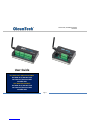
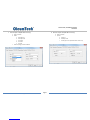
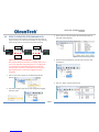
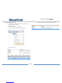
OleumTech WG-2410-DH2 Manuel utilisateur
- Taper
- Manuel utilisateur


Page 2
DH1 BASE UNIT / DH2 WIRELESS GATEWAY
USER GUIDE
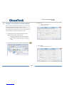
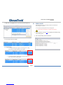
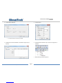
Contents (Index on Next Page)
Contents (Index on Next Page) ................................................................................... 2
PREFACE/SAFETY ......................................................................................................... 4
1. COMPLIANCES/CONFORMITÉ ........................................................................ 5
2. CERTIFICATIONS ............................................................................................. 6
3. PRODUCT & SYSTEM OVERVIEW ................................................................... 7
4. HARDWARE OVERVIEW ................................................................................. 9
5. ITEMS REQUIRED FOR SETUP ....................................................................... 10
6. CONFIGURATION/INSTALLATION SEQUENCE .............................................. 11
7. LED STATES (STATUS INDICATORS) .............................................................. 12
8. WIRING DIAGRAMS (SERIAL AND POWER) .................................................. 13
9. GROUNDING BEST PRACTICES ..................................................................... 16
10. INSTALLATION .............................................................................................. 18
11. RF SETUP ...................................................................................................... 21
12. BreeZ® PROJECT FILE CREATION .................................................................. 23
13. BreeZ® MAIN SCREEN VIEW ......................................................................... 29
14. MODBUS MAPPING TABLE MANAGEMENT ................................................. 30
15. ADDING IMPORT POINTS TO MODBUS TABLE ............................................. 33
16. EDITING GATEWAY PROPERTIES .................................................................. 35
17. COM PORT SETUP ON PC AND BreeZ® ......................................................... 38
18. GATEWAY UPDATE (FIRMWARE UPGRADE) ................................................ 40
19. CONNECT TO GATEWAY FUNCTION IN BreeZ® ............................................ 41
20. TRANSMITTER UPDATE – CABLE METHOD (PROGRAM / CONFIGURE) ....... 43
21. POLLING MODBUS REGISTERS USING BreeZ® ............................................. 44
22. DEBUG MODE .............................................................................................. 45
23. RF REFRESH TIME TAG(S) ............................................................................. 46
24. MODBUS WRITE FUNCTION AND WRITING TO GATEWAY .......................... 47
25. PEER-TO-PEER/REPEATER/SHARING DATA .................................................. 49
26. MAPPING AN IMPORT TO AN OUTPUT ON DH1 BASE UNIT ........................ 51
27. MAPPING AN IMPORT TO AN OUTPUT ON WIRELESS MULTI-I/O MODULE 52
28. RS485 I/O EXPANSION SYSTEM WITH GATEWAY ........................................ 54
29. MODBUS MASTER FUNCTION ...................................................................... 58
30. ROC LINK MASTER ........................................................................................ 62
31. SAVING PROJECT FILE TO GATEWAY ............................................................ 64
32. RETRIEVING PROJECT FILE FROM GATEWAY ............................................... 65
33. WIRELESS SITE SECURITY KEY....................................................................... 66
34. TROUBLESHOOTING – GATEWAY ................................................................ 68
35. TROUBLESHOOTING – TRANSMITTER .......................................................... 69
36. GENERAL MAINTENANCE ............................................................................. 72
37. GLOSSARY .................................................................................................... 72
38. WARRANTY (LIMITED) .................................................................................. 75
39. REVISION HISTORY ....................................................................................... 76
Controlled Copy

Page 3
DH1 BASE UNIT / DH2 WIRELESS GATEWAY
USER GUIDE
Index
ADDING IMPORT POINTS TO MODBUS TABLE .......................................................... 33
BreeZ® MAIN SCREEN VIEW ...................................................................................... 29
BreeZ® PROJECT FILE CREATION ............................................................................... 23
CERTIFICATIONS .......................................................................................................... 6
COM PORT SETUP ON PC AND BreeZ® ...................................................................... 38
COMPLIANCES/CONFORMITÉ ..................................................................................... 5
CONFIGURATION/INSTALLATION SEQUENCE ........................................................... 11
CONNECT TO GATEWAY FUNCTION IN BreeZ® ......................................................... 41
DEBUG MODE ........................................................................................................... 45
EDITING GATEWAY PROPERTIES ............................................................................... 35
GATEWAY UPDATE (FIRMWARE UPGRADE) ............................................................. 40
GENERAL MAINTENANCE .......................................................................................... 72
GLOSSARY ................................................................................................................. 72
GROUNDING BEST PRACTICES .................................................................................. 16
HARDWARE OVERVIEW .............................................................................................. 9
INSTALLATION ........................................................................................................... 18
ITEMS REQUIRED FOR SETUP .................................................................................... 10
LED STATES (STATUS INDICATORS) ........................................................................... 12
MAPPING AN IMPORT TO AN OUTPUT ON DH1 BASE UNIT ..................................... 51
MAPPING AN IMPORT TO AN OUTPUT ON WIRELESS MULTI-I/O MODULE ............. 52
MODBUS MAPPING TABLE MANAGEMENT .............................................................. 30
MODBUS MASTER FUNCTION ................................................................................... 58
MODBUS WRITE FUNCTION AND WRITING TO GATEWAY ....................................... 47
PEER-TO-PEER/REPEATER/SHARING DATA ............................................................... 49
POLLING MODBUS REGISTERS USING BreeZ®........................................................... 44
PRODUCT & SYSTEM OVERVIEW ................................................................................ 7
RETRIEVING PROJECT FILE FROM GATEWAY ............................................................ 65
REVISION HISTORY .................................................................................................... 76
RF REFRESH TIME TAG(S) .......................................................................................... 46
RF SETUP ................................................................................................................... 21
ROC LINK MASTER ..................................................................................................... 62
RS485 I/O EXPANSION SYSTEM WITH GATEWAY ..................................................... 54
SAVING PROJECT FILE TO GATEWAY ......................................................................... 64
TRANSMITTER UPDATE – CABLE METHOD (PROGRAM / CONFIGURE) .................... 43
TROUBLESHOOTING – GATEWAY ............................................................................. 68
TROUBLESHOOTING – TRANSMITTER ....................................................................... 69
WARRANTY (LIMITED) ............................................................................................... 75
WIRELESS SITE SECURITY KEY .................................................................................... 66
WIRING DIAGRAMS (SERIAL AND POWER) ............................................................... 13
Controlled Copy

Page 4
DH1 BASE UNIT / DH2 WIRELESS GATEWAY
USER GUIDE
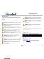
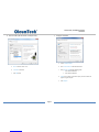
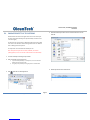
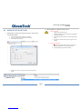
PREFACE/SAFETY
Thank you for choosing the DH1 Base Unit/DH2 Wireless Gateway by OleumTech™.
This document describes the hardware components and how to install and operate
the Gateway.
This document also describes how to maintain and troubleshoot the device.
CAUTION: Field wiring connections shall be made in accordance with Article 504 of
the National Electrical Code, ANSI/NFPA70.
CAUTION: The Gateway must be installed within an enclosure that requires a tool to
access. This is to prevent inadvertent disconnection of any of the power wiring,
signal wiring or communication cables.
ATTENTION: Le Gateway doit être installé dans une enceinte qui nécessite un outil
d'accès. Ce est pour éviter toute déconnexion accidentelle de l'un des câbles câblage
de puissance, câblage ou de communication signaux.
WARNING: Ensure installation of the Gateway meets applicable state and national
electrical code requirements. The installation of the Gateway should only be
performed by a qualified installer or a factory representative.
AVERTISSEMENT: Veiller à l'installation de la passerelle répond Etat et des exigences
nationales de code de l'électricité. L'installation de la Gateway ne doit être effectuée
par un installateur qualifié ou un représentant de l'usine.
WARNING: To prevent ignition of flammable or combustible atmospheres,
disconnect power before servicing.
AVERTISSEMENT: Pour éviter l'inflammation d'atmosphères inflammables ou
combustibles, débrancher l'alimentation avant l'entretien.
WARNING: EXPLOSION HAZARD – Substitution of components impair suitability for
Zone 2.
AVERTISSEMENT: RISQUE D'EXPLOSION - Le remplacement de composants nuire à la
conformité pour la Zone 2.
WARNING: EXPLOSION HAZARD – Do not separate/disconnect connectors when
energized.
AVERTISSEMENT: RISQUE D'EXPLOSION - Ne pas séparer / débrancher les
connecteurs lorsque excité.
WARNING: EXPLOSION HAZARD – Do not use USB connectors in hazardous area.
AVERTISSEMENT: RISQUE D'EXPLOSION - Ne pas utiliser les connecteurs USB en
zone dangereuse.
WARNING: EXPLOSION HAZARD – Do not service when an explosive atmosphere is
present.
AVERTISSEMENT: RISQUE D'EXPLOSION - Ne pas service lorsque une atmosphère
explosive est présente.
WARNING: EXPLOSION HAZARD – Do not use reset switch in hazardous area.
AVERTISSEMENT: RISQUE D'EXPLOSION - Ne pas utiliser le commutateur de
réinitialisation en zone dangereuse.
Note: This equipment is suitable for use in Class I, Division 2 Groups A, B, C, and D
or non-hazardous locations only.
Document Revision Level
This section provides a history of the revision changes to this document.
Revision
ECO Number
Date
Description
P
002968
10/12/2015
Revised best grounding practices section 9
Revision History
Click Here for Details
Must check Software & RF compatibility before deployment!
Controlled Copy

Page 5
DH1 BASE UNIT / DH2 WIRELESS GATEWAY
USER GUIDE
1. COMPLIANCES/CONFORMITÉ
English
Important Information to the User
This device MUST be professionally installed only by a factory representative or a trained
authorized technician.
Changes or modifications not expressly approved by the manufacturer may void the user’s
authority to operate the equipment.
This device complies with Part 15 of the FCC Rules. Operation is subject to the following
two conditions: 1) this device may not cause harmful interference, and 2) this device must
accept any interference received, including interference that may cause undesired
operation.
This product contains a FHSS (Frequency Hopping Spread Spectrum) and FSK (Frequency
Shifting Key) modulation RF transceiver for the 902-928 MHz ISM band, designed to meet
FCC 15.247, and is used in industrial control and monitoring applications.
To reduce potential radio interference to other users, install and use only the antenna
supplied by the manufacturer to ensure successful communications.
The antenna is factory sealed and MUST NOT be modified by the user.
FCC RF Exposure
To comply with FCC RF exposure compliance requirements, a separation distance of at least
20 cm must be maintained between the antenna of this device and all persons.
FCC Compliance Statement
This equipment has been tested and found to comply with the limits for a class B digital
device, pursuant to Part 15 of the FCC Rules. These limits are designed to provide reasonable
protection against harmful interference in a residential installation. This equipment
generates, uses and can radiate radio frequency energy and if not installed and used in
accordance with the instructions, may cause harmful communications to radio
communications. However, there is no guarantee that interference will not occur in a
particular installation. If this equipment does cause harmful interference to radio or
television reception, which can be determined by turning the equipment off and on, the user
is encouraged to try to correct the interference by one of the following measures:
Reorient or relocate the antenna.
Increase the separation between the equipment and receiver.
Consult the manufacturer for technical help.
This equipment has been certified to comply with the limits for a class B computing device,
pursuant to FCC Rules. In order to maintain compliance with FCC regulations, shielded cables
must be used with this equipment. Operation with non-approved equipment or use of
unshielded cables is likely to result in interference to radio and television reception. The user
is cautioned that changes or modifications made to the equipment without the approval of
the manufacturer could void the user’s authority to operate this equipment.
Controlled Copy

Page 6
DH1 BASE UNIT / DH2 WIRELESS GATEWAY
USER GUIDE
CONFORMITÉ
Françias
Informations importantes à l'utilisateur
Ce dispositif doit être installé par un professionnel que par un représentant de l'usine
ou par un technicien formé et autorisé.
Les changements ou modifications non expressément approuvés par le fabricant
peuvent annuler l'autorité de l'utilisateur à utiliser l'équipement.
Cet appareil est conforme à la partie 15 des règles de la FCC. Son fonctionnement est
soumis aux deux conditions suivantes: 1) ce dispositif ne doit pas causer
d'interférences nuisibles et 2) cet appareil doit accepter toute interférence reçue, y
compris les interférences qui peuvent causer un mauvais fonctionnement.
Ce produit contient un FHSS (Frequency Hopping Spread Spectrum) émetteur-
récepteur RF pour la bande ISM 902-928 MHz en utilisant FSK (Frequency Shifting
Key) modulation, conçu pour répondre FCC 15.247, et est utilisé dans le contrôle
industriel et les applications de surveillance.
Pour réduire les interférences radio potentielles aux autres utilisateurs, installer et
utiliser uniquement l'antenne fournie par le fabricant pour assurer une
communication réussie.
L'antenne est scellé en usine et ne doit être modifié par l'utilisateur.
FCC RF Exposure
Pour se conformer à la FCC exigences de conformité de l'exposition, une distance de
séparation d'au moins 20 cm doit être maintenue entre l'antenne de cet appareil et toutes
les personnes.
Déclaration de conformité FCC
Cet équipement a été testé et déclaré conforme aux limites d'un appareil numérique de
classe B, conformément à la partie 15 des règles de la FCC. Ces limites sont conçues pour
fournir une protection raisonnable contre les interférences nuisibles dans une installation
résidentielle. Cet équipement génère, utilise et peut émettre de l'énergie radiofréquence et,
si non installé et utilisé conformément aux instructions, peut provoquer des communications
nuisibles aux communications radio. Cependant, il ne est pas garanti que des interférences
ne se produiront pas dans une installation particulière. Si cet équipement provoque des
interférences nuisibles à la réception radio ou de télévision, ce qui peut être déterminé en
mettant l'équipement hors et sous tension, l'utilisateur est encouragé à essayer de corriger
l'interférence par une des mesures suivantes:
Réorienter ou déplacer l'antenne.
Augmenter la distance entre l'équipement et le récepteur.
Consultez le fabricant de l'aide technique.
Cet équipement a été certifié conforme aux limites d'un dispositif informatique de classe B,
conformément aux règles de la FCC. Afin de maintenir la conformité aux règlements de la
FCC, des câbles blindés doivent être utilisés avec cet équipement. L'utilisation d'équipement
ou l'utilisation de câbles non blindés non approuvé est susceptible d'entraîner des
interférences dans la réception radio et télévision. L'utilisateur est averti que les
changements ou modifications apportées à l'équipement sans l'approbation du fabricant
pourraient annuler l'autorité de l'utilisateur à utiliser cet équipement.
2. CERTIFICATIONS
Class I Division 2, Groups A, B, C, D T4 Ex nA nC IIC T4
Class I, Zone 2, AEx nA nC IIC, T4 Gc
Tamb: -40 oC to +80 oC; w/optional LCD -20 oC to +70 oC
Power Supply: 9-30 Vdc Powered by Class 2 Circuit
II 3 G
ATEX 15ATEX#TBDX, Ex nA nC IIC T4 Gc
Tamb: -40 oC to +80 oC; w/ optional LCD -20 oC to +70 oC
Power Supply: 9-30 VDC (24V Typical) 0.25A Peak, 0.20
Continuous
IECEx TBD, Ex nA nC IIC, T4 Gc
Tamb: -40 oC to +80 oC; w/ optional LCD -20 oC to +70 oC
Power Supply: 9-30 VDC (24V Typical) 0.25A Peak, 0.20
Continuous
Controlled Copy

Page 7
DH1 BASE UNIT / DH2 WIRELESS GATEWAY
USER GUIDE
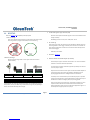
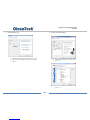
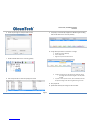
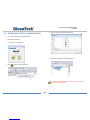
3. PRODUCT & SYSTEM OVERVIEW
SHARED PRODUCT HIGHLIGHTS
- Serves as a Primary Data Collection Point in OleumTech™ Wireless Sensor
and I/O Network
- Advanced Networking Architecture:
Point-to-Multipoint/Star (Gateway-to-End Nodes) & Peer-to-Peer/Repeater
(Gateway-to- Gateway)
- Works with Gateways / Transmitters / Wireless I/O Modules /
RS485 I/O Expansion System
1x RTU Ports (Serial) - RS232 or RS485 (Software/Jumper Configurable)
- Modbus Master or Slave
- LevelMaster ASCII Slave
- ROC-Link Master (Opcode 10 and 17)
DH1 BASE UNIT ADDITIONAL PRODUCT HIGHLIGHTS
Onboard I/O
- 4x 0-5 V Inputs
- 2x Digital/Discrete Inputs
- 2x Digital/Discrete Outputs
RS48S Port
- Modbus Master or Slave
- LevelMaster ASCII Slave
Controlled Copy

Page 8
DH1 BASE UNIT / DH2 WIRELESS GATEWAY
USER GUIDE
ADVANCED NETWORKING ARCHITECTURE
The DH1 Base Unit or DH2 Wireless Gateway plays a vital role in the OleumTech Wireless
Sensor Network. When used as a primary Gateway, it serves as the central collection point of
data, which then can be served to any Modbus Master device. A Wireless Gateway can
collect data from OleumTech wireless end nodes such as Wireless Transmitters and Wireless
I/O Modules in a “star network” or point-to-multipoint structure. What sets the OleumTech
Gateway apart from rest the competition is its ability to wirelessly share data and control
outputs amongst multiple Gateways in a same network known as “peer-to-peer”
architecture. Thus, OleumTech Wireless System is highly scalable, allowing the creation of a
basic network containing a handful of end nodes to a much more robust network containing
hundreds of wireless nodes and Gateways stretched by many miles.
FLEXIBLE COMMUNICATION
The Serial/RTU Port can be independently configured using BreeZ® software as a Modbus
Master, Modbus Slave, LevelMaster Slave, or ROC-Link Master. In a typical deployment, DH1
Base Unit/DH2 acts as a Modbus Slave device that is connected to a Modbus Master device
such as a RTU, PLC, HMI, DCS, or long-haul radio system over Modbus Serial RS232/485.
When used as a secondary Gateway, DH1 Base Unit/DH2 can also function as a Modbus
Master device to collect critical process values from a Modbus Slave device. The polled data
can be served to a Modbus Master device or can be shared across over the air to another
Gateway in a network.
OLEUMTECH WIRELESS SENSOR NETWORK
Reliable, Robust Wireless Performance
Eliminates Costly Conduits and Wiring
Monitor/Control Process Conditions 24/7
Reduces Labor, Installation and Maintenance Costs
Helps Meet Regulatory Requirements
Industrial Strength Performance and Durability
BreeZ® SOFTWARE
Microsoft Windows®-based software tool for configuring Wireless Devices such as
Wireless Transmitters, Gateways, and I/O Expansion Modules
Features Quick and Easy Project Creation Wizard
Modbus Master Read/Write Function for Test Verification
Allows Project Files to be Saved to and Retrieved from Gateway
Easily Create Flexible/Sophisticated Network Architecture
And Much More
Controlled Copy


Page 10
DH1 BASE UNIT / DH2 WIRELESS GATEWAY
USER GUIDE
5. ITEMS REQUIRED FOR SETUP
Gateway Setup
DH1 Base Unit / DH2 Wireless Gateway
External Power Source for Gateway (9-30 VDC)
*(DH2: 9-24 VDC Prior to SN: SM11266715)
Antenna for Gateway (Bulkhead, Omni, or Yagi)
Antenna Cable (N to MMCX Connector)
N to N Antenna Cable and Lighting Arrestor (Optional)
External Enclosure for Gateway (NEMA)
DIN Rail (35mm)
Other Device Setup
OleumTech Wireless Transmitter(s)
OleumTech Wireless Gateway(s) (DH1 Base Unit or DH2)
OleumTech Wireless I/O Modules
OleumTech RS485 I/O Expansion System
Configuration Cables
USB to Serial Adapter (SX1000-CC9)
Gateway Configuration Cable (SX1000-CC1)
Software and PC
BreeZ® Software v5.0 or Higher Recommended
(Available on OleumTech Download Center)
PC with:
o Microsoft Windows® Vista or Later
o 1 GHz or Faster Processor
o 256 MB or More RAM
o 10 MB Hard Disk Space or More
o USB and/or Serial Port
Modbus Master
Modbus Master Device (RS232 or RS485), RTU, PLC, HMI, etc...
LevelMaster Device
Modbus Slave
Modbus Slave Device (RS232 or RS485), RTU, PLC, HMI, etc...
ROC-Link Device
Tools
Screwdriver Set including Technician’s Screwdriver, Adjustable Wrench
Any Other Tools Depending on Site and Equipment
Internet Access
Internet access required for downloading Software, Firmware, or Documents
Controlled Copy

Page 11
DH1 BASE UNIT / DH2 WIRELESS GATEWAY
USER GUIDE
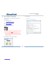
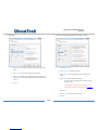
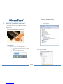
6. CONFIGURATION/INSTALLATION SEQUENCE
Configuration
1. Download and install latest BreeZ® Software v5.0 or higher to a PC
Download Center: http://support.oleumtech.com
(requires login credentials)
2. Check for latest Wireless Gateway Firmware on Download Center
3. Create a BreeZ® Project File (see sec. 12)
4. If upgrading Firmware, follow these instructions:
a. Physically Connect Gateway to PC and supply power
b. Open Connect screen and click “Flash”
c. Locate new Firmware file and click “Open”
d. DO NOT DISCONNECT OR TURN POWER OFF while upgrading
Firmware (It may take a few minutes for upgrading process to
finish)
e. Wait until LED turns off
5. Power up Gateway (9-30Vdc) and wait until boot-up sequence is complete
*(DH2: 9-24 VDC Prior to SN: SM11266715)
(LED will turn off once boot-up is complete)
6. Connect PC to Gateway (see sec. 17)
a. USB to Serial Adapter (SX1000-CC9)
b. Gateway Configuration Cable (SX1000-CC1)
7. Identify COM Port for use in BreeZ® (Device Manager)
8. Select a Gateway in BreeZ® Project Tree (see sec. 17)
9. Update Gateway with BreeZ® Project File (see sec. 18)
10. Confirm Gateway “Configuration Download OK” in Build Tab Window in
BreeZ® (see sec. 18)
Installation (see sec. 8-11)
1. Install Gateway inside a NEMA enclosure
2. Follow best grounding practices
3. Setup and connect an Antenna with Lightening Arrestor to Gateway
4. Connect Gateway to third-party Serial device(s)
5. Power up Gateway
6. Power up/reboot any impacted sensors/devices if necessary
7. Verify RF and data communications
a. Use Modbus Register Polling and Write features in BreeZ®
b. Verify communication from third-party device(s) or SCADA system
Controlled Copy

Page 12
DH1 BASE UNIT / DH2 WIRELESS GATEWAY
USER GUIDE
7. LED STATES (STATUS INDICATORS)
When device failure has occurred try following actions:
Check power source
Replace radio module
Call Tech Support
#
State
Green LED
1
Booting up
Long blink + 5 short blinks
2
Device On or Off
Off
3
Connected to PC / Updating in Progress /
Firmware Upgrade
Solid green
4
Device updated/programmed
Long blink + 5 short blinks
5
Device Failure
Continuous short blinks
Controlled Copy

Page 13
DH1 BASE UNIT / DH2 WIRELESS GATEWAY
USER GUIDE
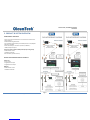
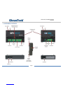
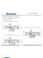
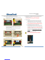
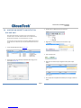
8. WIRING DIAGRAMS (SERIAL AND POWER)
Please use the following wiring diagrams and jumper settings to connect
a third-party device to the Wireless Gateway.
1. SERIAL/RTU Port (DH1 Base Unit)
a. DH1 Base Unit – RS232 Field Wiring and Jumper Settings
b. DH1 Base Unit – RS485 Half Duplex Wiring and Jumper Settings
c. DH1 Base Unit – RS485 Full Duplex Wiring and Jumper Settings
Controlled Copy


Page 15
DH1 BASE UNIT / DH2 WIRELESS GATEWAY
USER GUIDE
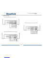
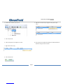
3. DH1 Base Unit RS485 Port
4. Config Port
Pin
Pin Name
Generic Modbus Device
1
GND
GND
2
Reserved
3
RX+
TX+
4
RX−
TX−
5
TX−
RX−
6
TX+
RX+
7
Reserved
8
Reserved
Pin
Pin Name
PC Configuration Cable DB9 (Pin Number)
1
Reserved
2
DEBUG
Ground (5)
3
TXD
RXD (2)
4
RXD
TXD (3)
5
CTS
RTS (7)
6
GND
GND (5)
7
RTS
CTS (6)
8
Reserved
Pin 1
Pin 1
Pin 1
Controlled Copy

Page 16
DH1 BASE UNIT / DH2 WIRELESS GATEWAY
USER GUIDE
9. GROUNDING BEST PRACTICES
1. DO NOT tie earth ground the digital and power ground terminals Wireless
Gateways.
2. The panel enclosure must be grounded to earth.
3. It is safe to mount OleumTech Wireless Gateways to panel enclosure since
the chassis and digital/power ground terminals are isolated.
4. Where bulkhead (black phantom) antennas are used, the inner surface,
outer surface, and inner wall of the hole drilled, should be isolated from
the antenna. Use the rubber washers supplied by manufacturer to isolate
the antennas from the enclosures (use thickest washer supplied by
manufacturer to isolate the antennas from the enclosures (use thickest
washer on exterior side of enclosure).
TERRE DES MEILLEURES PRATIQUES (Françias)
1. Ne pas attacher TERRE les bornes de masse et de puissance numériques
sans fil Passerelles .
2. Le boîtier du panneau doit être mis à la terre .
3. Il est sûr de monter OleumTech Wireless Gateways au boîtier du panneau
depuis le châssis et les terminaux / sol de puissance numériques sont
isolées.
4. Où cloison ( Phantom Black ) antennes sont utilisées , la surface intérieure ,
la surface extérieure , et la paroi intérieure du trou foré , doit être isolé de
l'antenne . Utilisez les rondelles en caoutchouc fournies par le fabricant
pour isoler les antennes des enceintes (utilisez la plus épaisse rondelle
fournie par le fabricant pour isoler les antennes des enceintes (utilisez la
plus épaisse rondelle sur côté extérieur de l'enceinte ) .
Controlled Copy

Page 17
DH1 BASE UNIT / DH2 WIRELESS GATEWAY
USER GUIDE
Grounding Gateways & I/O Modules:
Battery negative should never be common with earth ground.
For fiberglass enclosures, the backplane inside may be connected
to earth ground. Typically, there is a lug specifically for this
connection. The equipment inside the enclosure however, should
not be common with the backplane in this case.
For steel enclosures, battery negative should not be common with
the enclosure as the enclosure will usually be common with the
pole supporting it (basically earth ground).
A. Where bulkhead (black phantom) antennas are used, the inner surface,
outer surface, and inner wall of the hole drilled, should be isolated from
the antenna. Use the rubber washers supplied by the manufacturer to
isolate the antennas from the enclosures (use thickest washer on exterior
side of enclosure).
B. Where external antennas, such as omni-directional and yagi, are utilized, a
polyphaser is typically used. The actual connection between lightening
arrestor and antenna cable should be isolated. The lightening arrestor
itself has its own lug designed to be connected to earth ground.
Once all wiring and grounding recommendations have been
followed it is important to test the ground resistance at the
grounding rod to assure a good ground. The most effective
grounding method is direct connection to earth ground with
minimal impedance. An impedance of less than 5 Ohms is
recommended.
For more details on proper grounding electrodes and grounding
electrode conductors, consult the National Electrical Code.
CAUTION: Ensure field wiring connections are in accordance with Article
504 of the National Electrical Code, ANSI/NFPA70. For more details on
proper grounding electrodes and grounding electrode conductors, consult
the National Electrical Code.
Terre passerelles et modules E / S: (Français)
Négative batterie ne doit jamais être commun avec la terre.
Pour les enveloppes en fibre de verre, le fond de panier à l'intérieur peut
être relié à la terre. Typiquement, il se agit d'un ergot spécifiquement
pour cette connexion. L'équipement intérieur de l'enceinte ne devrait
toutefois pas être commun avec le fond de panier dans ce cas.
A. Pour les enveloppes d'acier, négatif de la batterie ne doit pas être commun
avec l'enceinte, l'enceinte sera généralement commun avec le pôle le
soutenir (essentiellement de la terre).
A. Où cloison (Phantom Black) antennes sont utilisées, la surface intérieure,
la surface extérieure, et la paroi intérieure du trou foré, doit être isolé de
l'antenne. Utilisez les rondelles en caoutchouc fournies par le fabricant pour
isoler les antennes des enceintes (utiliser la plus épaisse rondelle sur le côté
extérieur de l'enceinte).
B. Lorsque les antennes externes, tels que omnidirectionnelle et Yagi, sont
utilisés, un Polyphaser est généralement utilisé. La connexion réelle entre
Polyphaser et le câble d'antenne doit être isolé. Le Polyphaser lui-même a sa
propre patte destinée à être reliée à la terre.
Une fois que toutes les recommandations de câblage et de mise à la
terre ont été suivies, il est important de tester la résistance du sol à la
tige de mise à la terre pour assurer un bon sol. La méthode de mise à la
terre la plus efficace est la connexion directe à la terre avec une
impédance minimale. Une impédance inférieure à 5 Ohms
recommandée.
Controlled Copy

Page 18
DH1 BASE UNIT / DH2 WIRELESS GATEWAY
USER GUIDE
10. INSTALLATION
The following procedure describes how to install a Gateway inside a NEMA 4X-
type enclosure (or an enclosure with a minimum IP 54 rating and that complies
with IEC 60079-0 and IEC60079-15). Before you perform this procedure, be
sure the Gateway meets applicable grounding requirements in the enclosure –
see previous section).
Special Conditions for Use
I. Install the Gateway inside a NEMA 4X-type enclosure (or an enclosure with
a minimum IP 54 rating that complies with IEC 60079-0 and IEC60079-15).
Mounting of the Gateway within a suitable enclosure will cause the internal
ambient enclosure temperature to be higher than the maximum external
enclosure ambient temperature. The Gateway shall not form part of the
external enclosure (panel mounted, for example). All cable entries into the
enclosure shall be fitted with IECEx certified cable glands that have a
minimum ingress protection of IP54. The cable glands shall have an
operating temperature range equal to or greater than the ambient
operating temperature.
II. USB connectors are not for use in hazardous areas and will be internal to
installation in an IECEx certified IP54 enclosure.
III. Any Ethernet connectors used shall be checked to ensure that the
mechanical retaining clip is undamaged and provides a mechanically
secured and retained connection.
IV. Transient protection shall be provided on the supply to limit transients to a
maximum of 42 Vpk.
INSTALLATION (FRANÇAIS)
La procédure suivante décrit l'installation correcte d'un Gateway.
Avant d'effectuer cette procédure, se assurer que le Gateway répond aux
exigences de mise à la terre en vigueur dans l'enceinte - voir la section
précédente).
Conditions spéciales pour une utilisation
I. Installez le Gateway l'intérieur d'un boîtier NEMA 4X-type (ou une enceinte
avec un minimum IP 54 notation compatible avec la CEI 60079-0 et
IEC60079-15). Le montage de l' Gateway dans un boîtier approprié
provoquera la température interne de l'enceinte ambiante soit supérieure à
la température ambiante enceinte externe maximale. Le Gateway ne fait
pas partie de l'enceinte externe (monté sur panneau, par exemple). Toutes
les entrées de câble dans l'enceinte doivent être munis d'IECEx presse-
étoupes conformes qui ont un minimum de protection d'entrée IP54. Les
presse-étoupe ont une plage de température de fonctionnement égale ou
supérieure à la température ambiante de fonctionnement.
II. Connecteurs USB ne sont pas pour une utilisation en zone dangereuse et
seront internes à l'installation dans un certifié IP54 IECEx.
III. Les connecteurs Ethernet utilisés doit être vérifiée pour se assurer que le
clip de fixation mécanique est en bon état et offre une connexion sécurisée
et mécaniquement retenu.
IV. Protection contre les transitoires doivent être fournis sur la fourniture de
limiter les transitoires à un maximum de 42 Vpk.
Controlled Copy

Page 19
DH1 BASE UNIT / DH2 WIRELESS GATEWAY
USER GUIDE
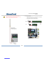
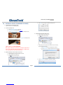
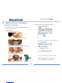
1. Mount Gateway onto DIN Rail Inside of an Enclosure
a. Remove top cover on Gateway held by 2 screws, then loosen the
2 DIN Rail Clamp screws
b. Loop the connector ends through the opening in the bottom of
the enclosure, including compression fitting, before mounting
devices in the enclosure
c. Mount Gateway onto DIN Rail (DIN1: 32 mm/1.3” or DIN3: 35
mm/1.4” DIN) and Adjust DIN Rail Clamp
d. Tighten DIN Rail Clamp Screw and Reattach Cover
2. Drilling a Hole on the Bottom of Enclosure for Routing Antenna
Cable May Be Required (5/16” or larger diameter hole
recommended, user must supply own O-ring/sealing)
3. Connect Antenna
a. Firmly hold and connect MMCX end of the antenna cable to
Gateway Radio (listen for a “click” sound for confirmation)
b. Connect Lightning Arrestor (optional – highly recommended)
c. Drilling a hole may be required for routing antenna cable – use
5/16” or larger diameter, user must supply own O-ring/sealing
d. Use proper fittings to seal hole for antenna cable
e. Where bulkhead (black phantom) antennas are used, the inner
surface, outer surface, and inner wall of the hole drilled, should
be isolated from the antenna. Use the rubber washers supplied by
manufacturer to isolate the antennas from the enclosures (use
thickest washer supplied by manufacturer to isolate the antennas
from the enclosures (use thickest washer on exterior side of
enclosure).
f. Install antenna and connect all cables
g. Must install omni or bulkhead antenna in upright position
Do not mount sideways! (Ne pas monter sur le côté !)
Controlled Copy

Page 20
DH1 BASE UNIT / DH2 WIRELESS GATEWAY
USER GUIDE
h. Do not install other antenna on the same vertical plane – provide
sufficient vertical separation (Ne installez pas autre antenne sur le même
plan vertical - assurer la séparation verticale suffisante.)
4. Connect External Power
a. Gateway accepts 9-30 VDC, 12 V recommended (Use 18-24 gauge
wires) *(DH2: 9-24 VDC Prior to SN: SM11266715)
b. LED will flash 5 times when the device powers up
DH2
Base Unit
Controlled Copy
La page est en cours de chargement...
La page est en cours de chargement...
La page est en cours de chargement...
La page est en cours de chargement...
La page est en cours de chargement...
La page est en cours de chargement...
La page est en cours de chargement...
La page est en cours de chargement...
La page est en cours de chargement...
La page est en cours de chargement...
La page est en cours de chargement...
La page est en cours de chargement...
La page est en cours de chargement...
La page est en cours de chargement...
La page est en cours de chargement...
La page est en cours de chargement...
La page est en cours de chargement...
La page est en cours de chargement...
La page est en cours de chargement...
La page est en cours de chargement...
La page est en cours de chargement...
La page est en cours de chargement...
La page est en cours de chargement...
La page est en cours de chargement...
La page est en cours de chargement...
La page est en cours de chargement...
La page est en cours de chargement...
La page est en cours de chargement...
La page est en cours de chargement...
La page est en cours de chargement...
La page est en cours de chargement...
La page est en cours de chargement...
La page est en cours de chargement...
La page est en cours de chargement...
La page est en cours de chargement...
La page est en cours de chargement...
La page est en cours de chargement...
La page est en cours de chargement...
La page est en cours de chargement...
La page est en cours de chargement...
La page est en cours de chargement...
La page est en cours de chargement...
La page est en cours de chargement...
La page est en cours de chargement...
La page est en cours de chargement...
La page est en cours de chargement...
La page est en cours de chargement...
La page est en cours de chargement...
La page est en cours de chargement...
La page est en cours de chargement...
La page est en cours de chargement...
La page est en cours de chargement...
La page est en cours de chargement...
La page est en cours de chargement...
La page est en cours de chargement...
La page est en cours de chargement...
-
 1
1
-
 2
2
-
 3
3
-
 4
4
-
 5
5
-
 6
6
-
 7
7
-
 8
8
-
 9
9
-
 10
10
-
 11
11
-
 12
12
-
 13
13
-
 14
14
-
 15
15
-
 16
16
-
 17
17
-
 18
18
-
 19
19
-
 20
20
-
 21
21
-
 22
22
-
 23
23
-
 24
24
-
 25
25
-
 26
26
-
 27
27
-
 28
28
-
 29
29
-
 30
30
-
 31
31
-
 32
32
-
 33
33
-
 34
34
-
 35
35
-
 36
36
-
 37
37
-
 38
38
-
 39
39
-
 40
40
-
 41
41
-
 42
42
-
 43
43
-
 44
44
-
 45
45
-
 46
46
-
 47
47
-
 48
48
-
 49
49
-
 50
50
-
 51
51
-
 52
52
-
 53
53
-
 54
54
-
 55
55
-
 56
56
-
 57
57
-
 58
58
-
 59
59
-
 60
60
-
 61
61
-
 62
62
-
 63
63
-
 64
64
-
 65
65
-
 66
66
-
 67
67
-
 68
68
-
 69
69
-
 70
70
-
 71
71
-
 72
72
-
 73
73
-
 74
74
-
 75
75
-
 76
76


OleumTech WG-2410-DH2 Manuel utilisateur
- Taper
- Manuel utilisateur
dans d''autres langues
- English: OleumTech WG-2410-DH2 User manual
Documents connexes

Autres documents
-
 Packet Power Ethernet Gateway Version 3 Manuel utilisateur
-
Weidmuller IE-UGW-2TX-2RS232-485 Mode d'emploi
-
Spectrum Controls WP-G-242-P1 Guide de démarrage rapide
-
 ZyXEL Communications Network Card 70 Manuel utilisateur
-
 ZyXEL Communications ZyXEL ZyWALL 5 Le manuel du propriétaire
-
 ZyXEL Communications Network Card 5 Manuel utilisateur
-
 ZyXEL Communications ZYWALL 2 PLUS START V4.03 Guide de démarrage rapide
-
 ZyXEL Communications 70 Manuel utilisateur
-
Anybus AB7316 Guide d'installation
-
 Sollae Systems SMG-5620 Manuel utilisateur


