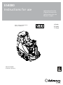
Nilfisk ES4000 Le manuel du propriétaire
- Catégorie
- Machine à plancher
- Taper
- Le manuel du propriétaire

Advance Models:
56344200, 56344210
ES4000
Instructions for use Instructions for Use
Original Instructions
Instrucciones de uso
Mode d’ emploi
2/2011 revised 1/2018 REV B
Form no. 56091013
A-English
B-Español
C-Français

A-2 / ENGLISH
A-2 - FORM NO. 56091013 - ES4000
TABLE OF CONTENTS
page
Introduction .......................................................................................................... A-2
Cautions and Warnings .......................................................................................A-3
Know Your Machine ....................................................................................A-4 - A-5
Control Panel .......................................................................................................A-6
Prepare the Machine for Use
Install the Batteries ..............................................................................................A-7
Filling the Solution Tank .......................................................................................A-8
Pre-Spraying the Carpet ......................................................................................A-8
Plan for Cleaning .................................................................................................A-8
Detergent System Preparation & Use ........................................................A-8 - A-9
Operating the Machine
Operating the Machine-Sweep Mode .....................................................A-10 - A-11
Operating the Machine-Extract Mode .....................................................A-12 - A-13
Using Attachments .............................................................................................A-12
revised 1/18
page
After Use ............................................................................................................A-14
Maintenance Schedule ......................................................................................A-14
Vacuum Shoe Maintenance ...............................................................................A-14
Spray Nozzle Maintenance ................................................................................A-14
Lubricating the Machine ....................................................................................A-14
Electromagnetic Brake ......................................................................................A-14
Cleaning the Vacuum Motor Filters ...................................................................A-15
Power Brush Maintenance ................................................................................A-15
Removing the Front Brush .................................................................................A-15
Removing the Rear Brush .................................................................................A-15
Removing the Vacuum Shoes ...........................................................................A-16
Removing the Spray Nozzles ............................................................................A-16
Charging the Batteries .......................................................................................A-17
Check the Battery Electrolyte Level ...................................................................A-17
Troubleshooting .................................................................................................A-18
Technical Specifi cations ....................................................................................A-19
INTRODUCTION
This manual will help you get the most from your Advance Rider Extractor. Read it thoroughly before operating the machine.
Note: Bold numbers in parentheses indicate an item illustrated on pages 4-6.
This product is intended for commercial use only.
PARTS AND SERVICE
Repairs, when required, should be performed by your Authorized Advance Service Center, who employs factory trained service personnel, and maintains an inventory of Advance
original replacement parts and accessories.
Call the ADVANCE DEALER named below for repair parts or service. Please specify the Model and Serial Number when discussing your machine.
MODIFICATIONS
Modifi cations and additions to the cleaning machine which affect capacity and safe operation shall not be performed by the customer or user without prior written approval from Nilfi sk
Inc. Unapproved modifi cations will void the machine warranty and make the customer liable for any resulting accidents.
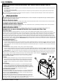
NAME PLATE
The Model Number and Serial Number of your machine are shown on the Nameplate on the machine. This information is needed when ordering repair parts for the machine.
Date of Manufacture “Date Code” is also marked on the Nameplate. For example, Date Code “A17” = January 2017.
Use the space below to note the Model Number and Serial Number of your machine for future reference.
MODEL No. __________________________________________________________
SERIAL No. __________________________________________________________
UNCRATE THE MACHINE
When the machine is delivered, carefully inspect the shipping packaging and the machine for damage. If damage is evident, save the shipping carton (if applicable) so that it can
be inspected. Contact the Advance Customer Service Department immediately to fi le a freight damage claim. Refer to the unpacking instruction sheet included with the machine to
remove the machine from the pallet.
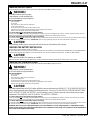
WARNING!
The Products sold with this Manual contain or may contain chemicals that are known to certain governments (such as the State of California, as
identifi ed in its Proposition 65 Regulatory Warning Law) to cause cancer, birth defects or other reproductive harm. In certain locations (including
the State of California) purchasers of these Products that place them in service at an employment job site or a publicly accessible space are
required by regulation to make certain notices, warnings or disclosures regarding the chemicals that are or may be contained in the Products at
or about such work sites. It is the purchaser’s responsibility to know the content of, and to comply with, any laws and regulations relating to the
use of these Products in such environments. The Manufacturer disclaims any responsibility to advise purchasers of any specifi c requirements that
may be applicable to the use of the Products in such environments.

ENGLISH / A-3
FORM NO. 56091013 - ES4000 - A-3
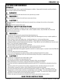
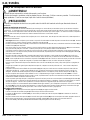
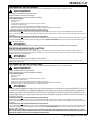
CAUTIONS AND WARNINGS
SYMBOLS
Advance uses the symbols below to signal potentially dangerous conditions. Always read this information carefully and take the
necessary steps to protect personnel and property.
DANGER !
Is used to warn of immediate hazards that will cause severe personal injury or death.
WARNING !
Is used to call attention to a situation that could cause severe personal injury.
CAUTION !
Is used to call attention to a situation that could cause minor personal injury or damage to the machine or other property.
Read all instructions before using.
GENERAL SAFETY INSTRUCTIONS
Specifi c Cautions and Warnings are included to warn you of potential danger of machine damage or bodily harm.
This machine is for commercial use, for example in hotels, schools, hospitals, factories, shops and offi ces other than normal
residential housekeeping purposes.
WARNING !
• This machine shall be used only by properly trained and authorized persons.
* This machine is not intended for use by persons (including children) with reduced physical, sensory or mental capabilities, or
lack of experience and knowledge.
* While on ramps or inclines, avoid sudden stops. Avoid abrupt sharp turns. Use low speed down ramps.
• Keep sparks, fl ame and smoking materials away from batteries. Explosive gases are vented during normal operation.
• Charging the batteries produces highly explosive hydrogen gas. Charge batteries only in well-ventilated areas, away from open
fl ame. Do not smoke while charging the batteries.
• Remove all jewelry when working near electrical components.
• Turn the key switch off (O) and disconnect the batteries before servicing electrical components.
• Never work under a machine without safety blocks or stands to support the machine.
• Do not dispense fl ammable cleaning agents, operate the machine on or near these agents, or operate in areas where fl ammable
liquids exist.
• Do not clean this machine with a pressure washer.
• Do not use for cleaning purposes on surfaces having a gradient exceeding that marked on the machine
• Observe the Gross Vehicle Weight, GVW, of the machine when loading, driving, lifting or supporting the machine.
CAUTION !
• This machine is not approved for use on public paths or roads.
• This machine is not suitable for picking up hazardous dust.
• When operating this machine, ensure that third parties, particularly children, are not endangered.
• Before performing any service function, carefully read all instructions pertaining to that function.
• Do not leave the machine unattended without fi rst turning the key switch off (O), removing the key and applying the parking
brake.
• Turn the key switch off (O) and remove the key, before changing the brushes, and before opening any access panels.
• Take precautions to prevent hair, jewelry, or loose clothing from becoming caught in moving parts.
• Use caution when moving this machine in below freezing temperature conditions. Any water in the solution, recovery or
detergent tanks or in the hose lines could freeze, causing damage to valves and fi ttings. Flush with windshield washer fl uid.
• The batteries must be removed from the machine before the machine is scrapped. The disposal of the batteries should be
safely done in accordance with your local environmental regulations.
• All doors and covers are to be positioned as indicated in the instruction manual before using the machine.
SAVE THESE INSTRUCTIONS
revised 1/13

A-4 / ENGLISH
A-4 - FORM NO. 56091013 - ES4000
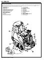
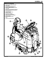
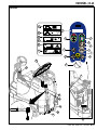
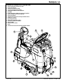
KNOW YOUR MACHINE
As you read this manual, you will occasionally run across a bold number or letter in parentheses - example: (2). These numbers refer to an item shown on these
pages unless otherwise noted. Refer back to these pages whenever necessary to pinpoint the location of an item mentioned in the text. NOTE: Refer to the
service manual for detailed explanations of each item illustrated on the next 3 pages.
1 Operator’s Seat
2 Seat Adjustment Knob
3 Emergency Stop
4 Control Circuit Circuit Breaker (10 Amp)
5 Drive Wheel Circuit Breaker (70 Amp)
6 Detergent Cartridge Access Cover
7 Battery Charger (optional)
8 Battery Charger Access Door
9 Drive Wheel
10 Drive Pedal, Directional/Speed
11 Front Roller Bumper
12 Brush Idler Removal Knob
13 Brush Deck
14 Debris Hopper
15 Vacuum Shoes
16 Solution Tank Drain Hose
17 Rear Wheel
18 Detergent Cartridge
19 Battery Compartment (under seat)
20 Solution Spray Jets

ENGLISH / A-5
FORM NO. 56091013 - ES4000 - A-5
KNOW YOUR MACHINE
21 Steering Wheel Tilt Adjust Knob
22 Control Panel
23 Solution Tank Fill Cover
24 Recovery Tank Cover
25 Vacuum Motor Filter Housing
26 Strainer Basket
27 Recovery Tank Shutoff Float
28 Recovery Tank Drain Hose
29 Recovery Hose
30 Dry Pick Up Connection
31 Accessory Port
32 Seat Prop-Rod
33 Rear Brush Access Panel
34 Machine Battery Connector
35 Solution Filter
36 Solution Shutoff Valve
37 Steering Wheel
38 Wet Pick Up Connection
35
36
21
22
23
24 25
26
27
28
32
34 29
30
31
33
37
38
revised 10/13

A-6 / ENGLISH
A-6 - FORM NO. 56091013 - ES4000
A
B
C
D
E
E1 E2 E3
E5
F
G
H
I
J
K
E6
E7 E8
E9
E10
E11
E4
E12
E13
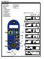
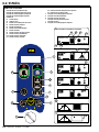
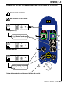
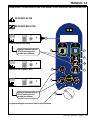
CONTROL PANEL
A Key Switch / Main Power
B Solution ON / OFF Switch
C Detergent ON / OFF Switch
D Sweep ON / OFF Switch
E LCD Display
E1 Hour Meter
E2 Fault Codes
E3 Solution Tank Level Indicator
E4 Transport Mode Indicator
E5 Detergent Indicator
E6 Detergent Ratio Indicator
E7 Battery Indicator
E8 Prespray Mode Indicator
E9 Maintenance Mode Indicator
E10 Restore Mode Indicator
E11 Sweep Mode Indicator
E12 Recovery Tank Full Indicator
E13 Low Voltage Cutout Indicator
F Extract ON / OFF Switch
G Maintenance Mode Switch
H Restoration Mode Switch
I Prespray Mode Switch
J Horn Switch
K Vacuum ON / OFF Switch
APPEARS FOR FIRST 10 SECONDS
APPEARS AFTER 10 SECONDS

ENGLISH / A-7
FORM NO. 56091013 - ES4000 - A-7
420 Ah, 20 Hr. Rate
BATTERIES
If your machine shipped with batteries installed do the following:
Check that the batteries are connected to the machine (34).
Turn ON the Key Switch (A) and check the Battery Indicator (E7). If the gauge is completely fi lled the batteries are ready for use. If the gauge is less than
full the batteries should be charged before use. See the “Charging The Batteries” section.
IMPORTANT!: IF YOUR MACHINE HAS AN ONBOARD BATTERY CHARGER REFER TO THE OEM PRODUCT MANUAL FOR INSTRUCTIONS
REGARDING SETTING THE CHARGER FOR BATTERY TYPE.
If your machine shipped without batteries installed do the following:
Consult your Authorized Advance dealer for recommended batteries.
Install the batteries by following the instructions below.
DO NOT install two 12 volt batteries in your machine. This affects the stability of the machine.
IMPORTANT!: IF YOUR MACHINE HAS AN ONBOARD BATTERY CHARGER REFER TO THE OEM PRODUCT MANUAL FOR INSTRUCTIONS
REGARDING SETTING THE CHARGER FOR BATTERY TYPE.
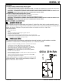
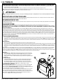
INSTALL THE BATTERIES
WARNING !
Use extreme caution when working with batteries. Sulfuric acid in batteries can cause severe injury if allowed to contact the skin or
eyes. Explosive hydrogen gas is vented from inside the batteries through openings in the battery caps. This gas can be ignited by
any electrical arc, spark or fl ame.
When Servicing Batteries...
* Remove all jewelry.
* Do not smoke.
* Wear safety glasses, a rubber apron and rubber gloves.
* Work in a well-ventilated area.
* Do not allow tools to touch more than one battery terminal at a time.
* ALWAYS disconnect the negative (ground) cable fi rst when replacing batteries to prevent sparks.
* ALWAYS connect the negative cable last when installing batteries.
CAUTION !
Electrical components in this machine can be severely damaged if the batteries are not installed and connected properly. Batteries
should be installed by Advance or by a qualifi ed electrician.
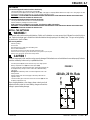
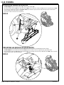
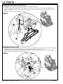
1 Turn the Key Switch (A) off (O) and remove the key. Then swing open the
Battery Compartment Cover (19) and set the Prop-Rod (32).
2 Using (2) people and an appropriate lifting strap, carefully lift the batteries into
the compartment tray exactly as shown. Refer to decal 56601416 battery
cable layout.
3 See Figure 1. Install battery cables as shown and tighten the nuts on the
battery terminals.
4 Install the battery boots and secure tightly to the battery cables with the
supplied tie straps.
5 Connect the battery pack connector to the machine connector (34) and close
the battery compartment cover.
When changing batteries or the charger, please contact your local
authorized service center for correct battery, charger and machine
settings to prevent battery damage.
FIGURE 1
revised 10/12

A-8 / ENGLISH
A-8 - FORM NO. 56091013 - ES4000
FILLING THE SOLUTION TANK (REQUIRED FOR BOTH SWEEP MODE AND EXTRACT MODE)
1 Read the cleaning chemical label and calculate the proper amount of chemical to mix for a tank that holds 28 US gallons (110 liters).
2 Open the Solution Tank Cover (23).
3 Fill the tank 1/3 full of water, add the cleaning chemical then fi ll the tank to 7.62cm(3 inches) from the top of the tank opening.
NOTE: The machine can either be used conventionally with detergent mixed in the tank or the detergent system can be used. When using the detergent
dispensing system do not mix detergent in the tank, plain water should be used.
CAUTION!
Use low-sudsing, liquid detergents designed for carpet extraction. Water temperature should not exceed 130 degrees Fahrenheit
(54.4 degrees Celsius).
BEFORE USING THE ES4000
Thorough vacuuming of the carpet to be cleaned is not necessary before using the ES4000 automatic extractor, due to the on-board sweeping broom and debris
hopper. The area should be cleaned in Sweep Mode before being cleaned in Extract Mode.
PRE-SPRAYING THE CARPET
Pre-spray spots and heavy traffi c areas before extracting. Use a hand-held bottle sprayer or a pressurized “Hudson” type sprayer. Mix the pre-spray according to
the chemical manufacturer’s directions.
PLAN FOR CLEANING
Before you begin extracting, look at the area to be cleaned and plan your work. Divide the space into sections. Overlap each pass 2 inches (5 cm).
DETERGENT SYSTEM PREPARATION AND USE (ONLY USED IN EXTRACT MODE)
COMMON INSTRUCTIONS:
Pressing and releasing the Detergent Switch (C) while in Restoration (H), Maintenance (G) or Prespray (I) mode will cause the detergent system to alternately turn
on and off. When the detergent system is ON, the detergent pump will be activated at a specifi c rate while the solution pump is running. The detergent pump will
turn OFF whenever the solution pump is not running or when the detergent system is turned OFF. Unless Prespray Mode (I) is selected, the detergent system
will be OFF by default each time the machine is powered up with the Key Switch (A). The detergent system will be selected by default when Prespray Mode (I)
is active. The Detergent ON / OFF Switch (C) is inactive when Sweep Power (D) is ON. The system should be purged of previous detergent when switching to a
different detergent. SERVICE NOTE: Move machine over fl oor drain before purging because a small amount of detergent will be dispensed in the process.
To Purge When Changing Chemicals:
1 Disconnect and remove the detergent cartridge.
2 Turn the Key Switch (A) ON. Press and hold the Detergent ON / OFF Switch (C) and the Solution ON / OFF Switch (B) for more than 2 seconds while the
controller is in any mode except standby to initiate a purge cycle. NOTE: Once activated the purge process takes 10 seconds. See illustration on next page
for Detergent System indicators. Normally one purge cycle is adequate to purge the system.
To Purge Weekly:
1 Disconnect and remove the detergent cartridge. Install and connect a Cartridge fi lled with clean water.
2 Turn the Key Switch (A) ON. Press and hold the Detergent ON / OFF Switch (C) and the Solution ON / OFF Switch (B) for more than 2 seconds while the
controller is in any mode except standby to initiate a purge cycle. NOTE: Once activated the purge process takes 10 seconds. See illustration on next page
for Detergent System indicators. Normally one purge cycle is adequate to purge the system.
When the Detergent Cartridge (18) is almost empty a Display Panel (E5) indicator will come on. The “Low Detergent” indicator will remain on until you reset the
system. Once this indicator comes on you should be able to simply pour an entire gallon bottle of detergent into the Cartridge to refi ll without worrying about
measuring. NOTE: Only reset the system when the cartridge is full. When switching cartridges, the “Low Detergent” indicator is only accurate if the replacement
cartridge is at the same level as the cartridge being replaced.
To Reset:
1 Turn the Key Switch (A) ON. Press and hold the Maintenance Mode Switch (G) and the
Restoration Mode Switch (H) for more than 2 seconds while the solution and detergent
are ON. The Detergent Reset Icon will display for 5 seconds. See illustration on next
page for Detergent System indicators.
Detergent Ratio:
1 The pre-programmed ratio can be adjusted. With the detergent system OFF, press and
hold the Detergent ON/OFF Switch (C) for 2 seconds. The detergent indicator will fl ash
and each press of the switch will cycle through the available ratios (1:64, 1:75, 1:100,
1:125, 1:150, 1:175, 1:200, 1:250). Once the desired ratio is displayed on the screen
(E6), stop and it will lock in after 5 seconds.
CARTRIDGE INSTRU CTIONS:
The Detergent Cartridge (18) is located behind the Detergent Cartridge Access Cover (6) in
the operator’s compartment. Fill the detergent cartridge with a maximum of 1.25 gallons (4.73
Liters) of detergent. SERVICE NOTE: Remove the detergent cartridge from the detergent
box prior to fi lling to avoid spilling detergent on the machine.
It is recommended that a separate cartridge be used for each detergent you plan to use. The
detergent cartridges have a white decal on them so you can write the detergent name on each
cartridge to avoid mixing them up. When installing a new cartridge, remove the Cap (AA) and
place the cartridge in the detergent box. Install the Dry Break Cap (BB) and detergent hose
as shown.
FIGURE 2

ENGLISH / A-9
FORM NO. 56091013 - ES4000 - A-9
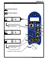
DETERGENT SYSTEM PREPARATION AND USE (ONLY USED IN EXTRACT MODE)
D
C
B
A
F
G
H
I
E
DETERGENT ENABLED
DETERGENT DISABLED
FULL (RESET)
Press and hold (G) & (H) for more
than 2 seconds to Reset.
LOW DETERGENT
PURGE
Press and hold (B) & (C) for more
than 2 seconds to Purge.
Detergent system is ON when indicator is ON.

A-10 / ENGLISH
A-10 - FORM NO. 56091013 - ES4000
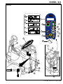
OPERATING THE MACHINE-SWEEP MODE
WARNING!
Be sure you understand the operator controls and their functions.
While on ramps or inclines, avoid sudden stops when loaded. Avoid abrupt sharp turns. Use low speed down hills. Clean only while
ascending (driving up) the ramp.
CAUTION!
Sweeping with a dry solution tank could reduce the life of the solution pump that powers the misting system.
FILLING THE SOLUTION TANK
While sweeping the ES4000 uses a misting system which sprays water into the airstream to dampen dust as it is drawn into the recovery tank. It is important
that there be water in the solution tank at all times during sweeping so dust does not escape the system. Refi ll the solution tank before sweeping whenever the
batteries have been recharged. Under normal conditions, a full solution tank should be adequate to supply the misting system through an entire battery cycle.
To Sweep...
Follow the instructions in preparing the machine for use section of this manual. Before cleaning in extraction mode the entire area should be cleaned in Sweep
Mode fi rst.
1 See Figure 3. While seated on the machine, adjust the steering wheel to a comfortable position using the Steering Wheel Tilt Adjust Knob (21). The seat can
be adjusted if necessary by tipping up the seat and using the adjustment knob (2).
2 Turn the Master Key Switch (A) ON (I). This will display the control panel indicator lights, reference the Battery Condition Indicator (E7) and Hour Meter (E1)
before proceeding.
3 To transport the machine to the work area, apply even pressure with your foot on the front of the Drive Pedal (10) to go forward or the rear of the pedal for
reverse. Vary the pressure on the foot pedal to obtain the desired speed.
4 If the machine was last used for extraction, follow the “To Switch to Sweep Mode…” instructions at the end of the “Operating the Machine-Extract Mode”
section. If the machine was last used in sweep mode simply press the Sweep ON / OFF Switch (D) to activate the sweep system.
5 After turning ON the Sweep System the deck will immediately lower to the fl oor. When the Drive Pedal (10) is engaged in forward or reverse, the solution
pump, brush motors, vacuum motors and the misting chamber valve will turn ON. NOTE: When the Drive Pedal (10) is in neutral, the solution pump, brush
motors and the misting chamber valve turn OFF. After 10 seconds, if the Drive Pedal (10) is not engaged, the vacuum motors turn OFF.
6 Begin cleaning by driving the machine forward in a straight line at a normal walking speed and overlap each path by 2-3 inches (50-75 mm).
If there is little or no fl uid entering the recovery tank, the solution tank may be empty. Refi ll the solution tank with water.
7 The recovery tank has an automatic fl oat shut-off (27) to prevent solution from entering the vacuum system when the recovery tank is full. When the fl oat
shut-off is activated, the control system will shut down the scrub, vacuum, solution and detergent systems. The Recovery Tank FULL Indicator (E12) will
display. To clear the display, cycle the Key Switch (A). When the fl oat closes, the recovery tank must be emptied. The machine will not pick up water
with the fl oat closed. NOTE: If the control repeatedly gives a full indication when the tank is not full, the automatic shut-off feature can be disabled, have a
qualifi ed service technician refer to the service manual to perform this function.
8 When the operator wants to stop cleaning or the recovery tank is full, press the Sweep ON / OFF Switch (D). The solution pump and misting chamber valve
will turn OFF immediately. The deck will raise to its upper limit and the brush motors will turn OFF. Once the deck is raised, the vacuum motors will turn OFF
after a 10 second delay.
9 Drive the machine to a designated waste water “DISPOSAL SITE” and empty the recovery tank. To empty, pull the Drain Hose (28) from its rear storage
area, then remove the plug (hold the end of the hose above the water level in the tank to avoid sudden, uncontrolled fl ow of waste water). Refi ll the solution
tank and continue cleaning.
To Switch to Extract Mode…
1 See Figure 3. Press the Sweep ON / OFF Switch (D) to turn OFF Sweep Mode.
2 Press Extract ON / OFF Switch (F) to activate Extract Mode.
3 The LCD Display (E) will display screen (E15) and the Horn will beep to indicate that the Recovery Hose (29) needs to be switched to the Wet Pick Up
Connection (38).
4 After switching the Recovery Hose (29) to the Wet Pick Up Connection (38) press the Extract ON / OFF Switch (F) to acknowledge the hose change. Press
the Extract ON / OFF Switch (F) again to turn ON Extract Mode
5 Refer to OPERATING THE MACHINE-EXTRACT MODE section for further operating instructions.

ENGLISH / A-11
FORM NO. 56091013 - ES4000 - A-11
FIGURE 3
10
2
21
24
27
28
29
38
31
A
B
C
DF
GH
IJ
K
E
E12
E13
E1
E7
E15

A-12 / ENGLISH
A-12 - FORM NO. 56091013 - ES4000
OPERATING THE MACHINE-EXTRACT MODE
WARNING!
Be sure you understand the operator controls and their functions.
While on ramps or inclines, avoid sudden stops when loaded. Avoid abrupt sharp turns. Use low speed down hills. Clean only while
ascending (driving up) the ramp.
To Extract...
Follow the instructions in preparing the machine for use section of this manual. Before cleaning in extraction mode the entire area should be cleaned in Sweep
Mode fi rst.
1 See Figure 4. While seated on the machine, adjust the steering wheel to a comfortable position using the Steering Wheel Tilt Adjust Knob (21). The seat can
be adjusted if necessary by tipping up the seat and using the adjustment knob (2).
2 Turn the Master Key Switch (A) ON (I). This will display the control panel indicator lights, reference the Battery Condition Indicator (E7) and Hour Meter (E1)
before proceeding.
3 To transport the machine to the work area, apply even pressure with your foot on the front of the Drive Pedal (10) to go forward or the rear of the pedal for
reverse. Vary the pressure on the foot pedal to obtain the desired speed.
4 If the machine was last used for sweeping, follow the “To Switch to Extract Mode…” instructions at the end of the “Operating the Machine-Sweep Mode”
section. If the machine was last used in extract mode simply press the Extract ON / OFF Switch (F), Maintenance Mode Switch (G), Restoration Mode
Switch (H) or the Prespray Mode Switch (I) to activate the extraction system. NOTE: Maintenance Mode (G) is the default setting upon initial startup. The
detergent system is OFF by default. It can be turned ON or OFF at any time by pressing the Detergent ON / OFF Switch (C).
5 If either the Maintenance Mode Switch (G) or the Restoration Mode Switch (H) is selected, the brush deck and vacuum shoes are automatically lowered to
the fl oor. When the Drive Pedal (10) is engaged forward, the solution pump, brush motors, vacuum motors and either the maintenance valve or the restore
valve are activated. NOTE: When the Drive Pedal (10) is in neutral or reverse, the solution pump, brush motors and either maintenance valve or the restore
valve turn OFF. After 10 seconds, if the Drive Pedal (10) is not engaged forward, the vacuum motors turn OFF.
If the Prespray Mode Switch (I) is selected, the brush deck is automatically lowered to the fl oor. When the Drive Pedal (10) is engaged forward, the solution
pump, brush motors and the restore valve are activated. The detergent pump will be activated at a specifi c rate. NOTE: When the Drive Pedal (10) is in
neutral or reverse, the solution pump, brush motors, detergent pump and restore valve turn OFF.
6 Begin cleaning by driving the machine forward in a straight line at a normal walking speed and overlap each path by 2-3 inches (50-75 mm). Turn the
Solution Switch (B) OFF prior to turns to ensure complete extraction of solution from carpet. Adjust when necessary the machine speed according to the
condition of the carpet.
If there is little or no fl uid entering the recovery tank, the solution tank may be empty. Refi ll the solution tank with water.
7 The recovery tank has an automatic fl oat shut-off (27) to prevent solution from entering the vacuum system when the recovery tank is full. When the fl oat
shut-off is activated, the control system will shut down the scrub, vacuum, solution and detergent systems. The Recovery Tank FULL Indicator (E12) will
display. To clear the display, cycle the Key Switch (A). When the fl oat closes, the recovery tank must be emptied. The machine will not pick up water
with the fl oat closed. NOTE: If the control repeatedly gives a full indication when the tank is not full, the automatic shut-off feature can be disabled, have a
qualifi ed service technician refer to the service manual to perform this function.
8 When the operator wants to stop cleaning or the recovery tank is full, press the Extract ON / OFF Switch (F). The solution pump, detergent pump and all
three solution solenoids will turn OFF immediately. The deck will raise to its upper limit and the brush motors will turn OFF. After a 3 second delay the
vacuum shoes will raise to the up position. Once the deck is raised, the vacuum motors will turn OFF after a 10 second delay.
9 Drive the machine to a designated waste water “DISPOSAL SITE” and empty the recovery tank. To empty, pull the Drain Hose (28) from its rear storage
area, then remove the plug (hold the end of the hose above the water level in the tank to avoid sudden, uncontrolled fl ow of waste water). Refi ll the solution
tank and continue cleaning.
NOTE: Make sure the Recovery Tank Cover (24) and the Recovery Tank Drain Hose (28) cap are properly seated or the machine will not pick-up water correctly.
When the batteries require recharging the Low Voltage Cutout Indicator (E13) will come on. The brushes, pumps and solenoids will turn OFF and the deck will raise up. Transport the
machine to a service area and recharge the batteries according to the instructions in the Battery section of this manual.
To Switch to Sweep Mode…
1 See Figure 4. Press the Extract ON / OFF Switch (F) to turn OFF Extract Mode.
2 Press Sweep ON / OFF Switch (D) to activate Sweep Mode.
3 The LCD Display (E) will display screen (E14) and the Horn will beep to indicate that the Recovery Hose (29) needs to be switched to the Dry Pick Up
Connection (30).
4 After switching the Recovery Hose (29) to the Dry Pick Up Connection (30) press the Sweep ON / OFF Switch (D) to acknowledge the hose change. Press
the Sweep ON / OFF Switch (D) again to turn ON Sweep Mode.
5 Refer to OPERATING THE MACHINE-SWEEP MODE section for further operating instructions.
USING ATTACHMENTS
Steps to follow in fi tting the machine with optional attachments for detail or upholstery cleaning.
1 Disconnect the recovery hose at the rear of the machine. Connect the coupler and hose from suitable wet pick-up tools to the recovery hose.
2 Attach the solution connection to the accessory port, located at the rear of the machine on the chassis. (An optional Wand Caddy Kit is available from
Advance).
3 Turn the Master Key Switch (A) ON while the machine driver seat is unoccupied, next press the Vacuum ON / OFF Switch (K). The vacuum motor will run
continuously until the switch is pressed again to turn it OFF. NOTE: If the control repeatedly gives a full indication when the tank is not full, the automatic
shut-off feature can be disabled, have a qualifi ed service technician perform this function.
SERVICE NOTE: Refer to the service manual for detailed functional descriptions of all controls and optional programmability.

ENGLISH / A-13
FORM NO. 56091013 - ES4000 - A-13
FIGURE 4
10
2
21
24
27
28
29
30
31
A
B
C
DF
GH
IJ
K
E
E12
E13
E1
E6
E7
E14

A-14 / ENGLISH
A-14 - FORM NO. 56091013 - ES4000
AFTER USE
1 When fi nished cleaning, press the Extract ON / OFF Switch (F) or the Sweep ON / OFF Switch (D), this will automatically raise, retract and stop all the
machine systems (brush, vacuum & solution). Then drive the machine to a service area for daily maintenance and review of other needed service up-keep.
2 To empty the solution tank, remove the Solution Tank Drain Hose (16) from its storage clamp. Direct the hose to a designated “DISPOSAL SITE” and remove
the plug. Rinse the tank with clean water.
3 To empty the recovery tank, pull the Recovery Tank Drain Hose (28) from its storage area. Direct the hose to a designated “DISPOSAL SITE” and remove
the plug (hold the end of the hose above the water level in the tank to avoid sudden, uncontrolled fl ow of waste water). Rinse the Recovery Tank with clean
water.
4 Remove the Brushes, rinse with warm water and remove any built-up string, hair or carpet fi bers.
5 Disconnect the Recovery Hose from the Recovery Tank and fl ush with warm water to wash any debris out of the Recovery Hose / Vacuum Shoe Assembly.
6 Remove the debris hopper and clean thoroughly. Remove from left or right side of machine by lifting hopper up and tilting it forward then pull out.
7 Check the maintenance schedule below and perform any required maintenance before storage.
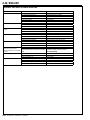
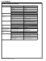
MAINTENANCE SCHEDULE
MAINTENANCE ITEM Daily Weekly Monthly Yearly
Charge Batteries X
Check/Clean Tanks & Hoses X
Check/Clean/ Power Brushes X
Check/Clean Vacuum Shoes X
Check/Clean Vacuum Shut-Off Float X
Check/Clean the vacuum motor foam fi lter(s) X
Empty Debris Hopper X
Clean Spray Nozzles X
Check Each Battery Cell(s) Water Level X
Inspect Brush Deck Skirts X
Inspect and clean Solution Filter X
Check Foot/ Parking Brake for Wear & Adjustment X
Purge the Detergent Injection System X
Lubrication - Grease Fittings X
* Check Carbon Brushes X
* Have Advance check the vacuum motor carbon motor brushes once a year or after 300 operating hours. The brush and drive motor carbon brushes check every
350 hours or once a year.
NOTE: Refer to the Service Manual for more detail on maintenance and service repairs.
8 Store the machine indoors in a clean dry place. Keep from freezing. Leave the tanks open to air them out.
9 Turn the Key Switch / Main Power (A) OFF (O) and remove the key.
VACUUM SHOE MAINTENANCE
Check the vacuum shoes daily, they can be removed to aid in cleaning, see “Removing the Vacuum Shoes”. Remove any built-up string, hair or carpet fi bers.
SPRAY NOZZLE MAINTENANCE
Remove the spray nozzles once a week, see “Removing the Spray Nozzles”. Soak the nozzles overnight in a vinegar and water solution to remove chemical
deposits. NOTE: DO NOT attempt to clean the nozzles by poking anything into them. This can damage the nozzle and affect the spray pattern.
LUBRICATING THE MACHINE
Once a month, pump a small amount of grease into each grease fi tting on the machine until grease seeps out around the bearings.
Grease fi tting locations are:
• Steering Wheel Shaft Universal joint
Once a month, apply light machine oil to lubricate the:
• Steering Chain
• General Pivot Points For the Brush Deck Linkage
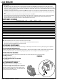
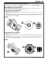
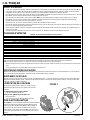
ELECTROMAGNETIC BRAKE
See Figure 5. The Drive Wheel Assembly (9) has a built in
electromagnetic brake that is engaged whenever the Key Switch (A) is
OFF or the Drive Pedal (10) is in the neutral position. This brake can
be manually over ridden if necessary by inserting a medium to large
screwdriver behind the Yoke (AA) as shown. This should only be done
in the event you need to push or pull the unit.
FIGURE 5
revised 12/11

ENGLISH / A-15
FORM NO. 56091013 - ES4000 - A-15
CLEANING THE VACUUM MOTOR FILTERS
Clean the vacuum motor fi lters daily with compressed air. For extremely dirty fi lters, wash with warm, soapy water and rinse thoroughly with clean water. Allow
the fi lters to dry completely before re-installing in the machine. MAINTENANCE NOTE: Keep a second set of fi lters on hand to use while fi rst set is drying.
POWER BRUSH MAINTENANCE
Check the brushes daily. Remove any built-up string, hair or carpet fi bers. Check the bristle length. Have a service technician change the brushes when the
brush bristles are worn to 1/2 inch (12.7 mm).
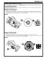
REMOVING THE FRONT BRUSH
1 See Figure 6. Turn the Key Switch (A) OFF.
2 Loosen the Brush Idler Removal Knob (12) on top of the idler assembly and remove the idler assembly. Slide the brush out of the brush deck housing.
3 To reinstall, slide the brush into the housing, lift slightly, push and turn until it seats. NOTE: Make sure Slots (AA) in end of Brush line up with and seat fi rmly
on Lugs (BB) on the Drive End Assembly. Re-install the idler assembly and tighten Knob (12).
FIGURE 6
REMOVING THE REAR BRUSH
1 See Figure 7. Turn the Key Switch (A) OFF.
2 Loosen the T-Knob holding the Rear Brush Access Panel (33) and slide the Panel (33). Slide the brush out of the brush deck housing.
3 To reinstall, slide the brush into the housing, lift slightly, push and turn until it seats. NOTE: Make sure Slots (AA) in end of Brush line up with and seat fi rmly
on Lugs (BB) on the Drive End Assembly. Re-install the idler assembly and tighten Knob (12).
FIGURE 7

A-16 / ENGLISH
A-16 - FORM NO. 56091013 - ES4000
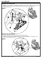
REMOVING THE VACUUM SHOES
1 See Figure 8. Turn the Key Switch (A) OFF and remove the Debris Hopper (14).
2 Disconnect the Vacuum Hose (AA) from the Vac Shoe (BB) and pull up on the gold Chain (CC). Slide the Vac Shoe (BB) out of the Shoe Support Weldment
(DD). NOTE: The procedure is the same for both vac shoes but the right side shoe must be removed before removing the left side shoe.
3 Reinstallation is reverse of removal.
FIGURE 8
REMOVING THE SPRAY NOZZLES
1 Turn the Key Switch (A) ON and Lower the Brush Deck (13) by pressing the Extract ON/OFF Switch (F).
2 See Figure 9. Remove the Maintenance Nozzle (EE) by turning counter-clockwise and then pulling straight off.
3 Remove the Restoration Nozzle (FF) by loosening Hose Clamp (GG) and disconnecting the solution hose and then loosening Nut (HH). The Nozzle
assembly can then be lifted straight up and off the deck.
FIGURE 9
FF
GG
EE
HH
revised 12/11

ENGLISH / A-17
FORM NO. 56091013 - ES4000 - A-17
CHARGING WET BATTERIES
Charge the batteries each time the machine is used or when the Battery Indicator (E7) is reading less than full.
WARNING!
Do not fi ll the batteries before charging.
Charge batteries in a well-ventilated area.
Do not smoke while servicing the batteries.
When Servicing Batteries...
* Remove all jewelry
* Do not smoke
* Wear safety glasses, rubber gloves and a rubber apron
* Work in a well-ventilated area
* Do not allow tools to touch more than one battery terminal at a time
* ALWAYS disconnect the negative (ground) cable fi rst when replacing batteries to prevent sparks.
* ALWAYS connect the negative cable last when installing batteries.
If your machine shipped with an onboard battery charger do the following:
Turn the Key Switch (A) OFF. Open the Battery Compartment (19 ) and the Battery Charger Access Door (8) for proper ventilation. Unwind the electrical cord from the side of the
onboard charger and plug it into a properly grounded outlet. Refer to the OEM product manual for more detailed operating instructions.
If your machine shipped without an onboard battery charger do the following:
Open the Battery Compartment (19) and set the Prop-Rod (32). Disconnect the batteries from the machine and push the connector from the charger into the Battery Pack Connector
(34). Follow the instructions on the battery charger. SERVICE NOTE: Make sure you plug the battery charger into the connector that attaches to the batteries.
CAUTION!
To avoid damage to fl oor surfaces, wipe water and acid from the top of the batteries after charging.
CHECKING THE BATTERY WATER LEVEL
Check the water level of the batteries at least once a week.
After charging the batteries, remove the vent caps and check the water level in each battery cell. Use distilled or demineralized water in a battery fi lling dispenser
(available at most auto parts stores) to fi ll each cell to the level indicator (or to 10 mm over the top of the separators). DO NOT over-fi ll the batteries!
CAUTION!
Acid can spill onto the fl oor if the batteries are overfi lled.
Tighten the vent caps. Wash the tops of the batteries with a solution of baking soda and water (2 tablespoons of baking soda to 1 liter of water).
CHARGING GEL (VRLA) BATTERIES
Charge the batteries each time the machine is used or when the Battery Indicator (E7) is reading less than full.
WARNING!
Charge batteries in a well-ventilated area.
Do not smoke while servicing the batteries.
When Servicing Batteries...
* Remove all jewelry
* Do not smoke
* Wear safety glasses, rubber gloves and a rubber apron
* Work in a well-ventilated area
* Do not allow tools to touch more than one battery terminal at a time
* ALWAYS disconnect the negative (ground) cable fi rst when replacing batteries to prevent sparks.
* ALWAYS connect the negative cable last when installing batteries.
CAUTION!
Your voltage regulated lead acid (VRLA) battery will deliver superior performance and life ONLY IF IT IS RECHARGED PROPERLY!
Under or overcharging will shorten battery life and limit performance. Be sure to FOLLOW PROPER CHARGING INSTRUCTIONS!
DO NOT ATTEMPT TO OPEN THIS BATTERY! If a VRLA battery is opened, it loses its pressure and the plates become oxygen
contaminated. THE WARRANTY WILL BE VOIDED IF THE BATTERY IS OPENED.
If your machine shipped with an onboard battery charger do the following:
Turn the Key Switch (A) OFF. Open the Battery Compartment (19) and the Battery Charger Access Door (8) for proper ventilation. Unwind the electrical cord from the side of the
onboard charger and plug it into a properly grounded outlet. Refer to the OEM product manual for more detailed operating instructions.
If your machine shipped without an onboard battery charger do the following:
Open the Battery Compartment (19) and set the Prop-Rod (32). Disconnect the batteries from the machine and push the connector from the charger into the Battery Pack Connector
(34). Follow the instructions on the battery charger. SERVICE NOTE: Make sure you plug the battery charger into the connector that attaches to the batteries.
IMPORTANT: Make sure you have an appropriate charger for use on Gel cell batteries. Use only “voltage-regulated” or “voltage-limited” chargers.
Standard constant current or taper current chargers MUST NOT be used. A temperature-sensing charger is recommended, as manual adjustments are
never accurate and will damage any VRLA battery.

A-18 / ENGLISH
A-18 - FORM NO. 56091013 - ES4000
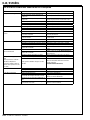
GENERAL MACHINE TROUBLESHOOTING
Problem Possible Cause Remedy
Poor water pick-up Recovery tank full Empty recovery tank
Recovery tank drain hose leak Secure drain hose cap or replace
Recovery tank cover gasket leak Replace gasket / Seat cover properly
Debris caught in vacuum shoes Clean vacuum shoes
Vacuum hose clogged Remove debris
Foam fi lter cover not seated Seat cover properly
Poor extracting performance Worn brushes Rotate or replace brushes
Wrong cleaning chemical Consult Advance
Moving machine too fast Slow down
Inadequate solution fl ow or no
solution Solution tank empty Fill solution tank
Solution lines, valves, fi lter, or spray jets clogged Flush lines and clean solution fi lter & spray jets
Solution control valve is in closed position Place control valve handle in open position
Solution solenoid valves Clean or replace valves
Machine does not run Emergency stop switch tripped Reconnect battery connectors
Operator seat safety switch Check for open circuit and replace
Main system controller Check for error fault codes (see service manual)
Tripped 10 Amp circuit breaker Check for electrical short circuit & reset
No FWD/REV wheel drive Drive system speed controller Check for error fault codes (see service manual)
Tripped 70 Amp circuit breaker Check for drive motor overload
Emergency stop switch tripped Reconnect battery connectors
Vacuum shuts off and display
shows Recovery Tank FULL
Indicator (E12) when recovery tank
is not full
Plugged vacuum hose(s) Clear debris
Vacuuming large amounts of water at a high travel
speed Slow down or disable auto shut-off feature
(see service manual)
Poor Sweeping Performance Debris Hopper Full Empty and clean hopper
Brushes worn Replace brushes
Bristles have taken a set Rotate brushes
No Detergent Flow Empty detergent cartridge Fill detergent cartridge
Plugged or kinked detergent fl ow line Purge system, straighten lines to remove any kinks
Dry seal cap on detergent cartridge not sealed Reseat dry seal cap
Detergent pump wiring disconnected or backwards Connect or reconnect wiring

ENGLISH / A-19
FORM NO. 56091013 - ES4000 - A-19
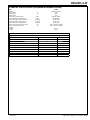
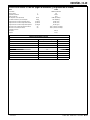
TECHNICAL SPECIFICATIONS (as installed and tested on the unit)
Model ES4000
Model No. 56344200 / 56344210
Voltage, Batteries V 24V
Battery Capacity Ah 238 Ah
Protection Grade IPX3
Sound Pressure Level (ISO 11201) dB(A) 65dB LpA, 3dB KpA
Gross Vehicle Weight / Transport Weight lbs(kg) 1447 lbs(656 kg)
Maximum Wheel Floor Loading (center front) psi / N/mm2 178.64 / 1.232
Maximum Wheel Floor Loading (right rear) psi / N/mm2 150.81 / 1.040
Maximum Wheel Floor Loading (left rear) psi / N/mm2 130.61 / 0.901
Vibrations at the Hand Controls (ISO 5349-1) m/s2 .22m/s2 (.044 m/s2 uncertainty)
Vibrations at the Seat (ISO 2631-1) m/s2 .02m/s2 (.004 m/s2 uncertainty)
Gradeability
Transport 16% (9°)
Cleaning 9% (5°)
Material Composition and Recyclability
Type % of machine weight % recyclable
Aluminum 1% 67%
Electrical / motors / engines - misc 18% 33%
Ferrous metals 39% 100%
Harnesses / cables 3% 75%
Liquids 0% 100%
Plastic - non-recyclable 6% 0%
Plastic - recyclable 6% 57%
Polyethylene 26% 93%
Rubber 1% 50%
revised 7/13

B-2 / ESPAÑOL
B-2 - FORM NO. 56091013 - ES4000
ÍNDICE
página
Introducción: .........................................................................................B-2
Precauciones y advertencias ................................................................B-3
Conozca su máquina ...................................................................B-4 - B-5
Panel de control ....................................................................................B-6
Preparación de la máquina para su uso
Instalación de las baterías ....................................................................B-7
Llenado del depósito de solución .........................................................B-8
Pulverizac ión previa de la moqueta ......................................................B-8
Planifi caci ón de la limpieza ..................................................................B-8
Preparación y uso del sistema de detergente .............................B-8 - B-9
Manejo de la máquina
Manejo de la máquina: modo de barrido ..................................B-10 - B-11
Manejo de la máquina: modo de extracción ............................B-12 - B-13
Uso de accesorios ..............................................................................B-12
revised 1/18
página
Después de la utilización ....................................................................B-14
Programa de mantenimiento ..............................................................B-14
Mantenimiento de la zapata de aspiración .........................................B-14
Mantenimiento de la boquilla de pulverización ...................................B-14
Lubricación de la máquina ..................................................................B-14
Freno electromagnético ......................................................................B-14
Limpieza de fi ltros del motor de aspiración ........................................B-15
Mantenimiento del cepillo eléctrico .....................................................B-15
Extracción del cepillo delantero ..........................................................B-15
Extracción del cepillo trasero ..............................................................B-15
Extracción de las zapatas de aspiración ............................................B-16
Cómo retirar las boquillas de pulverización ........................................B-16
Recarga de las baterías .....................................................................B-17
Comprobación del nivel de electrolitos de las baterías ......................B-17
Resolución de problemas ...................................................................B-18
Especifi caciones técnicas ...................................................................B-19
INTRODUCCIÓN
Este manual le ayudará a obtener el máximo rendimiento de su Extractor sobre ruedas Advance. Léalo con atención antes de utilizar la máquina.
Nota: Los números que aparecen en negrita entre paréntesis indican elementos ilustrados en las páginas 4-6.
Este producto está destinado exclusivamente a uso comercial.
COMPONENTES Y SERVICIO
Las reparaciones, cuando sean necesarias, deben ser realizadas por su Centro Autorizado de Servicio Advance, que utiliza personal de servicio formado en
fábrica y lleva un inventario de las piezas de repuesto y accesorios Advance originales.
Llame al DISTRIBUIDOR ADVANCE que se indica a continuación para lo referente a piezas de repuesto y servicio. Por favor, especifi que el modelo y el número
de serie cuando hable de su máquina.
MODIFICACIONES
Las modifi caciones y los agregados a la máquina de limpieza que afecten su capacidad y su funcionamiento seguro no serán realizados por el cliente o el usuario
sin la autorización previa y por escrito de Nilfi sk Inc. Las modifi caciones que no cuenten con la aprobación correspondiente anularán la garantía de la máquina y
harán que el cliente sea responsable de cualquier accidente resultante.
PLACA DE IDENTIFICACIÓN
El Número de modelo y Número de serie de la máquina se indican en la placa de identifi cación instalada en la misma. Esta información es necesaria a la hora de
solicitar repuestos para la máquina.
La fecha de fabricación, “código de fecha”, también está marcado en la placa de identifi cación. Por ejemplo, código de fecha “A17” = enero de 2017.
Utilice el espacio situado más adelante para anotar el número de modelo y el número de serie de la máquina para futuras consultas.
Núm. de MODELO _____________________________________________
Núm. de SERIE ________________________________________________
DESEMBALAJE DE LA MÁQUINA
Cuando reciba la máquina, examine con atención la caja del embalaje y la máquina, con el fi n de comprobar si existe algún daño. Si observa algún daño, guarde
la caja de embalaje (si procede) para que se pueda inspeccionar. Póngase en contacto inmediatamente con el Departamento de Servicio al Cliente de Advance
para presentar una reclamación por daños en transporte. Consulte la hoja de instrucciones de desembalaje incluida con la máquina para sacar la máquina del
palet. ¡ADVERTENCIA!
Los Productos a la venta en este Manual contienen, o pueden contener, productos químicos reconocidos por algunos gobiernos (como el Estado de California,
según lo indica en su Proposición 65, Ley de Advertencia Regulatoria) como causantes de cáncer, defectos de nacimiento u otros daños reproductivos. En
algunas jurisdicciones (incluido el Estado de California), los compradores de estos Productos que los coloquen en servicio en un emplazamiento laboral o en
un espacio de acceso público tienen la obligación regulatoria de realizar determinados avisos, advertencias o divulgaciones respecto de los productos químicos
contenidos o posiblemente contenidos en los Productos utilizados en tal lugar. Es la responsabilidad del comprador conocer y cumplir con todas las leyes y
reglamentaciones relacionadas con el uso de estos Productos en tales entornos. El Fabricante niega toda responsabilidad de informar a los compradores sobre
requisitos específi cos que pueden regir el uso de los Productos en tales entornos.
La page est en cours de chargement...
La page est en cours de chargement...
La page est en cours de chargement...
La page est en cours de chargement...
La page est en cours de chargement...
La page est en cours de chargement...
La page est en cours de chargement...
La page est en cours de chargement...
La page est en cours de chargement...
La page est en cours de chargement...
La page est en cours de chargement...
La page est en cours de chargement...
La page est en cours de chargement...
La page est en cours de chargement...
La page est en cours de chargement...
La page est en cours de chargement...
La page est en cours de chargement...
La page est en cours de chargement...
La page est en cours de chargement...
La page est en cours de chargement...
La page est en cours de chargement...
La page est en cours de chargement...
La page est en cours de chargement...
La page est en cours de chargement...
La page est en cours de chargement...
La page est en cours de chargement...
La page est en cours de chargement...
La page est en cours de chargement...
La page est en cours de chargement...
La page est en cours de chargement...
La page est en cours de chargement...
La page est en cours de chargement...
La page est en cours de chargement...
La page est en cours de chargement...
La page est en cours de chargement...
La page est en cours de chargement...
La page est en cours de chargement...
La page est en cours de chargement...
La page est en cours de chargement...
La page est en cours de chargement...
-
 1
1
-
 2
2
-
 3
3
-
 4
4
-
 5
5
-
 6
6
-
 7
7
-
 8
8
-
 9
9
-
 10
10
-
 11
11
-
 12
12
-
 13
13
-
 14
14
-
 15
15
-
 16
16
-
 17
17
-
 18
18
-
 19
19
-
 20
20
-
 21
21
-
 22
22
-
 23
23
-
 24
24
-
 25
25
-
 26
26
-
 27
27
-
 28
28
-
 29
29
-
 30
30
-
 31
31
-
 32
32
-
 33
33
-
 34
34
-
 35
35
-
 36
36
-
 37
37
-
 38
38
-
 39
39
-
 40
40
-
 41
41
-
 42
42
-
 43
43
-
 44
44
-
 45
45
-
 46
46
-
 47
47
-
 48
48
-
 49
49
-
 50
50
-
 51
51
-
 52
52
-
 53
53
-
 54
54
-
 55
55
-
 56
56
-
 57
57
-
 58
58
-
 59
59
-
 60
60


Nilfisk ES4000 Le manuel du propriétaire
- Catégorie
- Machine à plancher
- Taper
- Le manuel du propriétaire
dans d''autres langues
- English: Nilfisk ES4000 Owner's manual
- español: Nilfisk ES4000 El manual del propietario
Documents connexes
Autres documents
-
Nilfisk-Advance CR 1200 Instructions For Use Manual
-
Nilfisk-Advance America BRX 700 Series Manuel utilisateur
-
-
Nilfisk-Advance Hydro-Retriever 3800 Instructions For Use Manual
-
Windsor Chariot 3 iExtract 26 DUO Le manuel du propriétaire
-
-
Windsor Chariot 3 iScrub 26 10061500 Operating Instructions Manual
-
Smithco Sweep Star 60-QUAD Le manuel du propriétaire