Eurotherm 3200 Le manuel du propriétaire
- Taper
- Le manuel du propriétaire

3200 Series Controllers -
Installation
Models 3216, 3208, 32h8 and 3204
This User Guide describes wiring, safety,
and operation in Operator Levels 1 and 2.
For further details an Engineering Manual,
Part No HA028651, and other related
handbooks can be downloaded from
www.eurotherm.co.uk.
Serie 3200
Temperaturregler - Installation
Für die Modelle 3216, 3208, 32h8
und 3204
Die Anleitung beschreibt die Verdrahtung,
Sicherheit und Bedienung in den Bedien-
ebenen 1 und 2. Für weitere Details können
Sie das Konfigurationshandbuch, Best.nr.
HA028651GER und andere Handbücher von
www.eurotherm.de herunterladen.
c
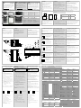
Latching ears Clips de
verrouillage
Außenklammern
d
IP65 Sealing
Gasket
Joint d’étanchéité
IP65
IP65 Dichtung
e
Panel retaining
clips
Clip de montage Rückhalteklammern
f
Sleeve Manchon Gehäuse
3216
32h8
A
c
A
B
C D
B
c
d
e
e
f
f
A
48mm (1.89inch)
C
12.5mm (0.5 inch)
B
96mm (3.78 inch)
D
90mm (3.54 inch)
e
e
Also supplied Également fourni
Ebenfalls
1 x 2.49Ω resistor
1 résistance 2,49Ω 1 X 2,49Ω Widerstand
2 x Snubber 2 X circuit RC 2 X RC Glied
3208 3204
d
3200 Régulateurs de
température - Installation
Modèles 3216, 3208, 32h8 et 3204
Ce guide de l’utilisateur décrit
l’installation, le câblage et les règles de
sécurité de niveaux 1 et 2. Pour plus de
détails, consultez le manuel d’engineering
HA028651FRA, téléchargeable sur notre
site : www.eurotherm.tm.fr.
GER FRA ENG
HA029714EFG/5 CN26446 06/10
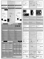
Parts Supplied and Dimensions Pièces Fournies et Dimensions Lieferumfang und Abmessungen
Verdrahtung
Kabelquerschnitt
Die Schraubklemmen auf der Regler
Rückseite sind für Kabelquerschnitte von 0,5
bis 1,5 mm
2
vorgesehen (16 bis 22AWG). Die
Klemmenleisten sind jeweils mit einer
Kunststoffabdeckung zum Schutz vor
Berührung versehen. Achten Sie beim
Anziehen der Schrauben darauf, dass das
Drehmoment 0,4 Nm nicht übersteigt.
Wiring
Wire Sizes
The screw terminals accept wire sizes
from 0.5 to 1.5 mm (16 to 22AWG).
Hinged covers prevent hands or metal
making accidental contact with live
wires. The rear terminal screws should
be tightened to 0.4Nm (3.5lb in).
Câblage
Diamètres de fil
Les borniers à vis acceptent les fils de
0,5 à 1,5 mm (16 à 22AWG). Les
capots articulés évitent tout contact
accidentel avec les fils sous tension.
Les vis des borniers arrière sont à
serrer à 0,4 Nm.
B(
-
)
AA
AB
AC
HD
HE
HF
CT
C
LA
VI
V+
V-
1A
1B
2A
2B
LB
LC
3A
3B
3C
3D
L
N
+ +
-
-
+ NO
-
C
-
-
+ +
3208 3204
-
+
2.49
Ω
-
+
+
-
c
d
d
e
f
g
A(+)
COM
h
i
h
j
k
-
-
- -
AA
AB
AC
VI
V+
V-
1A
1B
2A
2B
L
N
CT
C
LA
HD
HE
HF
+ +
+ +
3216
-
+
2.49
Ω
-
+
c
d
d
f
g
h
j
k
B(
-
)
- + - +
-
+
N L 3D
-
-
+
LA
2.49
Ω
+
32h8
-
+
COM
A(+)
3C
3B
3A
LC
LB 2B
2A
1B
1A
C CT
HF HE HD
AC AB AA
V+ VI
V
-
c
d
d
e
f
g
h
i
j
k
- + - +
h
Logik Schließkontakteingang (nur OP1)
• Nicht von Fühlereingang isoliert.
• Ausgang EIN Status: 12 Vdc bei 40 mA
max
• Ausgang AUS Status: <300 mV,
<100 μA
• Bestellcodierung D nicht von
Fühlereingang isoliert. Bestellcodierung
C (nur OP2) isoliert 240 Vac.
• Softwarekonfigurierbar: 0-20 mA oder 4-
20 mA.
• Max. Leitungswiderstand: 500Ω
• Isolierter Ausgang 240 V AC
• Kontakt Nennwert: 2 A, 264 V AC
ohm’sch
Die Ausgänge können Logik (SSR
gesteuert), Relais oder mA DC sein.
Zusätzlich können sie den Logikausgang 1
als Schließkontakteingang verwenden
Für Funktionen siehe Quick Start Code
• Nicht von Fühlereingang isoliert.
• Schalten: 12 Vdc bei 40 mA max
• Kontakt öffnen > 500 Ω.
• Kontakt schließen < 150 Ω
Relaisausgang (Form A, Schließer)
Triacausgang
Logikausgang (SSR gesteuert)
DC Ausgang
• Isolierter Ausgang 240 Vac
• Nennwerte: 0,75 Aeff, 30 bis
264 Vac ohm’sch
Ausgang 1/2 (OP1) / (OP2)
Ces sorties peuvent être de type logique
(commande de contacteur), relais ou mA dc.
La sortie logique 1 peut être utilisée aussi
comme entrée contact sec.
Pour les fonctions voir le Code Rapide.
Relais (Forme A, normalement ouvert)
• Non isolée par rapport à l'entrée capteur
• Commutation : 12 Vdc à 40mA maxi
• Contact ouvert > 500 Ω.
• Contact fermé < 150 Ω
• Sortie isolée 240 Vac
• Calibre : 0,75 Aeff, de 30 à 264 Vac
résistif
Sortie Logique (commande relais statique
SSR)
Sortie Analogique
Entrée logique contacts (OP1 seulement)
• Non isolée par rapport à l'entrée du
capteur
• Sortie Etat actif (ON) : 12 Vdc à 40 mA
maxi
• Sortie Etat non actif (OFF) : <300 mV,
<100μA
• Code de commande D non isolée par
rapport à l'entrée du capteur. Code de
commande C (OP2 seulement) isolée
240Vac.
• Configurable: par Logiciel 0-20 mA ou 4-20
mA
• Résistance de charge maxi. : 500 Ω
• Sortie isolée 240Vac
• Pouvoir de coupure : 2 A 264 Vac
résistive
Sortie 1/2 (OP1) / (OP2)
Sortie Triac
Output 1/2 (OP1) / (OP2)
• Not isolated from the
sensor input
• Switching: 12Vdc at
40mA max
• Contact open > 500Ω.
• Contact closed <150Ω
Triac Output
Logic (SSR drive) Output
DC Output
Contact Closure Input (OP1 only)
• Not isolated from the
sensor input
• Output ON state:
12Vdc at 40mA max
• Output OFF state:
<300mV, <100μA
• Order code D non
isolated from the sensor
input. Order code C
(OP2 only) isolated
240Vac.
• Software configurable: 0-
20mA or 4-20mA.
• Max load resistance:500Ω
• Isolated output 240Vac
• Rating: 0.75A rms, 30 to
264Vac resistive
• Isolated output 240Vac
• Contact rating: 2A
264Vac resistive
OP1
/2
1/2A
1/2B
OP1 may be configured as input or output.
Outputs can be logic (SSR drive), relay, or
mA dc.
Input is contact closure.
For functions see Quick Start Code.
Relay (Form A, normally open)
OP1
/2
1/2A
1/2B
OP1
/2
1/2A
1/2B
OP1
/2
1/2A
1/2B
OP1
1A
1B
d
6. Options Options Optionen
XXX
Not fitted Non équipé Keine
4XL
EIA 485 & Digital
input A
EIA 485 & Entrée
logique A
EIA 485 &
Digitaleingang A
2XL
EIA232 & digital
input A
EIA232 & Entrée
logique B
EIA232 &
Digitaleingang B
4CL
EIA485, CT & Dig
in A
EIA485, CT &
Entrée logique A
EIA485, CT &
Digitaleingang A
2CL
EIA232, CT & Dig
in A
EIA232, CT &
Entrée logique A
EIA232, CT &
Digitaleingang A
XXL
Digital input A Entrée logique A Digitaleingang A
XCL
CT & Digital input
A
CT & Entrée
logique A
CT & Digitaleingang
A
RCL
Remote SP,
CT and
Logic IP
Consigne externe,
entrée logique
Externer SP und
Logikeingang
6XX
Comms 4-wire
EIA422/485 (3216
only)
Comms 4-fils
EIA422/485 (3216
seulement)
4-Leiter RS485
Comms (nur 3216)
11 Certificates Certificats Zertifikate
XXXXX
None Aucun Kein
CERT1
Conformity
Conformité Konformität
CERT2
Factory
calibration
Cal usine Werkskalibrierung
13. Specials
Number
Numéros spéciaux
Special Nummer
XXXXX None Aucun Kein
RES250
250Ω ; 0-5Vdc OP
RES500
500Ω ; 0-10Vdc OP
7. Fascia colour/type
Couleur plastron Frontfarbe/ Typ
G
Green Vert Grün
S
Silver Argent Silber
W
Wash down fascia Face avant étanche
Abwasch-bar
10. Warranty Garantie Garantie
XXXXX
Standard Standard Standard
WL005
Extended 2 ans
12
Custom Label Etiquette
personnalisée
Kundenlabel
XXXXX
None Aucun Kein
8/9 Language
Product/Manual
Langue Produit
/Manuel
Sprache
Produkt/Anleitung
ENG
English Anglais Enlisch
FRA
French Français Französisch
GER
German Allemand Deutsch
ITA
Italian Italien Italienisch
SPA
Spanish Espagnol Spanisch
4. 3208/h8/04
OP1
OP2
OP3
L R R X
R R R X
L L R X
L R D X
R R D X
D D D X
L L D X
L D D
D R D X
L * T * R * X
T * T * R * X
L * T * D * X
T * T * D * X
4. 3216
OP1
OP2
L X X X
L R X X
R R X X
L L X X
L D X X
D D X X
D R X X
R C X X
L C X X
D C X X
L * T * X X
T * T * X X
3. Power Supply
Alimentation Versorgung
VL
24Vac/dc
VH
100–240Vac
2. Function Fonction Funktion
CC
Controller Régulateur Regler
CP
Programmer Programmateur Programmgeber
VC
Valve controller Régulateur
Commande
servomoteur
Schrittregler
VP
Valve
programmer
servomoteur-
Programmateur
VP
Programmgeber
5.
OP4
(AA Relay) (AA Relais) (AA Relais)
X
Disabled Non équipé Gesperrt
R
Relay
(Form C)
Relais
(Form C)
Relais (Forme C)
1. Model Modèle Modell
3216
1/16 DIN
3208
1/8 DIN vertical
vertical vertikale
32h8
1/8 DIN
horizontal
horizontal horizontale
3204
1/4 DIN
1 2 3 4 5 6 7 8 9 10 11 12 13
Order Code Code de commande Bestellcodierung
* Not available with low voltage supply.
* Non disponible avec alimentation basse tension.
* Triac ist mit Kleinspannungsoption nicht verfügbar.
L Logic Logique Logik
R Relay Relais Relais
T Triac Triac Triac
D 0-20mA 0-20mA 0-20mA
C Isolated 0-20mA
Isolée 0-20mA Isolierter 0-
20mA
H
To Remove the Controller from its
Sleeve
Ease the latching ears
c outwards and
pull the controller forward.
When plugging back in ensure that the
latching ears click into place to maintain
the IP65 sealing
Installation
1.Cut out the panel to the size shown.
2.Fit the IP65 sealing gasket behind the
front bezel of the controller
3.Insert the controller in its sleeve
through the cut-out.
4.Spring the panel retaining clips into
place. Secure the controller in
position by holding it level and
pushing both retaining clips forward.
5.Peel off the protective cover from the
display
Installation Installation
1. Bereiten Sie den Schalttafelausschnitt nach
der untenstehenden Abbildung vor.
2. Wenn nötig, montieren Sie die IP65
Dichtung hinter den Frontrahmen des
Reglers.
3. Stecken Sie den Regler in den
Schalttafelausschnitt.
4. Bringen Sie die Halteklammern an ihren
Platz. Zum Sichern des Reglers halten Sie
das Gerät in Position und schieben Sie beide
Klammern gegen den Schalttafelausschnitt.
5. Lösen Sie die Schutzfolie von der Anzeige
1. Effectuer la découpe dans le panneau
aux dimensions indiquées
2. Monter le joint d'étanchéité IP65 derrière
la face avant du régulateur
3. Engager le régulateur dans la découpe
4. Positionner les clips de fixation. Maintenir
le régulateur et presser les clips de
fixation vers l'avant
5. Retirer le film de protection de l'afficheur
Panel Cut-out and Recommended
Minimum Spacing (Not to scale)
E 45mm (- 0.0 + 0.6)
1.77inch (-0.00, +0.02)
G 38mm (1.5in)
F 92mm (- 0.0 + 0.8)
3.62 inch (-0.00, +0.03)
H 10mm (0.4in)
Dimensions des découpes du panneau et
Espacements minimum entre les régulateurs.
(
Echelle libre
)
Schalttafelausschnitte und
Minimalabstände zwischen Reglern
(Nicht maßstabsgerecht)
32h8
G
F
3208
3204
E
E
E
3216
E
Reglerwechsel
Durch Auseinanderziehen der Außenklammern
c und nach vorne ziehen des Reglers können
Sie das Gerät aus dem Gehäuse entnehmen.
Wenn Sie das Gerät zurück in das Gehäuse
stecken, versichern Sie sich, dass die
Außenklammern einrasten.
Pour retirer le régulateur de son manchon
Le régulateur peut être sorti de son manchon,
par traction vers l'avant après déblocage des
clips de verrouillage c.
Au remontage dans son manchon, s'assurer
que les clips s’enclenchent correctement, afin
que le niveau de protection IP65 soit maintenu.
F F
• High voltage supply:
100 to 240Vac, -15%, +10%,
48 to 62 Hz
• Low voltage supply:
24Vac/dc, -15%, +10%
• Recommended external fuse
ratings are as follows:-
For 24 V ac/dc, fuse type: T rated
2A 250V
For 100-240Vac, fuse type: T
rated 2A 250V.
!
Achten Sie auf die richtige
Spannungsversorgung für
Ihren Regler.
1. Bevor Sie das Gerät an die Versorgungs-
spannung anschließen, überprüfen Sie,
dass die Netzspannung der Geräte-
spannung (siehe Geräteaufkleber)
entspricht.
2. Verwenden Sie nur Kupferleitungen.
3. Der Eingang der Spannungsversorgung ist
intern nicht abgesichert. Bauen Sie eine
externe Sicherung oder einen
Unterbrechungskontakt ein.
4. Bei 24 V ist die Polarität unwichtig.
Sicherheitsanforderungen für permanent
angeschlossene Anlagenbauteile:
• Die Schaltschrankinstallation muss einen
Schalter oder Unterbrechungskontakt
beinhalten.
• Dieses Bauteil sollte in der Nähe der
Anlage und in direkter Reichweite des
Bedieners sein.
• Kennzeichnen Sie dieses Bauteil als
trennende Einheit.
Anmerkung: Sie können einen Schalter oder
Trennkontakt für mehrere Geräte verwenden
Regler Spannungsversorgung
• Spannungsversorgung:
100-240 Vac, -15%, +10%,
48 bis 62 Hz
• Kleinspannung:
24 Vac/dc, -15%, +10%
• Externe Sicherungen:
Für 24 Vac/dc Sicherung Typ T, 4A
250V.
Für 100/240 Vac Sicherung Typ T, 1
A 250 V.
!
Vérifier la compatibilité du
régulateur avec l'alimentation
réseau
1. Avant de connecter le régulateur au
réseau électrique, vérifier que la tension
de ligne correspond à la description
figurant sur l'étiquette d'identification.
2. Utiliser uniquement des conducteurs en
cuivre
3. L'entrée d'alimentation n'est pas
protégée par un fusible. La protection
doit donc être assurée par le client.
4. En 24 V, la polarité n'est pas importante
Conditions de sécurité pour les
équipements connectés en permanence :
• Un interrupteur/ disjoncteur sera inclus
dans l'installation
• Il devra être situé à proximité de
l'équipement et à portée de l'opérateur.
• Il sera clairement identifié comme
dispositif de sectionnement de
l'équipement.
Note : il est possible d'utiliser un seul
interrupteur/ disjoncteur pour plusieurs
instruments.
Alimentation électrique du
régulateur
• Alimentation haute tension :
100 à 240 Vac, -15%, +10%,
48 a 62 Hz
• Alimentation basse tension :
24 V ac/dc, -15%, +10%
• Calibre recommandé pour les fusibles
externes:
Pour 24 V ac/dc, fusible : T, 2 A 250 V
Pour 100-240 Vac, fusible: T, 2 A 250 V
!
Ensure that you have
the correct supply for
your controller
1.
Check order code of the controller
supplied
2.
Use copper conductors only.
3.
The power supply input is not fuse
protected. This should be provided
externally.
4.
For 24V the polarity is not important.
Safety requirements for permanently
connected equipment state:
• A switch or circuit breaker shall be
included in the building installation
• It shall be in close proximity to the
equipment and within easy reach of
the operator
• It shall be marked as the
disconnecting device for the
equipment.
Note: a single switch or circuit breaker
can drive more than one instrument.
Controller Power Supply
Phas
Neutral
L
N
24Vac oder dc
24
24
c
L
N
L
N
24
24
24
24
Line
Neutral
Li
g
ne
Neutr
e
24Vac o
u
dc
24Vac
or
dc
La page est en cours de chargement...

Manufacturing Address
U.K. Worthing
Eurotherm Ltd
T (+44) 1903 268500
www.eurotherm.co.uk
© Copyright Eurotherm LtdTM 2009
All rights are strictly reserved. No part of
this document may be reproduced,
modified or transmitted in any form by any
means, nor may it be stored in a retrieval
system other than for the purpose to act as
an aid in operating the equipment to which
the document relates, without the prior
written permission of Eurotherm.
Eurotherm pursues a policy of continuous
development and product improvement.
The specification in this document may,
therefore, change without notice. The
information in this document is given in
good faith, but it is intended for guidance
only. Eurotherm will accept no
responsibility for any loses arising from
errors in this document.
Hersteller Adresse
U.K. Worthing
Eurotherm Ltd
T (+44) 1903 268500
www.eurotherm.co.uk
© 2009 Eurotherm Deutschland GmbH
Alle Rechte vorbehalten.
Vervielfältigung, Weitergabe oder
Speicherung in jeglicher Art und Weise
ist nur mit vorheriger schriftlicher
Zustimmung durch Eurotherm
Deutschland GmbH gestattet.
Technische Änderungen vorbehalten.
Wir übernehemen keine Haftung
daraus.
Adresse Fabrication
U.K. Worthing
Eurotherm Ltd
T (+44) 1903 268500
www.eurotherm.co.uk
© Copyright Eurotherm LtdTM 2009
Tous droits réservés. Aucune partie du
présent document ne peut être reproduite,
stockée sur un système d’extraction ou
transmise sous quelque forme que ce soit,
quels que soient les moyens, sans le
consentement écrit préalable du détenteur
des droits d’auteur.
Eurotherm se réserve le droit de modifier les
spécifications de ses produits, le cas échéant
sans préavis. Bien que tous les efforts aient
été faits pour assurer l’exactitude des
informations contenues dans le présent
manuel, il n’est pas garanti ou certifié par
Eurotherm que la description du produit soit
complète ou à jour.
General Notes about Relays and
Inductive Loads
High voltage transients may occur when
switching inductive loads such as some
contactors or solenoid valves. These may
affect the performance of the instrument.
For this type of load it is recommended
that a ‘snubber’ is connected across the
normally open relay contact. This is a
series connected resistor/capacitor
(typically 15nF/100Ω). It will also prolong
the life of the relay contacts.
A snubber should also be connected
across the output terminal of a triac
output to prevent false triggering under
line transient conditions.
!
When the relay contact is open,
or it is connected to a high impedance
load, it passes a current (typically 0.6mA
at 110Vac and 1.2mA at 240Vac). You
must ensure that this current will not hold
on low power electrical loads. If the load
is of this type the snubber should not be
connected.
Remarque générale sur les relais et les
charges inductives
Des transitoires à haute tension risquent
d'apparaître à la commutation des charges
inductives (contacteurs ou électrovannes par
ex.). Ces transitoires peuvent occasionner
des perturbations susceptibles de nuire au
bon fonctionnement de l'instrument. Pour ce
type de charge, il est recommandé de
protéger le contact travail du relais de
commutation avec un “circuit RC”. Le circuit
RC recommandé se compose d'une
résistance/condensateur connectés en série
(généralement 15 nF/100 Ω). Ce montage
permet également de prolonger la durée de
vie des contacts du relais. Un circuit RC
devrait aussi être connecté entre les bornes
de la sortie Triac pour prévenir d’un
déclenchement intempestif en cas de
conditions de transitoires
!
Lorsque le contact du relais est
ouvert ou qu'il est connecté à une charge à
grande impédance, le circuit RC laisse passer
un courant résiduel (généralement de 0,6
mA à 110 V ac et de 1,2 mA à 240 V ac). Il
appartient à l’utilisateur de s’assurer que ce
courant ne suffit pas à maintenir l’énergie sur
une charge électrique. Dans ce cas le circuit
RC ne devra pas être installé.
Allgemeine Anmerkungen über Relais
und induktive Lasten
Beim Schalten von induktiven Lasten, wie
z. B. einigen Kontaktgebern oder
Magnetventilen, kann es zu Störspitzen
im Hochspannungsbereich kommen.
Durch die internen Kontakte können
diese Spitzen Störungen verursachen, die
die Funktion des Geräts beeinträchtigen.
Für diese Lastart benötigen Sie ein RC-
Glied über dem schaltenden Relais-
kontakt. Das RC-Glied besteht aus einem
15 nF Kondensator in Serie mit einem
100 Ω Widerstand. Dieses RC-Glied
erhöht außerdem die Lebensdauer des
Kontaktes.
!
Bei geöffnetem Relaiskontakt
mit angeschlossener Last fließen über
den RC-Kreis 0,6 mA bei 110 Vac und
1,2 mA bei 240 Vac. Achten Sie darauf,
dass dieser Strom keine elektrischen
Lasten anzieht. Arbeiten Sie mit solchen
Lasten, sollten Sie das RC-Glied nicht
installieren.
• Isolated 240Vac from the
sensor input. Check order
code.
• Software configurable: 0-
20mA or 4-20mA
• Max load resistance: 500Ω
Output 3 (OP3)
• Isolated output 240Vac
• Contact rating: 2A
264Vac resistive
Sortie 3 (OP3)
La sortie 3 est uniquement disponible pour
les modèles 3208 et 3204. C'est une sortie
de type relais ou Analogique mA.
Pour les fonctions voir le Code Rapide.
Ausgang 3 (OP3)
Ausgang 3 steht Ihnen im Modell 3216
NICHT zur Verfügung. In den 1/8 und
1/4 DIN Reglern kann er ein Relais- oder
mA-Ausgang sein.
Für Funktionen siehe Quick Start Code
Relay Output (Form A, normally open)
• Sortie isolée 240 Vac
• Pouvoir de coupure : 2 A 264 Vac résistive
Sortie relais (Forme A, normalement ouvert)
• Isolierter Ausgang 240 V AC.
• Kontakt Nennwert: 2 A, 264 V AC
ohm’sch.
Relaisausgang (Form A, Schließer)
DC Output
• Isolée 240 Vac de l’entrée capteur. Vérifier
le code
• Configurable par soft : 0-20 mA ou 4-20 mA.
• Résistance de charge maxi. : 500 Ω
Sortie Analogique DC
• Isoliert Ausgang 240 V AC.
Überprüfen Sie den Code.
• Softwarekonfigurierbar: 0-20 mA
oder 4-20 mA.
• Max. Leitungswiderstand: 500 Ω
DC Ausgang
OP3
3A
3B
+
-
OP3
3A
3B
e
Not available in 3216. In 3208, 32h8
and 3204 it is either a relay or a mA
output.
For functions see Quick Start Code.
Output 4 (AA Relay)
• Isolated output
240Vac
• Contact rating: 2A
264Vac resistive
OP4
AA
AB
AC
Sortie 4 (AA Relais) Ausgang 4 (AA Relais)
• Sortie isolée 240 Vac
• Pouvoir de coupure : 2 A 264 Vac
résistive
Pour les fonctions voir le Code Rapide.
• Isolierter Ausgang 240 V AC.
• Kontakt Nennwert: 2 A, 264 V AC
ohm’sch.
Für Funktionen siehe Quick Start Code
For functions see Quick Start Code.
f
Digital Inputs A & B
A
C
LA
Note: EIA422 digital communications is
only available in 3216. When fitted
current transformer input and digital Input
A are not available.
Entrées logiques A et B
L'entrée logique A est une entrée optionnelle
que l'on retrouve sur tous les modèles de la
série 32xx.
L'entrée logique B est montée en standard sur
les modèles 3208, 32h8 et 3204.
• Non isolée par rapport à l'entrée de capteur
et par rapport à l’entrée transformateur de
courant
• Commutation : 12 Vdc à 40mA maxi
• Contact ouvert > 500 Ω. Contact fermé < 200 Ω
• Fonctions de l'entrée : se reporter à la liste
dans les codes rapides
Note: Si la communication numérique EIA422
est installée (3216 uniquement), l’entrée
logique A et l’entrée transformateur de
courant ne sont pas disponibles.
Digitaleingänge A & B
Digitaleingang A ist ein optionaler
Eingang für alle Modellgrößen.
Digitaleingang B ist in den Modellen
3208, 32h8 und 3204 immer vorhanden.
• Nicht vom Stromwandler Eingang oder
dem Fühlereingang isoliert.
• Schalten: 12 Vdc bei 40 mA max
• Kontakt offen > 500 Ω. Kontakt
geschlossen < 200 Ω
• Eingangsfunktionen: Siehe Liste des
Quick Start Codes
Anmerkung: Haben Sie die EIA422
digitale Kommunikation, ist der
Digitaleingang A nicht verfügbar.
• Not isolated from the current
transformer input or the
sensor input
• Switching: 12Vdc at 40mA
max
• Contact open > 500Ω.
Contact closed < 200Ω
• Input functions: Please refer
to the list in the quick codes.
B
LB
LC
h
A is an optional input in all Model sizes.
B is always fitted in the Models 3208,
32h8 and 3204.
• Ausgang: 24 V DC, +/- 10 %; 28 mA max.
• Isolierter Ausgang 240 V AC.
Transmitter Power Supply
• Output: 24Vdc, +/- 10%.
28mA max.
• Isolated - 240Vac
Alimentation capteur
La fonction alimentation-transmetteur n'est pas
disponible sur le modèle 3216.
Elle est disponible en standard pour les
modèles 3208, 32h8 et 3204.
• Sortie : 24Vdc, +/- 10%. 28 mA maxi
• Sortie isolée 240 Vac
Transmitterversorgung
Die Transmitterversorgung steht Ihnen für
das Modell 3216 nicht zur Verfügung. Bei
den Modellen 3208, 32h8 und 3204 ist sie
Standard.
3C
3D
+
-
i
The transmitter power supply is not
available in 3216. It is fitted as standard
in models 3208, 32h8 and 3204.
Current Transformer CT
(Optional)
CT
C
Note:- Terminal C is connected to both
CT input and Digital Input A.They are,
therefore, not isolated from each other or
the PV input.
• CT input current: 0-50mA rms (sine
wave, calibrated) 48/62Hz.
• A burden resistor, value 10Ω, is fitted
inside the controller.
• It is recommended that the current
transformer is fitted with a voltage
limiting device to prevent high voltage
transients if the controller is unplugged.
For example, two back to back zener
diodes. The zener voltage should be
between 3 and 10V, rated at 50mA.
Note : la borne C est commune à l'entrée CT et
à l'entrée logique A. Ces deux entrées ne sont
donc pas isolées l'une de l'autre ou par rapport
à l'entrée PV
• Courant de l'entrée CT: 0-50mA efficace
(sinusoïdal, calibré) 48/62Hz.
• Une résistance de shunt, d'une valeur de 10
Ω, est montée à l'intérieur du régulateur.
• Il est recommandé d'équiper le
transformateur de courant d'un dispositif
limitant la tension afin de prévenir les pics
transitoires de tension en cas de
débranchement du régulateur : par exemple
deux diodes zener tête-bêche. La tension
Zener doit être entre 3 et 10V, pour un
courant nominal de 50mA.
Anmerkung: Der CT Eingang und der
Digitaleingang A teilen sich eine
gemeinsame Common (C) Klemme und
sind somit nicht voneinander oder vom
PV Eingang isoliert
• CT Eingangsstrom: 0-50 mAeff
(Sinuswelle, kalibriert) 48/62Hz.
• Ein 10 Ω Bürdenwiderstand ist im
Regler eingebaut.
• Für den Stromwandler benötigen Sie
ein Bauteil zur Spannungsbegrenzung,
um Störspitzen bei nicht einge-
stecktem Regler zu vermeiden. Z. B.
zwei back to back Zener Dioden. Die
Zener Spannung sollte zwischen 3 und
10 V bei 50 mA liegen.
Transformateur de courant (en option) Stromwandler (Optional)
j
• Bei Verwendung dieses Adapters kann
die Funktion des Fühlerbruchalarms
nicht verwendet werden.
• Für einen 0-10 Vdc Eingang benötigen
Sie einen externen Eingangsadapter
(nicht im Lieferumfang enthalten).
Best. Nr: SUB21/IV10.
• For a 0-10Vdc input an external input
adapter is required (not supplied). Part
number: SUB21/IV10.
Entrée PV (entrée de mesure)
• Ne pas faire cheminer les câbles d'entrée
avec les câbles d'alimentation.
• Tout câble blindé ne doit être mis à la terre
qu'en un seul point.
• Tous les composants externes (tels que
des barrières Zener) intercalés entre le
capteur et les bornes d'entrée pourront
entraîner des erreurs de mesure en raison
d'une résistance de ligne excessive et/ou
déséquilibrée, ou de courants de fuite.
• Non isolée par rapport aux entrées et
sorties logiques.
Entrée thermocouple
• Utiliser un câble de compensation
approprié, de préférence blindé
Entrée RTD
V- Câble de compensation V+ et VI PRT
• La résistance doit être identique entre les 3
fils. La résistance de ligne pourra
provoquer des erreurs si elle est supérieure
à 22Ω.
Entrées linéaires (en mV/ mA)
• Pour entrée en mA seulement, équiper les
bornes + et - avec la résistance 2,49 Ω,
comme indiqué sur la figure
• L’alarme rupture capteur ne fonctionne
pas lorsque cet adaptateur est installé
• Pour une entrée 0-10 V CC, un adaptateur
externe Réf. : SUB21/V1 est nécessaire
(non fourni)
Tension
Thermoelementeingang
• Verwenden Sie die passende
Ausgleichsleitung. Diese sollte
möglichst geschirmt sein.
RTD Eingang
V- Leitungskompensation. V+ und VI PRT
• Der Widerstand aller drei Leitungen
muss gleich sein. Ein Leitungswider-
stand größer 22 Ω kann Fehler
verursachen
Linear mA, mV oder Spannungseingänge
• Schließen Sie nur bei mA Eingängen
den mitgelieferten 2,49 Ω Widerstand
über die Klemmen V+ und V- an.
Spannung
Fühlereingang (Messeingang)
• Verlegen Sie die Eingangskabel nicht
zusammen mit Versorgungskabeln.
• Verwenden Sie abgeschirmte
Leitungen, erden Sie diese nur an
einem Ende.
• Externe Komponenten (wie z. B. Zener
Dioden) zwischen Fühler und
Eingangsklemmen können aufgrund
von erhöhtem und/oder
unsymmetrischen Leitungswiderständen
oder Leckströmen Messfehler
verursachen.
• Nicht von Logikausgängen und
Digitaleingängen isoliert.
Sensor (Measuring) Input
-
+
V+
V-
• Use the correct
compensating cable
preferably shielded.
VI
V+
V-
V- Lead compensation. V+ and VI PRT
2.49
Ω
-
+
V+
V-
Voltage
Thermocouple
RTD
• The resistance of the three
wires must be the same.
The line resistance may
cause errors if it exceeds
22Ω.
Linear mA or mV
• With this adaptor
fitted sensor break
alarm does not
operate.
100K
Ω
806Ω
0
-
10V
V+
V-
+
-
• For mA input only connect
the 2.49Ω resistor supplied
between the V+ and V-
terminals as shown
k
• Do not run input wires with power cables
• When shielded cable is used, it should
be grounded at one point only
• Any external components (such as zener
barriers) connected between sensor and
input terminals may cause errors in
measurement due to excessive and/or
un-balanced line resistance, or leakage
currents.
• Sensor input not isolated from the logic
outputs & digital inputs
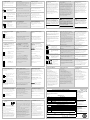
Product group
3200
Table listing restricted substances
Chinese
产品
3200
铅
汞
镉
六价铬
多溴联苯
多溴二苯醚
印刷线路板组件
XOX O O O
附属物
OOO O O O
显示器
OOO O O O
O
X
English
Product
3200
Pb
Hg
Cd
Cr(VI)
PBB
PBDE
PCBA X O X O O O
Enclosure O O O O O O
Display O O O O O O
O
X
Approval
Name: Position: Signature: Date:
Martin Greenhalgh Quality Manager
IA029470U600 (CN23172) Issue 1 Feb 07
Indicates that this toxic or hazardous substance contained in at least one of the homogeneous
materials used for this part is above the limit requirement in SJ/T11363-2006.
表示该有毒有害物质至少在该部件的某一均质材料中的含量超出
SJ/T11363-2006
标准规定的限量要求。
Toxic and hazardous substances and elements
Indicates that this toxic or hazardous substance contained in all of the homogeneous materials for
this part is below the limit requirement in SJ/T11363-2006.
Restricted Materials Table
Restriction of Hazardous Substances (RoHS)
限制使用材料一览表
有毒有害物质或元素
表示该有毒有害物质在该部件所有均质材料中的含量均在
SJ/T11363-2006
标准规定的限量要求以下。
Sales and Service
Eurotherm Ltd
Faraday Close
Worthing
West Sussex BN13 3PL
T (+44) 1903 268500
F (+44 01903) 265982
E
Ventes et Services
Eurotherm Automation SA
Lyon
T (+33 478) 664500
F (+33 478) 352490
Verkaufs und
Servicestellen
Eurotherm Deutschland GmbH
Limburg
T (+49 6431) 2980
F (+49 6431) 298119
Communications numériques
(En option)
Les communications numériques utilisent
le protocole Modbus. L'interface peut être
commandée au choix en EIA232 ou EIA485
(3 fils).
Note: La communication numérique n’est
pas disponible si la consigne externe est
installée.
Digitale Kommunikation
(Optional)
Die digitale Kommunikation verwendet
das Modbus Protokoll. Die Schnittstelle
können Sie als EIA232 oder EIA485 (3-
Leiter) bestellen.
Anmerkung: Bei externem Sollwert-
eingang ist keine digitale Kommunikation
mehr möglich.
• EIA232 et EIA485 (3-fils)
• Isolée 240Vac.
• EIA422 (5-fils) 3216 seulement
• Isolée 240Vac.
• EIA232 und EIA485 (3-Leiter)
• Isoliert 240V AC.
• EIA422 (5-Leiter) nur in 3216
• Isoliert 240V AC.
Digital Communications
(Optional)
• EIA232 and EIA485
(3-wire)
• Isolated 240Vac.
Common
Rx A(+)
Tx B(-)
HD
HE
HF
Rx+
Rx-
Com.
Tx+
Tx-
C
LA
HD
HE
HF
• EIA422 (5-wire)
3216 only
• Isolated 240Vac.
If EIA422 (5-wire) is fitted (3216 only),
the CT and LA digital input option is
not possible since EIA422 shares the
same terminals as the CT and LA.
Si la communication série EIA422 5 fils
(Modèle 3216 seulement) est installée,
les options d’entrées logiques LA et
transformateur de courant CT ne sont
pas possibles car la EIA422 partage les
même bornes que les options CT et LA.
Ist die serielle EIA422 (3-Leiter)
Kommunikation eingebaut, sind die
Digitaleingänge Optionen CT und
LA nicht möglich, da EIA422 die
gleichen Klemmen belegt wie CT
und LA.
g
Digital communications uses Modbus
protocol. The interface may be ordered
as EIA232 or EIA485 (3-wire).
Note: Digital communications is not
available if Remote SP is fitted.
• There are two inputs; 4-20mA and 0 -10
Volts which can be fitted in place of
digital communications
• It is not necessary to fit an external
burden resistor to the 4-20mA input
Remote Setpoint Input
(Optional)
Entrée Consigne Externe
(en option)
Externer Sollwerteingang
(Optional)
0
-
10
V
4-20 mA
Common Commun Common
• 2 types d’entrées : 4-20mA et 0 -10 Volts.
Elles peuvent être installées à la place de la
communication numérique.
• Il n’est pas nécessaire d’installer un shunt
externe pour l’entrée 4-20mA.
• Zwei Eingänge, 4-20 mA und 0-10 V,
können an Stelle der digitalen
Comms eingebaut werden
• Ein externer Widerstand für den
4-20 mA Eingang ist nicht nötig.
g
HD
HE
HF

Switch On
If the controller has not previously been
configured it will start up, showing the
‘Quick Configuration’ codes. This allows
you to configure the input type and range,
the output functions and the display
format.
When the controller is switched on again,
following configuration, it will start up
showing the HOME display.
!
Incorrect configuration can result
in damage to the process and/or personal
injury and must be carried out by a
competent person authorised to do so. It
is the responsibility of the person
commissioning the controller to ensure
the configuration is correct.
Erste Konfiguration
Haben Sie einen unkonfigurierten Regler,
zeigt dieser beim ersten Einschalten den
‘Quick Konfiguration’ Code. Mit dieser
eingebauten Funktion können Sie
Eingangsart und –bereich, die
Ausgangsfunktionen und das Anzeigeformat
konfigurieren.
Bei einem erneuten Einschalten (nach
Konfiguration) zeigt der Regler direkt die
Hauptseite.
!
Eine nicht korrekte Konfiguration
kann zu Beschädigungen des Prozesses und
zu Personenschäden führen. Es liegt in der
Verantwortung des Inbetriebnehmers, für
eine korrekte Konfiguration zu sorgen.
Mise sous tension
Si le régulateur n'a pas été préalablement
configuré, il affichera à sa mise sous tension les
codes de configuration rapide. Cet outil
intégré permet de configurer rapidement le
type et la plage de l'entrée, les fonctions de
sortie et le format de l'affichage.
Quand le régulateur est à nouveau mis sous
tension, selon la configuration, il démarrera
avec la page d’accueil sur l’afficheur.
!
ATTENTION : Une configuration
incorrecte peut endommager le procédé et/ou
blesser le personnel. Elle doit être effectuée
par les personnes habilitées. Il est de la
responsabilité de la personne mettant en route
le régulateur, de s’assurer que la configuration
est correcte.
Set 1
2. Full range 2. Pleine plage 2. Voller Bereich
C
o
C F
o
F
Celcius Fahrenheit
0
0-100 5
0-1000 G
32-212 M
32-1832
1
0-200 6
0-1200 H
32-392 N
32-2192
2
0-400 7
0-1400 J
32-752 P
32-2552
3
0-600 8
0-1600 K
32-1112 R
32-2912
4
0-800 9
0-1800 L
32-1472 T
32-3272
1 2 3 4 5
kchc0
Example
Exemple Beispiel
3. Input/Output 1 4. Output 2 5. Output 4
(1)
3. Entrée /Sortie 1 4. Sortie 2 5. Sortie 4
(1)
3. Eingang/Ausgang 1 4. Ausgang 2 5. Ausgang 4
(1)
X Unconfigured Non configuré Unkonfiguriert
H PID Heating (logic, relay, triac or 4-20mA or
motor valve open VP, VC only)
PID chauffage (logique, relais ou 4-20 mA ou commande
servomoteur d’ouverture VP, VC uniquement)
PID Heizen (Logik, Relais , 4-20 mA oder Klappe öffnen,
nur VP, VC)
C PID Cooling (logic, relay, triac or 4-20mA or
motor valve close VP, VC only)
PID refroidissement (logique, relais
ou 4-20 mA ou
commande servomoteur de fermeture VP, VC uniquement)
PID Kühlen (Logik, Relais , 4-20 mA oder Klappe öffnen,
nur VP, VC)
J ON/OFF Heating (logic, triac or relay), or PID 0-
20mA heating
ON/OFF chauffage (logique ou relais) ou PID 0-20 mA
chauffage
EIN/AUS Heizen (Logik, Triac oder Relais), oder PID 0-
20mA Heizen
K ON/OFF Cooling (logic, triac or relay), or PID
0-20mA cooling
ON/OFF refroidissement (logique ou relais) ou PID 0-20
mA refroidissement
EIN/AUS Kühlen (Logik oder Relais), oder PID 0-20 mA
Kühlen
Alarm
(2)
: energised in alarm
Alarme
(2)
: alarme excitée Alarm
(2)
: stromführend
0 High alarm Alarme haute Maximalalarm
1 Low alarm Alarme basse Minimalalarm
2 Deviation high Déviation haute Abweichung Hoch
3 Deviation low Déviation basse Abweichung Tief
4 Deviation band Bande Abweichung Band
Alarm
(2)
: de-energised in alarm
Alarme
(2)
: alarme désexcitée Alarm
(2)
: stromlos
5 High alarm Alarme haute Maximalalarm
6 Low alarm Alarme basse Minimalalarm
7 Deviation high Déviation haute Abweichung Hoch
8 Deviation low Déviation basse Abweichung Tief
9 Deviation band Bande Abweichung Band
DC Retransmission (not O/P4) Retransmission Analogique (sauf sortie 4 – OP4) DC Retransmission (nicht O/P4)
D 4-20mA Setpoint 4-20mA Consigne 4-20mA Sollwert
E 4-20mA Temperature 4-20mA Mesure 4-20mA Temperatur
F 4-20mA output 4-20mA Sortie 4-20mA Ausgang
N 0-20mA Setpoint 0-20mA Consigne 0-20mA Sollwert
Y 0-20mA Temperature 0-20mA Mesure 0-20mA Temperatur
Z 0-20mA output 0-20mA Sortie 0-20mA Ausgang
Logic input functions (Input/Output 1 only) Fonctions d'entrée logique (entrée/sortie 1 seulement) Logikeingang Funktionen (nur Eingang/Ausgang 1)
W Alarm acknowledge Acquittement alarme Alarmbestätigung
M Manual select Sélection manuelle Hand Auswahl
R Timer/program run Marche Tempo/prog Timer/Programm Start
L Keylock Verrouillage clavier Tastensperre
P Setpoint 2 select Sélection de consigne 2 Sollwert 2 Auswahl
T Timer/program Reset Réinitialisation pour Tempo/Prog Timer/Programm Reset
U Remote SP enable Validation de la consigne externe Freigabe externer SP
V Recipe 2/1 select Sélection recette 2/1 Rezept 2/1 Auswahl
A Remote UP button Equivalent à la touche Montée Externe MEHR Taste
B Remote DOWN button Equivalent à la touche Descente Externe WENIGER Taste
G Timer/Prog Run/Reset Réinitialisation/ Marche pour Temporisation/ Programme
Timer/Prog Start/Reset
I Timer/Program Hold Pause Temporisation/ Programme Timer /Programm Hold
Q Standby select Sélection Mode Standby Standby Auswahl
1. Input type 1. Type d'entrée 1. Eingangsart
Thermocouple Thermocouple Thermoelement
B, J, K, L, N, R, S, T Type B, J, K, L, N, R, S, T Type B, J, K, L, N, R, S, T Typ B, J, K, L, N, R, S, T
C Custom personnalisé Kunden
RTD RTD RTD
p Pt100 Pt100 Pt100
Linear Linéaire Linear
M 0-80mV 2 0-20mA 4 4-20mA
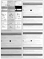
Quick Code
The quick start code
consists of two ‘SETS’ of five characters.
The upper section of the display shows
the set selected.
The lower section shows the five digits
which make up the set.
Adjust these as follows:-.
1. Press any button. The first character will
change to a flashing ‘-‘.
2. Press
W
or
V
to change the
flashing character to the required code
shown in the quick code tables –see
below. Note: An x indicates that the
option is not fitted.
3. Press
to scroll to the next
character. If you need to return to the
first character press
.
4. When all five characters have been
configured the display will go to SET 2.
When the last digit has been entered
press
again, the display will show
Press
W
or
V
to .
The controller will then automatically go
to operator level and show the HOME
display.
Der Quick Code
Der Quick Code besteht aus zwei ‘SETs’ mit
je fünf Zeichen. In der oberen Anzeige
sehen Sie den gewählten Satz. Die untere
Anzeige besteht aus den fünf Zeichen, die
das Set bezeichnen.
Stellen Sie diese wie folgt ein:
1. Drücken Sie eine Taste. Das erste
Zeichen wechselt auf ein blinkendes ‘-‘.
2. Ändern Sie mit
W
oder
V
die
blinkende Stelle, bis der gewünschte
Code erscheint (Quick Code Tabelle auf
der nächsten Seite). Anmerkung: X
bedeutet, dass die Option nicht
eingebaut ist.
3. Mit
rufen Sie die nächste Stelle auf.
Möchten Sie zur ersten Stelle zurück,
drücken Sie
.
4. Haben Sie alle fünf Stellen konfiguriert,
wechselt die Anzeige auf SET 2.
Wenn Sie das letzte Digit eingegeben
haben, drücken Sie erneut
. Die
Anzeige zeigt
Wählen Sie mit
W
oder
V
.
Der Regler geht automatisch auf die
Hauptseite in dier Bedienebene.
Le Code Rapide
Le code rapide se compose de 2 jeux (“SET”)
de 5 caractères. Le jeu sélectionné est
indiqué dans la partie supérieure de
l'afficheur, et les 5 caractères constituant le jeu
dans la partie inférieure. Les régler comme
suit :
1. Appuyer sur n'importe quelle touche. Le
premier caractère est remplacé par un
caractère clignotant ‘-‘.
2. Appuyer sur
ou
pour substituer
au caractère clignotant le code à utiliser,
indiqué dans le tableau des codes rapides -
voir section suivante. Note: un x indique
que l'option n'est pas installée.
3. Appuyer sur
pour passer au caractère
suivant. Pour revenir au premier caractère,
appuyer sur
.
4. Une fois les cinq caractères configurés,
l'afficheur passera au ‘SET 2’
Une fois le dernier chiffre saisi, appuyer de
nouveau sur
, l'afficheur indiquera
Appuyer sur
ou
jusqu'à afficher
Le régulateur passera automatiquement au
niveau opérateur et la page d’accueil/ HOME
s’affichera.
set1
*****
set2
*****
Set 2
6. Input CT Scaling Entrée TC Eingang CT Skal.
X Unconfigured Non configuré Unkonfiguriert
1 10 A 2 25 A 5 50 A 6 100 A
10. Lower Display Affichage inférieur Untere Anzeige
T Setpoint (std) Consigne (std) Sollwert (Std)
P Output Sortie Ausgang
R Time remaining Temps restant Verbleibende Zeit
E Elapsed time Temps écoulé Vergangene Zeit
1 Alarm setpoint Seuil d'alarme Alarm Sollwert
A Load Amps Courant charge Laststrom
D Dwell/Ramp
Time/Targe
Valeurs de Palier/Rampe Haltezeit/Rampe Zeit/Ziel
N None Aucun Keine
C Setpoint with Output
meter
(3)
Consigne et Sortie sur le
Vue-mètre (3)
Sollwert mit
Ausgangsmeter (3)
M Setpoint with Ammeter
(3)
Consigne et Ampèremètre (3)
Sollwert mit
Amperemeter (3)
S Prog Target setpoint Consigne cible Zielsollwert
7/8
Digital Input A/B Entrée numérique A /B Digitaleingang A/B
X Unconfigured Non configuré Unkonfiguriert
W Alarm acknowledge Acquittement alarme Alarmbestätigung
M
Manual select
Sélection manuelle
Hand Auswahl
R
Timer/Program Run
Marche
Temporisation/programme
Timer/Programm Start
L Keylock Verrouillage Clavier Tastensperre
P Setpoint 2 select Sélection consigne 2 Sollwert 2 Auswahl
T
Timer/Program reset
Réinitialisation pour
Temporisation/Programme
Timer/
Programm Reset
U
Remote SP enable
Validation de la consigne
externe
Freigabe externer SP
V Recipe 2/1 select Sélection recette 2/1 Rezept 2/1 Auswahl
A
Remote UP button
Equivalent à la touche
Montée
Externe MEHR Taste
B
Remote DOWN button
Equivalent à la touche
Descente
Ext. WENIGER Taste
G
Timer/Prog Run/Reset
Réinitialisation / Marche
Temporisation/Programme
Timer/Prog Start/Reset
I
Timer/Program Hold
Pause
Temporisation/Programme
Timer/Programm Hold
Q
Standby select (outputs
off)
Sélection Mode Standby
(Sorties Off)
Standby Auswahl
Note Input B
3208 & 04 only
Note Entrée B
3208 & 04 uniquement
Anmerkung Eingang B
Nur 3208 & 04
6
7
8
9
10
Example
Exemple Beispiel
1W R D T
9.
Output 3 (3)
Sortie 3 (3) Ausgang 3 (3)
Relay, logic, triac
outputs
Sorties relais, logique, triac Ausgänge Relais,
Logik, triac
X Unconfigured Non configuré Unkonfiguriert
H PID heating or
motor valve open
(4)
PID chauffage ou
commande servomoteur
(4)
PID Heizen oder
Klappe öffnen (4)
C
PID cooling or
motor valve close
(4)
PID refroidissement ou
commande servomoteur
(4)
PID Kühlen od.
Klappe schließen (4)
J ON/OFF heating ON/OFF chauffage EIN/AUS Heizen
K ON/OFF cooling ON/OFF refroidissement EIN/AUS Kühlen
Alarm Outputs
(5)
Sorties d'alarme
(5) Alarmausgänge (5)
Energised in
alarm
Alarme excitée Im Alarmfall
stromführend
0 High alarm Alarme haute Max Alarm
1 Low alarm Alarme basse Min Alarm
2 Dev High Déviation haute Abw. Hoch
3 Dev Low Déviation basse Abw. Tief
4 Dev Band de Bande Abw. Band
De-energised in
alarm
Alarme désexcitée Im Alarmfall
stromlos
5 High alarm Alarme haute Max Alarm
6 Low alarm Alarme basse Min Alarm
7
Dev High
Déviation haute Abw. Hoch
8 Dev Low Déviation basse Abw. Tief
9 Dev Band de Bande Abw. Band
DC outputs
Sorties DC DC Ausgänge
Retransmission Retransmission Retransmission
D 4-20 Setpoint 4-20, consigne 4-20 mA Sollwert
E
4-20 Measured
Temperature
4-20, mesure 4-20 mA
gemessene Temp.
F 4-20mA output 4-20 mA, sortie 4-20 mA Ausgang
N 0-20 Setpoint 0-20, Consigne 0-20 mA Sollwert
Y 0-20 Measured
Temperature
0-20, mesure 0-20 mA
gemessene Temp.
Z 0-20mA output 0-20mA, sortie 0-20 mA Ausgang
Control
Régulation Regelung
H 4-20mA heating 4-20 mA, chauffage 4-20 mA Heizen
C 4-20mA cooling 4-20 mA, refroidissement 4-20 mA Kühlen
J 0-20mA heating 0-20 mA, chauffage 0-20 mA Heizen
K 0-20mA cooling 0-20 mA, refroidissement 0-20 mA Kühlen
Note (1)
O/P 4 Relay only
Note (1)
Sortie 4 –relais uniquement
Anmerkung (1)
Nur Relais
Note (2)
OP1 = alarm 1; OP2 = alarm 2
OP3 = alarm 3; OP4 = alarm 4
Note (2)
OP1 = alarme 1; OP2 = alarme 2
OP3 = alarme 3; OP4 = alarme 4
Anmerkung (2)
OP1 = Alarm 1; OP2 = Alarm 2
OP3 = Alarm 3; OP4 = Alarm 4
Note (3)
3208 & 04 only
Note (3)
3208 & 04 uniquement
Anmerkung (3)
Nur 3208 & 04
Note (4)
VP, VC only
Note (4)
VP, VC uniquement
Anmerkung (4)
Nur VP, VC
To Re-Enter Quick Code
configuration mode
If you need to re-enter the ‘Quick
Configuration’ mode this can always be
done by powering down the controller,
holding down the
button, and
powering up the controller again.
You must then enter a passcode using
the
V
or
W
buttons. In a new
controller the passcode defaults to 4. If
an incorrect passcode is entered you
must repeat the whole procedure.
Erneutes Aufrufen des Quick
Code Modus
Sie können jederzeit wieder auf den Quick
Code Modus zugreifen, indem Sie den
Regler abschalten und mit gedrückter
Taste das Gerät wieder einschalten.
Halten Sie die Taste so lange gedrückt, bis
‘code’ erscheint. Geben Sie dann mit
den
V
oder
W
Tasten das Passwort
ein. In einem neuen Regler ist das
werksseitig eingestellte Passwort 4. Haben
Sie ein falsches Passwort einge-geben,
müssen Sie die gesamte Prozedur wieder-
holen. Haben Sie das Passwort richtig
eingegeben, können Sie mit Hilfe des
Quick Codes den Regler neu
konfigurieren.
Pour rappeler le mode de
configuration rapide
S'il s'avère nécessaire de revenir en mode de
configuration rapide, mettre le régulateur
hors tension, appuyer de façon continue sur
le bouton
et remettre le régulateur sous
tension en maintenant cette touche appuyée.
Le bouton doit rester enfoncé jusqu'à
affichage du message «code» . Entrer alors
le code à l'aide des boutons
ou
.
Le code par défaut d'un régulateur neuf est 4.
En cas de saisie d'un code erroné, la
procédure devra être répétée dans son
ensemble.
To Operate the
Timer/Programmer
If the timer/programmer is configured:-
To Run or Hold press
W
+
V
momentarily.
To reset press and hold
W
+
V
for
more than one second.
To Select Auto, Manual or
OFF Mode
In the HOME display:-
Press and hold
W
AND
V
(Mode)
together for more than 1 second.
Press
V
to select Manual (man), Off
(Off) and Auto (Auto).
Alarm Indication
The red ALM beacon will flash. A
scrolling text message will describe the
source of the alarm. Any output
attached to the alarm will operate.
To acknowledge the alarm:
Press
AND
(ACK) together
If the alarm is still present the ALM
beacon will light continuously.
By default alarms are configured as non-
latching, de-energised in alarm.
To adjust alarm setpoints see next panel.
Alarmanzeige
Die rote ALM Anzeige blinkt. Der
Alarmausgang (Relais) wird geschaltet und
eine durchlaufende Meldung erscheint auf
der Anzeige. Dieser Meldung können Sie
die Quelle des Alarms entnehmen
Den Alarm bestätigen
Drücken Sie gleichzeitig
und
(ACK)
Steht der Alarm weiterhin an, leuchtet die
Alarmanzeige kontinuierlich weiter.
Ab Werk sind die Alarme als nicht
gespeichert und im Alarmfall stromlos
konfiguriert.
Die Einstellung der Alarmsollwerte wird an
anderer Stelle beschrieben.
Auswahl von Auto, Hand oder
Aus
Von der Hauptanzeige:
Halten Sie
W
und
V
(Mode) für
mehr als 1 s gedrückt.
Wählen Sie mit
V
‘mAn’. Durch
erneutes Drücken erscheint ‘OFF’
Bedienung des
Programmgebers/Timers
Ist der Timer/Programmgeber konfiguriert:
Programm Starten ober Halten (Hold) kurz
W
+
V
drücken.
Programm Rücksetzen
W
+
V
drücken und für mind. 1 s halten
To Set the Target Temperature
(Setpoint)
In the HOME display:-
Press
V
to raise the setpoint
Press
W
to lower the setpoint
The new setpoint is entered when the
button is released and is indicated by a
brief flash of the display.
Einstellen des Sollwerts
Von der Hauptanzeige:
Mit
V
erhöhen Sie den Sollwert.
Mit
W
verringern Sie den Sollwert.
Der neue Sollwert wird vom Gerät
übernommen, sobald Sie die Taste
loslassen. Ein kurzes Aufblinken zeigt
Ihnen, dass der Wert jetzt aktuell ist.
Réglage de la consigne souhaitée
(consigne SP)
Depuis l'écran HOME :
Appuyer sur
pour augmenter la consigne.
Appuyer sur
pour réduire la consigne.
La nouvelle consigne est entrée une fois la
touche relâchée et confirmée par un bref
clignotement de l'affichage
Indication d'alarme
Le voyant ALM rouge clignotera, un message
déroulant indiquera la source de l'alarme et
toute sortie liée à cette alarme (par ex : relais)
sera actionnée.
Pour acquitter l'alarme
Appuyer sur
et
(Ack)
Si l'alarme est toujours présente, le voyant ALM
restera continuellement allumé.
Les alarmes sont configurées par défaut en tant
qu'alarmes non-mémorisées et désexcitées.
Pour l’ajustement des consignes d’alarme, voir le
tableau suivant.
Sélection du Mode Auto, Manuel ou
OFF
Depuis l'écran HOME :
Maintenir appuyées les touches
ET
(Mode) en même temps pendant plus de 1
seconde.
Appuyer sur
pour sélectionner “mAn”.
Appuyer à nouveau pour sélectionner OFF.
Operating Levels
There are 4 levels of operation:-
Level 1 has no password and is intended
for day to day operation.
Level 2 allows additional parameters such
as alarm setpoints and autotune to be set.
Level 3 makes all operating parameters
available. It is typically used during
commissioning - examples are range
limits, calibration offsets, units, etc.
Configuration level sets the fundamental
characteristics of the controller.
Examples are, input and output functions
and calibration.
Each level (except 1) is protected by a
security code
Level 3 and Configuration level are
described in the Engineering Manual
HA028651 available from
www.eurotherm.co.uk.
Niveaux Operatoires
Il y a 4 niveaux de fonctionnement:-
Le niveau 1 ne nécessite pas de mot de passe et
est destiné aux opérations quotidiennes.
Le niveau 2 permet de régler des paramètres
supplémentaires tels que les seuils d’alarmes et
l’auto-réglage..
Le niveau 3 met à disposition tous les paramètres
de fonctionnement. Ce niveau est typiquement
utilisé durant la mise en service - exemples :
limites d’échelle, offset d’étalonnage, unités, etc.
Le niveau de Configuration est réservé pour les
caractéristiques du régulateur. Exemples :
fonction des entrées/sorties , étalonnage.
Chaque niveau (sauf le 1) est protégé par un code
de sécurité.
Le niveau 3 et le niveau Configuration sont décrits
dans le manuel de configuration HA028651FRA
téléchargeable à partir du site
www.eurotherm.tm.fr.
Bedienebenen
Es stehen Ihnen 4 Bedienebenen zur
Verfügung:
Ebene 1 hat keinen Passwortschutz und
dient der täglichen Bedienung.
Ebene 2 bietet zusätzliche Parameter, wie
Aalrmsollwert und Selbstoptimierung.
Ebene 3 enthält alle Bedienparameter.
Dient hauptsächlich der Inbetriebnahme –
z. B. Bereichsgrenzen, Einheiten usw.
Konfigurationsebene sfür die Eingabe der
grundlegenden Reglercharakteristik. Z. B.
Funktionen von Ein- und Ausgängen,
Kalibrierung.
Die Ebenen 2, 3 und Konfig sind durch ein
Passwort geschützt.
Ebene 3 und die Konfigurationsebene
dinden Sie im Konfigurationshandbuch,
HA028651GER beschrieben
(www.eurotherm.de).
Beacons:- Voyants:- Anzeigen:
ALM Alarm active (Red) Alarme active (rouge) Alarm aktiv (Rot)
OP1
Lit when output 1 is ON (normally
heating)
Présent quand sortie 1 sur ON (chauffage)
leuchtet, wenn Ausgang 1 EIN ist (z. B.
Heizen)
OP2
Lit when output 2 is ON (normally
cooling )
Présent quand sortie 2 sur ON (refroidissement)
leuchtet, wenn Ausgang 2 EIN ist (z. B.
Kühlen)
OP3 Lit when output 3 is ON Présente quand sortie 3 sur ON leuchtet, wenn Ausgang 3 EIN ist
OP4
Lit when output 4 is ON (normally
alarm)
Présente quand relais AA sur ON (généralement
alarme)
leuchtet, wenn das AA Relais EIN ist (z. B.
Alarm)
SPX Alternative setpoint in use (SP2) Autre Consigne en utilisation (SP2) Alternativer Sollwert (SP2)
REM
Remote setpoint or
communications active
Consigne externe ou communications actives Externer Sollwert oder Kommunikation aktiv
RUN Timer/programmer running Temporisation en marche (clignotant) Timer/Programmgeber läuft
RUN
(flashing) Timer/programmer in
hold
Temporisation/Programmateur en pause (blinkt) Timer/Programmgeber angehalten
MAN Manual mode selected Mode manuel sélectionné Handbetrieb
Units (if configured) Unités (si configuré) Einheiten (wenn konfiguriert)
Measured Temperature Température mesurée Gemessene Temperatur
Target Temperature (Setpoint) or
other messages
Température cible (consigne) ou d’autres
messages
Ziel Temperatur (Sollwert ) oder andere
Nachrichten
Meter (3208 and 3204 only) Vue-mètre indicateur (3208 et 3204 seulement) Meter (nur 3208 und 3204)
Configurable as:
- Off
- Heat or cool output
- Output (Centre zero)
- Load Amps from CT
- Error signal
configurable en :
- Off (Dévalidé)
- Sortie chauffage ou sortie refroidissement
- Sortie de l'algorithme PID (Centrée sur zéro)
- Courant dans la charge fourni par le CT
- Ecart de régulation
konfigurierbar für:
- Aus
- Heiz- oder Kühlausgang
- Ausgang (Mitte = Null)
- Laststrom von CT
- Fehlersignal
Operator Buttons Touches opérateur Bedientasten
From any display - press to return
to the HOME display.
Permet de revenir sur l'écran HOME à partir de
n'importe quel écran
Mit dieser Taste kommen Sie aus jeder
Ansicht zurück in die Hauptanzeige.
Press to select a new parameter.
Hold down to continuously scroll
through parameters.
Appuyer pour sélectionner un nouveau
paramètre. Maintenir ce bouton enfoncé pour
faire défiler les paramètres.
Diese Taste dient der Auswahl eines
Parameters. Halten Sie die Taste gedrückt,
laufen die Parameter durch.
W
Press to decrease a value. Appuyer pour modifier ou réduire une valeur. Taste zum Ändern/Erhöhen eines Werts.
V
Press to increase a value. Appuyer pour modifier ou augmenter une valeur.
Taste zum Ändern/Verringern eines Werts.
HOME Display (example)
PAGE DE REPOS (
exemple
)
HAUPTANZEIGE (beispiel)
3216
g
3208
32h8
3204
Fonctionnement du
programmateur/ temporisation
Si la temporisation/programmeur est
configurée:-
Pour mettre en marche ou en pause, appuyer et
relâcher rapidement
+
Pour réinitialiser la temporisation, appuyer
pendant plus d'une seconde sur
+
.
-
 1
1
-
 2
2
-
 3
3
-
 4
4


Eurotherm 3200 Le manuel du propriétaire
- Taper
- Le manuel du propriétaire
dans d''autres langues
- English: Eurotherm 3200 Owner's manual
- Deutsch: Eurotherm 3200 Bedienungsanleitung
Documents connexes
-
Eurotherm 3216L Guide d'installation
-
-
-
-
-
-
-
-
-
Autres documents
-
Bartscher 610836 Information produit
-
Ascon tecnologic Q3 Le manuel du propriétaire
-
-
-
Stelpro RE153-RE153T-RE156 Guide d'installation
-
Mark PinTherm Connect Technical Manual
-
red lion DA PID Module Manuel utilisateur
-
 Aube Technologies 50-1133 Manuel utilisateur
-
-
BriskHeat SDCE Manuel utilisateur
