
www.metabo.com Made in Germany
de Originalbetriebsanleitung 5
en Original instructions 11
fr Notice d'utilisation originale 16
nl Oorspronkelijke gebruiksaanwijzing 22
it Istruzioni per l’uso originali 28
es Manual original 34
pt Manual original 40
sv Bruksanvisning i original 46
fi Alkuperäinen käyttöopas 51
no Originalbruksanvisning 56
da Original brugsanvisning 61
pl Instrukcja oryginalna 66
el ΕλληνικάΠρωτότυπες οδηγίες
λειτουργίας 72
hu Eredeti használati utasítás 78
ru Оригинальное руководство по
эксплуатации 84
uk Оригінальна інструкція з експлуатації 91
MAG 32
MAG 50

2
1
1
2
2
3
3
6
5
4
798
18
20
1510 11 12 13 14
16
17
22
21
19
23
24
25
26
27
MAG 50
MAG 32
23
25
26
18
21
20
19
24
654 7 8 9 16 17

3
MAG 32 MAG 50
T - Weldon, 19 mm MK2
M Nm(inlbs) 50 (443) 90 (797)
Dmax, K mm (in) 32 (1 1/4) 50 (2) / 26 (1 1/32)
Dmax, S mm (in) 13 (1/2) 20 (25/32)
Dmax, G -- M 16
P1W1000 1200
P2W520 620
n0/min 700 100-250 / 200-450
n1/min 450 250 / 450
Hmax mm (in) 160 (6 5/16) 160 (6 5/16)
Humm (in) 333 (13 1/8)457 (18)
Homm (in) 476 (18 3/4)610 (24)
A mm (in) 80 (3 5/32) x 190 (7 1/2) 90 (3 9/16) x 190 (7 1/2)
m kg (lbs) 11,9 (26.2) 12,7 (28.0)
LpA/KpA dB(A) 85 / 3 79 / 3
LWA/KWA dB(A) 98 / 3 92 / 3
13. *1) Serial Number: 00635.. *1) Serial Number: 00636..
*2) 2014/30/EU, 2006/42/EC, 2011/65/EU
*3) EN 61029-1:2009+A11:2010, EN ISO 12100:2010, EN 50581:2012
2017-04-20, Bernd Fleischmann
Direktor Produktentstehung & Qualität (Vice President Product Engineering & Quality)
*4) Metabowerke GmbH - Metabo-Allee 1 - 72622 Nuertingen, Germany

4
Ø
T
G
K
M
F
6.35115 6.35036
6.26604
MAG 50
I
6.26606
J
341148140
etc
MAG 32
MK 2 B 16
MK 2
Fein Quick In
DE
6.35304
6.26611
6.26600
L
A
H
6.26602
MK 2
A
HSS (T=55 mm); HM: 6.26609
HSS (T=30 mm): 6.26608
C
B
1/2“x20 UNF
M
etc
Fein Quick In
6.26600
HSS HM
T
Ø
Nr.
30 mm 12 mm 6.26500
30 mm 13 mm 6.26501
30 mm 14 mm 6.26502
30 mm 15 mm 6.26503
30 mm 16 mm 6.26504
30 mm 17 mm 6.26505
30 mm 18 mm 6.26506
30 mm 19 mm 6.26507
30 mm 20 mm 6.26508
30 mm 21 mm 6.26509
30 mm 22 mm 6.26510
30 mm 23 mm 6.26511
30 mm 24 mm 6.26512
30 mm 25 mm 6.26513
30 mm 26 mm 6.26514
30 mm 27 mm 6.26515
30 mm 28 mm 6.26516
30 mm 29 mm 6.26517
30 mm 30 mm 6.26518
30 mm 31 mm 6.26519
30 mm 32 mm 6.26520
T
Ø
Nr.
55 mm 12 mm 6.26521
55 mm 13 mm 6.26522
55 mm 14 mm 6.26523
55 mm 15 mm 6.26524
55 mm 16 mm 6.26525
55 mm 17 mm 6.26526
55 mm 18 mm 6.26527
55 mm 19 mm 6.26528
55 mm 20 mm 6.26529
55 mm 21 mm 6.26530
55 mm 22 mm 6.26531
55 mm 23 mm 6.26532
55 mm 24 mm 6.26533
55 mm 25 mm 6.26534
55 mm 26 mm 6.26535
55 mm 27 mm 6.26536
55 mm 28 mm 6.26537
55 mm 29 mm 6.26538
55 mm 30 mm 6.26539
55 mm 31 mm 6.26540
55 mm 32 mm 6.26541
T
Ø
Nr.
55 mm 14 mm 6.26571
55 mm 15 mm 6.26572
55 mm 16 mm 6.26573
55 mm 17 mm 6.26574
55 mm 18 mm 6.26575
55 mm 19 mm 6.26576
55 mm 20 mm 6.26577
55 mm 21 mm 6.26578
55 mm 22 mm 6.26579
55 mm 23 mm 6.26580
55 mm 24 mm 6.26581
55 mm 25 mm 6.26582
55 mm 26 mm 6.26583
55 mm 27 mm 6.26584
55 mm 28 mm 6.26585
T
Ø
Nr.
55 mm 29 mm 6.26586
55 mm 30 mm 6.26587
55 mm 31 mm 6.26588
55 mm 32 mm 6.26589
55 mm 33 mm 6.26590
55 mm 34 mm 6.26591
55 mm 35 mm 6.26592
55 mm 36 mm 6.26593
55 mm 37 mm 6.26594
55 mm 38 mm 6.26595
55 mm 39 mm 6.26596
55 mm 40 mm 6.26597
55 mm 45 mm 6.26598
55 mm 50 mm 6.26599

DEUTSCH de
5
Originalbetriebsanleitung
Wir erklären in alleiniger Verantwortlichkeit: Diese
Magnetkernbohrmaschinen, identifiziert durch
Type und Seriennummer *1), entsprechen allen
einschlägigen Bestimmungen der Richtlinien *2)
und Normen *3). Technische Unterlagen bei *4) -
siehe Seite 3.
Die MAG 32 und MAG 50 sind geeignet zum
Kernbohren mit geeigneten Schneidwerkzeugen
und zum Bohren mit Spiralbohrern in Metall.
MAG 50 ist zusätzlich geeignet zum
Gewindebohren.
Der Magnet-Bohrständer ist bestimmt zum
Befestigen an ebenem, magnetisierbarem Metall,
er muss dabei einwandfrei haften. Bei Verwendung
des mitgelieferten Sicherungsgurts zum Arbeiten
an schrägen und senkrechten Flächen und über
Kopf geeignet.
Für Schäden durch nicht bestimmungsgemäßen
Gebrauch haftet allein der Benutzer.
Allgemein anerkannte Unfallverhütungsvorschriften
und beigelegte Sicherheitshinweise müssen
beachtet werden.
WARNUNG – Zur Verringerung eines
Verletzungsrisikos Betriebsanleitung lesen.
WARNUNG Lesen Sie alle Sicherheits-
hinweise und Anweisungen. Versäumnisse
bei der Einhaltung der Sicherheitshinweise und
Anweisungen können elektrischen Schlag, Brand
und/oder schwere Verletzungen verursachen.
Bewahren Sie alle Sicherheitshinweise und
Anweisungen für die Zukunft auf.
Lesen Sie vor der Benutzung des Elektrowerkzeugs
die beiliegenden Sicherheitshinweise und die
Gebrauchsanleitung aufmerksam und vollständig
durch. Bewahren Sie alle beiliegenden Dokumente
auf und geben Sie Ihr Elektrowerkzeug nur
zusammen mit diesen Dokumenten weiter.
Beachten Sie die mit diesem Symbol
gekennzeichneten Textstellen zu Ihrem
eigenen Schutz und zum Schutz Ihres
Elektrowerkzeugs!
Zum Arbeiten an schrägen und senkrechten
Flächen und über Kopf muss der Magnet-
Bohrständer mit dem mitgelieferten
Sicherungsgurt
so gesichert werden, dass er bei
einer Unterbrechung der Stromversorgung nicht
herunterfallen kann.
Beim Ausschalten des Magneten oder im Falle
einer Unterbrechung der Stromversorgung erlischt
die Haltekraft des Magneten. Die Maschine führt
einen gefährlichen Pendelschlag aus.
Bei Überkopfarbeiten immer einen Schutzhelm
tragen.
Beim Arbeiten immer Schutzbrille,
Schutzhandschuhe und geeignetes Schuhwerk
tragen.
Achten Sie auf Beschädigungen der
Netzanschlussleitung, Schalter und Knickschutz.
Nicht an dem Werkstück, an dem die Maschine
benutzt wird, elektroschweißen.
Sollte sich etwas an der gewohnten Bedienung
ändern (z.B. Motor startet beim Einschalten des
Magneten (Schalter
(19)
): die Maschine nicht
verwenden sondern reparieren lassen. Es können
weitere Defekte auftreten.
Durch den Magneten entstehen magnetische und
elektromagnetische Felder, die sich negativ auf
medizinische Implantate auswirken können.
Die Fläche für den Elektromagneten muss sauber
und eben sein.
Die Magnethaltekraft ist abhängig von
Materialstärke und Beschaffenheit.
Farb-, Zink- und Zunderschichten reduzieren die
Magnethaltekraft.
Die Maschine nicht dem Regen aussetzen und
nicht in nassen oder explosionsgefährdeten
Räumen verwenden.
Bevor irgendeine Einstellung oder Wartung an der
Maschine vorgenommen wird, den Netzstecker aus
der Steckdose ziehen. Achtung! Beim Ausstecken
des Netzsteckers erlischt die Haltekraft des
Magneten!
Wenn der Magnet-Bohrständer (nach dem
Gebrauch) längere Zeit auf einem Material mit
ungenügender Wärmeableitung (z.B. Kunststoff)
abgestellt wird, darf man den Magneten nicht
einschalten, da dies eine Überhitzung der
Magnetspulen zur Folge haben könnte.
Befolgen Sie die Hinweise zur Schmierung und zum
Werkzeugwechsel.
Halten Sie Handgriffe trocken, sauber und frei von
Öl und Fett.
ACHTUNG! Der Gebrauch anderer
Einsatzwerkzeuge und anderen Zubehörs kann
eine Verletzungsgefahr für Sie bedeuten.
Zum Transportieren den Magnet-Bohrständer am
Tragegriff (4) halten.
Legen Sie einen Auffanggurt beim Arbeiten
auf Gerüsten an.
Gehörschutz tragen.
1. Konformitätserklärung
2. Bestimmungsgemäße
Verwendung
3. Allgemeine
Sicherheitshinweise
4. Spezielle Sicherheitshinweise

DEUTSCHde
6
Tragen Sie Augenschutz.
Warnung vor gefährlicher elektrischer
Spannung.
Warnung vor magnetischem Feld.
Verboten für Personen mit
Herzschrittmacher.
Siehe Seite 2.
1 Sicherungsgurt
2 Ratsche des Sicherungsgurts
3 zwei Haltepunkte
4 Tragegriff
5 M8-Gewinde (hier kann eine Ringschraube
eingedreht werden. Dient zum Heben der
Maschine mittels Karabiner und Seil)
6 Behälter der Kühlschmiereinrichtung
7 Zuflusshahn der Kühlschmiereinrichtung
8 Sperre gegen unbeabsichtigtes Auf-/
Abbewegen der Antriebsmaschine
9 Gewindestifte zum Einstellen des Spiels des
Schlittens
10 Schlitz im Maschinenhals zum Austreiben von
Einsatzwerkzeugen *
11 Austreiber *
12 Bohrspindel mit Werkzeugaufnahme (MK 2) *
13 Stellrad (Drehzahleinstellung) *
14 Elektronik-Signal-Anzeige *
15 Schaltknopf (1. / 2. Gang) *
16 Schlitten
17 Hebel zum Auf- und Abbewegen der
Antriebsmaschine
18 Schalter (LED-Leuchte Ein/Aus)
19 Schalter (Magnet ein-/ausschalten)
20 Schalter (Antriebsmaschine einschalten,
Rechtslauf, Bohren)
21 Schalter (Antriebsmaschine ausschalten)
22 Schalter (Antriebsmaschine einschalten,
Linkslauf) *
23 Magnetfuß / Magnet
24 Spanschutzblech
25 Gewindestifte des Werkzeughalters *
26 Werkzeughalter (Weldon, 19 mm) *
27 Verdrehsicherung *
* austattungsabhängig / typabhängig
Vergleichen Sie vor Inbetriebnahme, ob die
auf dem Typenschild angegebene
Netzspannung und Netzfrequenz mit den Daten
Ihres Stromnetzes übereinstimmen.
Überprüfen Sie die Maschine auf eventuelle
Beschädigungen: Vor weiterem Gebrauch der
Maschine müssen Schutzvorrichtungen oder leicht
beschädigte Teile sorgfältig auf ihre einwandfreie
und bestimmungsgemäße Funktion untersucht
werden. Überprüfen Sie, ob die beweglichen Teile
einwandfrei funktionieren und nicht klemmen, oder
ob Teile beschädigt sind. Sämtliche Teile müssen
richtig montiert sein und alle Bedingungen erfüllen,
um den einwandfreien Betrieb der Maschine zu
gewährleisten. Beschädigte Schutzvorrichtungen
und Teile müssen bestimmungsgemäß durch eine
anerkannte Fachwerkstatt repariert oder
ausgewechselt werden.
6.1 Netzanschluss
Die Maschine entspricht der Schutzklasse I und
darf deshalb nur an vorschriftsmäßig geerdete
Steckdosen angeschlossen werden.
Bei Verwendung der Maschine im Freien: FI-
Schutzschalter mit max. Auslösestrom (30 mA)
vorschalten!
Kontrollieren Sie regelmäßig die Anschlussleitung
des Elektrowerkzeugs und lassen Sie diese bei
Beschädigung von einem anerkannten Fachmann
erneuern.
Wenn ein Verlängerungskabel benötigt wird, muss
es dreiadrig (und sein Schutzleiter einwandfrei
leitend mit dem Schutzkontakt der Kupplungsdose
und dem des Steckers verbunden) sein.
Benutzen Sie im Freien nur dafür zugelassene und
entsprechend gekennzeichnete Verlängerungs-
kabel.
Kontrollieren Sie Verlängerungskabel regelmäßig
und ersetzen Sie diese, wenn sie beschädigt sind.
Verlängerungskabel müssen für die Leistungs-
aufnahme von Antriebsmaschine und Magnet-
Bohrständer geeignet sein (vgl. technische Daten).
Bei Verwendung einer Kabelrolle, das Kabel immer
vollständig abrollen.
7.1 Sicherungsgurt anbringen
Zum Bohren an schrägen und senkrechten
Flächen und über Kopf muss der Magnet-
Bohrständer mit dem mitgelieferten
Sicherungsgurt
(1) so gesichert werden, dass er bei einem
eventuellen Spannungsausfall nicht herunterfallen
kann.
Bringen Sie den
Sicherungsgurt
(1) so an, dass
sich der Magnet-Bohrständer bei einem
Ausbleiben der Netzspannung vom Bedienenden
weg bewegt.
Den
Sicherungsgurt
(1) austauschen wenn er
einmal durch Abfangen eines herabfallenden
Magnet-Bohrständers belastet wurde.
Achtung! Überprüfen Sie den
Sicherungsgurt
(1)
auf Beschädigungen. Überprüfen Sie vor
jedem Gebrauch den
Sicherungsgurt
(1) sorgfältig
auf einwandfreie und bestimmungsgemäße
Funktion. Wenn der
Sicherungsgurt
(1)
beschädigt
oder die Funktion der Ratsche (2) nicht mehr
einwandfrei ist, den
Sicherungsgurt
sofort
austauschen.
5. Überblick
6. Inbetriebnahme
7. Benutzung

DEUTSCH de
7
- Den
Sicherungsgurt
(1) an einem der zwei
Haltepunkte (3) des Magnet-Bohrständers
anbringen.
- Dann den
Sicherungsgurt
an einem weiteren
geeigneten Befestigungspunkt oder an dem zu
bearbeitenden Material befestigen.
- Hinweise zum
Sicherungsgurt
(1):
Stecken Sie das freie Ende des
Sicherungsgurts
(1) von unten durch den Spalt in der
Ratschenwelle und ziehen sie dann am freien
Ende des
Sicherungsgurts, bis er locker anliegt.
Er darf nicht fest anliegen, damit der
Sicherungsgurt mehr als 1 Umdrehung
aufgerollt werden kann - Nur so ist eine sichere
Befestigung möglich. Spannen sie den
Sicherungsgurt durch pumpende Bewegungen des
Ratschenhebels (a).
Lösen des
Sicherungsgurts:
Achtung, die Spannung löst sich schlagartig!
Zum Lösen des
Sicherungsgurts
klappen Sie
die Ratsche ganz auf und ziehen gleichzeitig mit
dem Finger die Verriegelungslasche (b) nach
oben.
- Achten Sie darauf, dass der Sicherungsgurt straff
geführt wird.
- Prüfen Sie die Gurtverbindung auf festen Sitz.
Der
Sicherungsgurt
ersetzt nicht die
Magnetkraft des Magnet-Bohrständers, er
dient lediglich zur Sicherung gegen Herabfallen bei
Spannungsausfall.
7.2 Kühlschmiereinrichtung für
Kernbohrarbeiten
Die Werkzeugstandzeit ist abhängig von der
Schmierung. Die Innenschmierung mit
Hochleistungsschneidöl ist bei Kernbohrarbeiten
unbedingt notwendig.
Zum Befüllen den Behälter (6) vom Magnet-
Bohrständer abnehmen.
Hochleistungsschneidöl in den Behälter (6)
einfüllen und Schraubverschluss verschließen. Am
Zuflusshahn (7) die Schmierung ein- / ausschalten.
Bei Arbeiten an senkrechten und überhängenden
Flächen und über Kopf muss der B
ehälter
(6)
entleert oder abgenommen werden, damit keine
Flüssigkeit austritt (Sonst besteht die Gefahr, dass
Hochleistungsschneidöl in den Motor gelangt und
einen Kurzschluss verursacht)
.
Bei solchen
Arbeiten das Schneidwerkzeug vor dem Bohren
von innen mit Universal-Schneid-Spray (siehe
Kapitel 10. Zubehör) einsprühen. Bei größeren
Bohrtiefen diesen Vorgang mehrfach wiederholen.
7.3 Gang und Drehzahl einstellen
(nur bei MAG 50)
Zweiganggetriebe:
Schaltknopf (15) nur bei Stillstand des Motors
betätigen.
Den gewünschten Gang durch Verdrehen des
Schaltknopfes (15) wählen. Evtl. durch leichtes
Verdrehen der Bohrspindel den Schaltvorgang
unterstützen.
Empfohlene Einstellung:
• • = 2. Gang, hohe Drehzahl: Bohren in Stahl mit
Bohrerdurchmesser bis ca. 26 mm
•= 1. Gang, hohes Drehmoment: Bohren in Stahl
mit Bohrerdurchmesser größer als ca. 26 mm
Drehzahl einstellen
Die Motor-Drehzahl lässt sich am Stellrad (13)
stufenlos verändern und so dem Material und den
Arbeitsbedingungen anpassen.
7.4 Einschalten / Einschaltreihenfolge,
Drehrichtung
Die Antriebsmaschine kann aus
Sicherheitsgründen erst nach Einschalten des
Magnets eingeschaltet werden. Daher die
Einschaltreihenfolge beachten.
1. Zuerst den Magnet einschalten: Schalter (19) auf „I“
stellen. Wenn der Magnet eingeschaltet ist, dann
leuchtet die im Schalter (19) integrierte
Signallampe.
2. Erst dann die Antriebsmaschine einschalten:
Schalter (20) = Rechtslauf (zum Bohren)
Schalter (22) = Linkslauf, nur MAG 50
Siehe auch Kapitel 9.
Bemerkung: Die volle Magnethaltekraft steht bei
eingeschalteter Antriebsmaschine zur Verfügung.
7.5 Antriebsmaschine ausschalten
Schalter (21) drücken. Warten Sie bis die
Antriebsmaschine vollständig zum Stillstand
gekommen ist.
7.6
Magnet
ausschalten
Beim Ausschalten des Magneten erlischt die
Haltekraft des Magneten.
Schalter (19) auf „0“ stellen.
7.7 Aufsetzen auf das Werkstück
Der Magnet-Bohrständer haftet nur dann
einwandfrei auf dem Material, in dem gebohrt
werden soll, wenn die Oberfläche des Materials
sauber und glatt ist. Loser Rost, Schmutz und Fett
müssen vor dem Aufsetzen des Magnet-
Bohrständers entfernt, evtl. vorhandene
Schweißperlen oder Unebenheiten müssen
geglättet werden. Falls nötig, auch den Magnetfuß
(23) reinigen.
Nach dem Einschalten des Magneten kräftig am
Tragegriff (4) des Magnet-Bohrständers rütteln, um
sich davon zu überzeugen, dass er einwandfrei auf
dem Material haftet. Wenn das nicht der Fall ist, die
Materialoberfläche und die Unterseite des
1
(b)
(a)

DEUTSCHde
8
Magnetfußes überprüfen, wenn nötig reinigen und
den Magneten nochmals einschalten.
Stahl mit geringer Dicke
Die optimale Haftwirkung wird auf
kohlenstoffarmem Stahl mit mindestens 12 mm
Dicke erreicht.
Zum Bohren in Stahl mit geringerer Dicke kann man
unter dem Material (an der Stelle, an der der
Magnetfuß aufgesetzt wird) eine Stahlplatte
(Mindestabmessungen 100 x 200 x 12 mm)
anbringen.
NE-Metalle
Zum Bohren in NE-Metallen wird die Stahlplatte auf
dem Material befestigt und der Magnet-
Bohrständer dann auf die Stahlplatte gestellt.
7.8 Das Bohren
Bevor irgendeine Einstellung oder Wartung an
der Maschine vorgenommen wird, den
Netzstecker aus der Steckdose ziehen. Achtung!
Beim Ausstecken des Netzsteckers erlischt die
Haltekraft des Magneten!
Verwenden Sie keine verformten oder
beschädigten Einsatzwerkzeuge.
Kontrollieren Sie vor jeder Verwendung
Einsatzwerkzeuge wie Kernbohrer auf
Verformungen oder Beschädigungen.
Verwenden Sie kein Zubehör, das von Metabo
nicht speziell für diese Maschine vorgesehen
und empfohlen wird. Nur weil Sie das Zubehör an
Ihrer Maschine befestigen können, garantiert das
keine sichere Verwendung.
Fehlerhaftes Befestigen und Positionieren
eines Einsatzwerkzeugs kann durch
gebrochene und weggeschleuderte Teile zu
gefährlichen Situationen führen.
Bei blockiertem Einsatzwerkzeug die
Antriebsmaschine sofort ausschalten:
Schalter (21) drücken. Einsatzwerkzeug aus der
Bohrstelle entfernen.
Generelle Hinweise:
- Spanschutzblech (24) aufstecken.
- Die Stelle an der das Loch gebohrt werden soll,
ankörnen.
- Den Magnet-Bohrständer so ausrichten, dass
sich die Bohrerspitze über der Körner-Markierung
befindet. Dazu ggf. die LED-Leuchte an Schalter
(18) einschalten.
- Den Magnet des Magnet-Bohrständers
einschalten (Schalter (19) auf „I“ stellen.).
- Sperre (8) hineinschieben.
- Anschließend die Antriebsmaschine einschalten:
Schalter (20) = Rechtslauf (zum Bohren)
Schalter (22) = Linkslauf, nur MAG 50
- Ggf. Kühlschmiereinrichtung einschalten (siehe
Kapitel 7.2.
- Den Bohrvorgang mit geringer Vorschubkraft
beginnen. Wenn der Bohrer gefasst hat, kann mit
einer etwas höheren Vorschubkraft
weitergearbeitet werden. Eine zu hohe
Vorschubkraft hat einen vorzeitigen Verschleiß
des Bohrers zur Folge. Achten Sie auf einen
regelmäßigen Spanabfluss.
- Zum Entfernen der Späne einen Spänehaken
verwenden.
- Wird das ausgebohrte Metallstück nicht
automatisch aus dem Kernbohrer ausgeworfen:
entfernen sie es mit einem Werkzeug, z.B. mit
dem Spänehaken.
Wenn der Magnet-Bohrständer (nach dem
Gebrauch) längere Zeit auf einem Material mit
ungenügender Wärmeableitung (z.B. Kunststoff)
abgestellt wird, darf man den Magneten nicht
einschalten, da dies eine Überhitzung der
Magnetspulen zur Folge haben könnte.
Spezielle Hinweise für Einsatzwerkzeuge mit
Morsekegelschaft MK2 (nur bei MAG 50):
Einsetzen
des Werkzeugs
:
Um ein
unbeabsichtigtes Auf-/Abbewegen der
Antriebsmaschine zu verhindern
: Sperre (8)
herausziehen.
Ein einwandfreier Sitz der Einsatzwerkzeuge
in der Bohrspindel (12) ist nur gewährleistet,
wenn der Innenkegel der Bohrspindel und der
Kegelschaft des Einsatzwerkzeugs frei von
Schmutz und Fett sind.
Achtung! Einsatzwerkzeuge niemals mit
Gewalt in den Innenkegel der Bohrspindel
eindrücken!
Verwenden Sie nur einwandfreie und scharfe
Einsatzwerkzeuge.
Maschine ausschalten. Netzstecker aus der
Steckdose ziehen. Achtung! Beim Ausstecken
des Netzsteckers erlischt die Haltekraft des
Magneten!
Einsatzwerkzeuge mit Kegelschaft MK2 können
direkt in den Innenkegel der Bohrspindel (12)
eingesetzt werden.
Austreiben
des Einsatzwerkzeugs:
Den Austreiber (11) - mit der Abschrägung gegen
das Einsatzwerkzeug - in den Schlitz (10) des
Maschinenhalses einführen. Lässt sich der
Austreiber nicht durch die Bohrspindel stecken,
sollten Sie die Bohrspindel (12) leicht von Hand
drehen. Das Einsatzwerkzeug durch einen leichten
Schlag mit einem Hammer auf den Austreiber (11)
austreiben.
Spezielle Hinweise für Einsatzwerkzeuge mit
Weldonschaft 19 mm:
Bei MAG 50: Zuerst die Industrieaufnahme 6.26602
(siehe Kapitel 10. Zubehör) einsetzen.
Um ein
unbeabsichtigtes Auf-/Abbewegen der
Antriebsmaschine zu verhindern
: Sperre (8)
herausziehen.
Beim Einsetzen darauf achten, dass der
seitliche Stift der Industrieaufnahme in die
Verdrehsicherung (27) eingreift.
Anschließend den Schlauch der
K
ühlschmiereinrichtung auf den Stutzen der
Industrieaufnahme
6.26602 stecken.
Einsetzen
des Einsatzwerkzeugs
:
- Den (entsprechend langen) Zentrierstift in das
Einsatzwerkzeug einsetzen.
- Das Einsatzwerkzeug so in den Werkzeughalter
(26) einführen, dass sich die beiden Flächen (am

DEUTSCH de
9
zylindrischen Teil des Einsatzwerkzeugs) an den
Stellen der Gewindestifte (25) befinden.
- Das Einsatzwerkzeug - gegen den Druck der
eingebauten Feder - bis zum Anschlag nach oben
führen und die Gewindestifte (25) mit dem
Sechskantschlüssel festziehen.
Entnehmen
des Einsatzwerkzeugs
:
- Die beiden Gewindestifte (25) lösen.
Regelmäßig warten, reinigen und schmieren.
Vor jeglicher Einstellung, Wartung, Instandhaltung
oder Instandsetzung den Netzstecker aus der
Steckdose ziehen. Achtung! Beim Ausstecken des
Netzsteckers erlischt die Haltekraft des Magneten!
Zur Schmierung der Zahnstange und des Ritzels für
die Auf- und Abwärtsbewegung des Schlittens (16)
gelegentlich einige Tropfen Öl auf die Zahnstange
geben.
Die Gleitflächen des Schlittens (16) mit Allzweckfett
schmieren.
Spiel des Schlittens
Das Spiel des Schlittens ist werksseitig
eingestellt.
Der Schlitten (16) muss so eingestellt sein, dass er
(bei eingesetzter Antriebsmaschine) leicht auf- und
abwärts bewegt werden kann, in jeder Stellung
stehen bleibt und nicht durch das Gewicht der
Antriebsmaschine nach unten gezogen wird.
Bei Bedarf kann das Spiel des Schlittens (16) mit
den drei Gewindestiften (9) eingestellt werden:
Kontermuttern lösen, Gewindestifte anziehen,
Kontermuttern wieder festziehen.
Wiederanlaufschutz (um unbeabsichtigtes
Wiederanlaufen zu verhindern)
Wenn bei eingeschalteter Antriebsmaschine
a) der Magnet ausgeschaltet wird oder
b) die Stromzufuhr unterbrochen wird,
dann kommt die Antriebsmaschine zum Stillstand.
Bei Wiedereinschalten des Magneten oder
Wiederherstellung der Stromzufuhr läuft die
Antriebsmaschine - aus Sicherheitsgründen - nicht
von selbst an (Wiederanlaufschutz). Die
Antriebsmaschine wieder einschalten.
Siehe auch Kapitel 7.4.
Elektronik-Signal-Anzeige (14) bei MAG 50
Dauerleuchten - Überlast
Die Motortemperatur ist zu hoch. Maschine
entlasten. Bei weiterer Überlastung bleibt die
Maschine stehen. Maschine aus- und wieder
einschalten und im Leerlauf abkühlen.
Der Motorteil lässt sich nicht nach oben oder
unten bewegen. Sperre (8) hineinschieben.
Verwenden Sie nur original Metabo Zubehör.
Verwenden Sie nur Zubehör, das die in dieser
Betriebsanleitung angegebenen Anforderungen
und Kenndaten erfüllt.
Siehe Seite 4.
A Kernbohrer mit 19 mm Weldonschaft, HSS/HM
B Zentrierstift kurz,
HSS: für 30 mm Schnitttiefe
HM: für Kernbohrerdurchmesser 14-17 mm
C Zentrierstift lang,
HSS: für 55 mm Schnitttiefe
HM: für Kernbohrerdurchmesser 18-100 mm
D Kegeldorn für Bohrfutter mit Innenkegel
E Zahnkranzbohrfutter mit Innenkegel
F Metallbohrer
G Schnellwechselsystem MK2 auf Weldon,
19 mm
H Industrieaufnahme MK2 auf Weldon, 19 mm
I Sicherungsgurt mit Ratsche
J Universal-Schneid-Spray
K Adapter Weldon, 19 mm, auf Gewinde ½“ x 20
UNF
L Zahnkranzbohrfutter mit Gewinde ½“ x 20 UNF
M Adapter Weldon, 19 mm, auf Fein Quick In
Zubehör-Komplettprogramm siehe
www.metabo.com oder Hauptkatalog.
Lassen Sie ihr Elektrowerkzeug durch eine
Elektrofachkraft reparieren. Dieses
Elektrowerkzeug entspricht den einschlägigen
Sicherheitsbestimmungen. Reparaturen dürfen nur
von einer Elektrofachkraft ausgeführt werden,
indem Originalersatzteile verwendet werden;
anderenfalls können Unfälle für den Benutzer
entstehen.
Reparaturbedürftige Metabo Elektrowerkzeuge
können an die auf der Ersatzteilliste angegebenen
Adressen eingesandt werden.
Bitte beschreiben Sie bei der Einsendung zur
Reparatur den festgestellten Fehler.
Metaboverpackungen sind 100% recyclingfähig.
Ausgediente Elektrowerkzeuge und Zubehör
enthalten große Mengen wertvoller Roh- und
Kunststoffe, die ebenfalls einem Recyclingprozess
zugeführt werden können.
Verpackungsmaterialien müssen entsprechend
Ihrer Kennzeichnung nach kommunalen Richtlinien
entsorgt werden. Weitere Hinweise finden Sie auf
www.metabo.com im Bereich Service.
Diese Gebrauchsanleitung ist auf chlorfrei
gebleichtem Papier gedruckt.
Nur für EU-Länder: Werfen Sie
Elektrowerkzeuge nicht in den Hausmüll!
Gemäß Europäischer Richtlinie 2012/19/EU
8. Reinigung, Wartung
9. Störungsbeseitigung
10. Zubehör
11. Reparatur
12. Umweltschutz

DEUTSCHde
10
über Elektro- und Elektronik-Altgeräte und
Umsetzung in nationales Recht müssen
verbrauchte Elektrowerkzeuge getrennt gesammelt
und einer umweltgerechten Wiederverwertung
zugeführt werden.
Erläuterungen zu den Angaben auf Seite 3.
Änderungen im Sinne des technischen Fortschritts
vorbehalten.
T =Werkzeugaufnahme
M =max. Drehmoment
Dmax, K =max. Durchmesser (Kernbohrer)
Dmax, S =max. Durchmesser (Spiralbohrer)
Dmax, G =max. Durchmesser (Gewindebohrer)
P1=Nennaufnahmeleistung
P2=Abgabeleistung
n0 =Leerlaufdrehzahl
n1=Drehzahlen bei Nennlast
Hmax =max. Hub
Hu=Höhe (einschl. Motor) bei Schlitten in der
untersten Stellung
Ho=Höhe (einschl. Motor) bei Schlitten in der
obersten Stellung
A =Abmessungen des Magnetflusses
m =Gewicht ohne Netzkabel
Typische A-bewertete Schallpegel:
LpA =Schalldruckpegel
LWA =Schallleistungspegel
KpA, KWA= Unsicherheit (Schallpegel)
Beim Arbeiten kann der Geräuschpegel 80 dB(A)
überschreiten.
Gehörschutz tragen!
Messwerte ermittelt gemäß EN 61029.
Die angegebenen technischen Daten sind
toleranzbehaftet (entsprechend den jeweils
gültigen Standards).
13. Technische Daten

ENGLISH en
11
Original instructions
On our own responsibility, we hereby declare that
these magnetic core drills, identified by type and
serial number *1), meet all relevant requirements of
directives *2) and standards *3). Technical docu-
ments for *4) - see Page 3.
The MAG 32 and MAG 50 are suitable for core
drilling with suitable cutting tools and for drilling with
spiral drills in metal. MAG 50 is also suitable for
thread tapping.
The magnetic drill stand is designed for fastening to
a magnetisable, even metal surface and must there-
fore have perfect adhesion. When used with the
securing strap provided, it is suitable for working on
vertical and angled surfaces and overhead.
The user bears sole responsibility for any damage
caused by improper use.
Generally accepted accident prevention regula-
tions and the enclosed safety information must be
observed.
WARNING – Reading the operating instruc-
tions will reduce the risk of injury.
WARNING Read all safety warnings and
instructions. Failure to follow all safety warn-
ings and instructions may result in electric shock,
fire and/or serious injury.
Keep all safety instructions and information for
future reference.
Before using the power tool, carefully read through
and familiarise yourself with all the enclosed safety
information and the Operating Instructions. Keep all
enclosed documentation for future reference, and
pass on your power tool only together with this
documentation.
For your own protection and for the
protection of your power tool, pay atten-
tion to all parts of the text that are marked
with this symbol!
For work carried out on angled and vertical
surfaces and overhead, the magnetic drill
stand must be secured with the
securing strap
supplied to prevent it from falling if the power supply
is interrupted.
When the magnet is switched off, or if the power
supply is interrupted, the magnet loses it holding
power. The machine executes a dangerous
swinging movement.
Always wear a hard hat when working overhead.
Always wear protective goggles, gloves, and suit-
able shoes when working.
Ensure there is no damage to the mains connection
cables, switch and anti-kink device.
Arc welding on the workpiece on which the machine
is used is prohibited.
If a change in normal operation is detected (e.g.
motor starts when magnet (switch (19)) is switched
on: do not use the machine but have it repaired.
Further faults can occur.
The magnet produces magnetic and electromag-
netic fields that can have a negative effect on
medical implants.
The surface for the electromagnet must be clean
and flat.
The magnet holding power depends on material
thickness and condition.
Paint, zinc and oxide layers reduce the magnet
holding power.
Do not expose the machine to rain and do not use in
wet or potentially explosive rooms.
Disconnect the mains plug from the plug socket
before performing any adjustments or maintenance
on the machine. Caution! When you unplug the
mains plug, the magnet loses its holding power.
If (after use) the magnetic drill stand is placed on a
material with low heat-dissipation characteristics for
a long period (e.g. plastic), the magnet must not be
switched on because this could lead to overheating
of the magnetic coils.
Follow the instructions for lubrication and tool
replacement.
Keep the handles dry, clean and free of oil and
grease.
Caution! The use of other tools and accessories can
result in a risk of injury.
Use the
handle (4) on the magnetic drill stand when
transporting the machine.
Always wear a safety harness when working
on scaffolds.
Wear ear protectors.
Wear protective goggles.
Danger - electrical voltage.
Danger - magnetic field.
Persons with pacemakers prohibited.
1. Declaration of Conformity
2. Specified Use
3. General safety instructions
4. Special Safety Instructions

ENGLISHen
12
See page 2.
1 Securing strap
2 Ratchet on securing strap
3 Two holding points
4 Handle
5 M8 thread (a ring bolt can be screwed in here.
Used for lifting the machine with a carabiner
and rope)
6 Container for cooling lubrication unit
7 Supply cock on cooling lubrication unit
8 Lock switch to prevent the machine from
moving up/down accidentally
9 Threaded pins for adjusting backlash of the
side plate
10 Slot in machine neck for driving out tools *
11 Removal tool *
12 Drill spindle with tool attachment (MK 2) *
13 Setting wheel (speed adjustment) *
14 Electronic signal indicator *
15 Thumbwheel (1st /2nd gear) *
16 Slide plate
17 Lever for moving driving unit up and down
18 Switch (LED lamp on/off)
19 Switch (switching on/off magnet)
20 Switch (switch on driving unit, clockwise, drill)
21 Switch (switching off driving unit)
22 Switch (switch on driving unit, counter-
clockwise) *
23 Magnet block/Magnet
24 Guard plate
25 Tool holder threaded pins*
26 Tool holder (Weldon, 19 mm) *
27 Anti-twist device*
* depending on fittings/model
Before plugging in the device, check that the
rated mains voltage and mains frequency, as
specified on the rating label, match your power
supply.
Check the machine for possible damage:
Before using the machine, you must carefully
check protective devices or slightly damaged
components to ensure they are operating perfectly
and as intended. Check that moving parts are in
perfect working order and do not jam and check
whether parts are damaged. All parts must be
correctly installed and fulfil all conditions necessary
to ensure perfect operation of the grinder. Damaged
protective devices and parts must be repaired or
replaced according to specifications by an author-
ised specialist workshop.
6.1 Mains connection
The machine is in protection class I and must there-
fore only be connected to sockets earthed
according to specifications.
Connect a FI circuit-breaker with max. release
current (30 mA) upstream when using the machine
outdoors!
Regularly check the power cable on the power tool
and have it repaired by an approved expert if
damaged.
If an extension cord is needed, it must be a three-
core lead with a protective (earth) contactor that is
properly connected to both the plug and the coupler
of the cord.
When working outdoors, only use the correspond-
ingly marked extension cable approved for this
purpose.
Regularly check extension cables and replace if
damaged.
Extension cables must be suitable for the driving
unit and magnetic drill stand power ratings (see
Technical Specifications). If using a roll of cable,
always roll up the cable completely.
7.1 Attaching the Securing Strap
For drilling work carried out on angled and
vertical surfaces and overhead, the magnetic
drill must be secured with the
securing strap
(1)
supplied to prevent it from falling if the power supply
is interrupted.
Fit the
securing strap
(1) so that the magnetic
drill stand is moved away from the operator if
the mains voltage fails.
Replace the
securing strap
(1) if it has had to
catch a falling magnetic drill stand.
Caution! Check the
securing strap
(1)
for
damage. Before using the
securing strap
(1),
always check it carefully to ensure it is operating
faultlessly and as specified. If the
securing strap
(1)
is damaged or if the ratchet (2) is no longer working
properly, replace the
securing strap
immediately.
- Fit the
securing strap
(1) on one of the two holding
points (3) of the magnetic drill stand.
- Then secure the
securing strap
to another suitable
fastening point or to the material being processed.
- Notes on the
securing strap
(1):
Insert the free end of the
securing strap
(1) from
below through the opening in the ratchet shaft and
then tension the free end of the
securing strap until
it is loosely
fitted.
The strap must not be tightly fitted: you must be
able to unroll the securing strap by more than
one rotation about the ratchet shaft - This is
essential to ensure secure fastening. Tension the
securing strap with a pumping action on the ratchet
lever (a).
To loosen the
securing strap:
5. Overview
6. Initial Operation
7. Use
1
(b)
(a)

ENGLISH en
13
Caution: the tension is released in sudden
bursts! To loosen the
securing strap
, open the
ratchet fully and simultaneously use your finger to
pull the locking strap (b) upward.
- Ensure that the securing strap is guided to be taut
in position.
- Check that the strap connection is secure.
The
securing strap
does not replace the
magnetic force of the magnetic drill stand: it is
simply used to secure against falling in the event of
a voltage failure.
7.2 Cooling Lubrication Unit for Core Drilling
The tool life depends on the lubrication. Lubricating
the inside of the core drill bit with high-performance
cutting oils is essential for core drilling.
To fill with oil, remove the container (6) from
the magnetic drill stand.
Fill the container with high-performance cutting oil
(6) and close the screw cap. Switch the lubrication
on or off at the supply cock (7).
For work carried out on vertical and overhanging
surfaces or overhead surfaces, the c
ontainer
(6)
must be emptied or removed to prevent liquid from
escaping (otherwise there is a risk of
cutting oil
entering the motor and causing a short-circuit)
.
When carrying out this type of task, spray the inside
of the cutting edge tool before drilling with universal
cutting spray (see chapter 10. Accessories).
Repeat the process several times for larger drilling
depths.
7.3 Set gear and rotational speed
(MAG 50 only)
Two-speed gear box:
Do not activate the thumbwheel (15) until the
motor has completely stopped.
Select the required gear by turning the thumbwheel
(15). If necessary, you can aid the switching proce-
dure by turning the drill spindle slightly.
Recommended setting:
• • = 2nd gear, high speed: Drilling in steel with a bit
diameter of up to approx. 26 mm
•= 1st gear, high torque: Drilling in steel with a bit
diameter larger than approx. 26 mm
Setting speed
Using the setting wheel, you can adjust the motor
speed continuously (13) and thus adapt it to the
material and working conditions.
7.4 Switching on/Switch-on Sequence, direc-
tion of rotation
For safety reasons, the driving unit can only be
switched on after the magnet has been
switched on. Please observe the switch-on
sequence.
1. First switch on the magnet: set switch (19) to "I".
When the magnet is switched on, the indicator
lamp built into the switch (19) lights up.
2. Only then should the driving unit be switched on:
Switch (20) = clockwise (for drilling)
Switch (22) = counter-clockwise, MAG 50 only
See also chapter 9.
Note: The full holding power of the magnet is avail-
able when the driving unit is switched on.
7.5 Switching off the Driving Unit
Press switch (21). Wait until the driving unit has
come to a complete standstill.
7.6
Switching off
magnet
When the magnet is switched off, the magnet
loses its holding power.
Set switch (19) to "0".
7.7 Mounting on the Workpiece
To permit the magnetic drill stand to adhere prop-
erly to material that is to be drilled, the surface must
be clean and smooth. Loose rust, dirt or grease
must be removed before mounting the magnetic
drill stand; any welding beads or surface irregulari-
ties must be smoothened. Clean the magnet block
as well (23) if necessary.
After switching on the magnet, shake the handle (4)
of the magnetic drill stand firmly to ensure that it is
adhering perfectly to the material. If it is not, then
check the condition of the surface of the material
and that of the bottom of the magnet block. Clean as
necessary and try again.
Use on thin steel
The unit adheres best to low-carbon steel that is at
least 12 mm thick.
For drilling a hole into thin steel, a steel plate meas-
uring at least 100 x 200 x 12 mm can be secured
under the material at the place where the magnetic
stand is to be positioned.
Non-ferrous metals
To drill a hole in non-ferrous metal, the steel plate
should be secured on the surface of the material
and the magnetic drill stand then placed on the steel
plate.
7.8 Drilling
Disconnect the mains plug from the plug
socket before performing any adjustments or
maintenance on the machine. Caution! When you
unplug the mains plug, the magnet loses its holding
power.
Do not use deformed or damaged tools.
Before use, always check tools such as core
drills for deformities or damage.
Do not use accessories that have not been
specified or recommended by Metabo for this
machine. The ability to attach the accessory to your
machine does not guarantee safe operation.
Securing or positioning a tool incorrectly can
cause hazardous situations due to parts
breaking or being blown off.
If a tool is blocked, switch off the driving unit
immediately: Press switch (21). Remove the
tool from the borehole.
General notes:
- Attach guard plate (24).
- Centre the position at which the hole is to be
drilled.

ENGLISHen
14
- Align the magnetic drill stand so that the drill bit is
above the centre marking. To do so, switch on the
LED lamp at switch (18) if necessary.
- Switch on the magnet of the magnetic drill stand
(set switch (19) to "I".).
- Depress (8) lock switch .
- Then switch on the driving unit: switch (20) =
clockwise (for drilling)
switch (22) = counter-clockwise, MAG 50 only
- If necessary, switch on the cooling lubrication unit
(see chapter 7.2.
- Start the drilling operation with minimum feeding
force. When the drill bit has started to drill, slightly
higher feeding force can be applied. Excessive
feeding force leads to premature wear of the drill
bit. Ensure that the chip flow is regular
- Use a wire hook to remove the chips.
- If the bored piece of metal is not automatically
ejected from the core drill, remove it using a tool,
e.g. with the wire hook.
If (after use) the magnetic drill stand is placed
on a material with low heat-dissipation charac-
teristics for a long period (e.g. plastic), the magnet
must not be switched on because this could lead to
overheating of the magnetic coils.
Special notes for tools with morse taper shank
MK2 (only applies to MAG 50):
Inserting
tool
:
To prevent the driving unit from
moving up/
down accidentally
: pull out the lock switch (8).
The tool is only guaranteed to fit perfectly in
the drill spindle (12) if the female taper of the
drill spindle and the taper shank of the tool are free
of dirt and grease.
Caution! Never use excessive force to press
tools into the female taper of the drill spindle!
Always use sharp tools in perfect condition.
Switch off the machine. Pull the mains plug
from the socket. Caution! When you unplug
the mains plug, the magnet loses its holding power.
Tools with a taper shank MK2 can be used directly
in the female taper of the drill spindle (12).
Driving out
the tool:
Insert the removal tool (11) - with the sloping edge
against the tool - in the slot (10) on the machine
neck. If the removal tool cannot be inserted through
the drill spindle, you should turn the drill spindle (12)
slightly by hand. Drive out the tool by knocking
lightly on the removal tool with a hammer. (11)
Special notes on tools with Weldon shank 19
mm:
For MAG 50: First insert the industrial attachment
6.26602 (see chapter 10. Accessories).
To prevent the driving unit from
moving up/
down accidentally
: pull out the lock switch (8).
When inserting the attachment, ensure that
the side pin of the industrial attachment
engages with the anti-twist device (27).
Then connect the hose from the c
ooling lubrication
unit to the connecting piece on the industrial attach-
ment
6.26602.
Inserting the
tool
:
- Insert the centring pin (of an appropriate length)
into the tool.
- Insert the tool in the tool holder (26) so that both
surfaces (on the cylindrical part of the tool) are
located at the positions of the threaded pins (25).
- Guide the tool upwards as far as it will go (against
the pressure of the integral spring) and tighten the
threaded pins (25) using the Allen key.
Removing
the tool
:
- Release the two threaded pins (25).
Perform regular maintenance work, cleaning and
lubrication.
Remove the mains plug from the socket before
carrying out any settings, maintenance or repairs.
Caution! When you unplug the mains plug, the
magnet loses its holding power.
For lubricating the rack and pinion that moves the
slide plate (16) up and down, a few drops of oil
should be applied occasionally to the rack.
Coat the sliding surfaces of the slide plate (16) with
multi-purpose grease.
Backlash of the slide plate
The backlash of the side plate is set ex works.
The side plate (16) must be adjusted so that it can
still be moved freely up and down (when the driving
unit is installed), and so that it will remain in any
position without the weight of the driving unit pulling
it down.
If necessary, you can adjust the backlash of the
slide plate (16) using the three threaded pins (9):
release the counternuts, tighten the threaded pins
and fasten the counternuts again.
Electronic restart protection (for preventing
accidental restarting)
If, when the driving unit is switched on,
a) the magnet is switched off or
b) the power supply is interrupted,
the driving unit comes to a standstill.
If the magnet is then reactivated or the power supply
restored, the driving unit will not restart automati-
cally for safety reasons (electronic restart protec-
tion). Switch the driving unit back on.
See also chapter 7.4.
Electronic signal indicator (14) for MAG 50
Continuously lit - Overload
The motor temperature is too high. Reduce the load
on the machine. The machine will stop if the over-
loading persists. Switch off the machine, switch it
back on again and allow to cool down at idle speed.
The motor part cannot be moved up or down.
Depress (8) lock switch .
8. Cleaning, Maintenance
9. Troubleshooting

ENGLISH en
15
Use only genuine Metabo accessories.
Use only accessories that fulfil the requirements
and specifications listed in these operating instruc-
tions.
See page 4.
A Core drill with 19 mm Weldon shank, HSS/HM
B Centring pin, short,
HSS: for 30 mm cutting depth
HM: for core drill bit diameter 14-17 mm
C Centring pin, long,
HSS: for 55 mm cutting depth
HM:0 for core drill bit diameter 18-100 mm
D Morse taper for chuck with female taper
E Key-type chuck with female taper
F Metal drill bit
G Quick replacement system MK2 on Weldon,
19 mm
H Industrial holder MK2 on Weldon, 19 mm
I Securing belt with ratchet
J Universal cutting spray
K Weldon adapter, 19 mm, on thread ½“ x 20 UNF
L Geared chuck with thread ½“ x 20 UNF
M Adapter Weldon, 19 mm, on Fein Quick In
For a complete range of accessories, see
www.metabo.com or the main catalogue.
Have your power tool repaired by a qualified electri-
cian. This power tool complies with the applicable
safety regulations. Repairs must only be carried out
by qualified electricians and using original spare
parts; otherwise the user faces a risk of accidents.
Any Metabo power tool in need of repair can be sent
to one of the addresses listed in the spare parts list.
Please attach a description of the fault to the power
tool.
Metabo's packaging can be 100% recycled.
Scrap power tools and accessories contain large
amounts of valuable resources and plastics that can
be recycled.
Packaging materials must be disposed of according
to their labelling in accordance with municipal
guidelines. Further information can be found at
www.metabo.com in the “Service” section.
These instructions are printed on chlorine-free
bleached paper.
Only for EU countries: Never dispose of
power tools in your household waste! In
accordance with European Guideline 2012/
19/EU on used electronic and electric equipment
and its implementation in national legal systems,
used power tools must be collected separately and
handed in for environmentally compatible recycling.
Explanatory notes on the specifications on page 3.
Changes due to technological progress reserved.
T =Tool attachment
M =Max. torque
Dmax, K =Max. diameter (core drill bit)
Dmax, S =Max. diameter (spiral drill bit)
Dmax, T =max. diameter (tap)
P1=Nominal power input
P2=Power output
n0=No load speed
n1=Speeds at rated load
Hmax =Max. stroke
Hu=Height (incl. motor) with slide plate in
bottom position
Ho=Height (incl. motor) with slide plate in top
position
A =Dimensions of magnetic flux
m =Weight without mains cable
A-effective perceived sound levels:
LpA =Sound pressure level
LWA =Acoustic power level
KpA, KWA= Uncertainty (noise level)
During operation the noise level can exceed
80 dB(A).
Wear ear protectors!
Measured values determined in conformity with
EN 61029.
The technical specifications quoted are subject to
tolerances (in compliance with the relevant valid
standards).
10. Accessories
11. Repairs
12. Environmental Protection
13. Technical specifications

FRANÇAISfr
16
Notice d'utilisation originale
Nous déclarons sous notre seule responsabilité :
ces perceuses à embase magnétique, identifiées
par le type et le numéro de série *1), sont conformes
à toutes les prescriptions applicables des directives
*2) et normes *3). Documents techniques pour *4) -
voir page 3.
Les supports MAG 32 et MAG 50 sont appropriés
pour le trépannage avec des outils de coupe appro-
priés et pour le perçage avec des forets hélicoïdaux
dans le métal. Le support MAG 50 est additionnel-
lement approprié pour le taraudage.
Le support de perçage magnétique est conçu pour
la fixation de métal plat aimantable, et doit pour cela
offrir une attraction parfaite. En cas d'utilisation de
la sangle de sécurité fournie, il est possible de
travailler au-dessus de la tête ainsi que sur des
surfaces verticales ou obliques.
L'utilisateur est entièrement responsable de tous
dommages résultant d'une utilisation non conforme
aux prescriptions.
Il est impératif de respecter les directives de
prévention des accidents reconnues et les
consignes de sécurité ci-jointes.
AVERTISSEMENT – Lire la notice d'utilisa-
tion afin d'éviter tout risque de blessures.
AVERTISSEMENT Lire toutes les
consignes de sécurité et instructions. Le
non-respect des consignes de sécurité et des
instructions peut être à l'origine d'un choc élec-
trique, d'un incendie et/ou de blessures graves.
Conserver toutes les consignes de sécurité et
instructions.
Avant d'utiliser l'outil électrique, lire attentivement et
entièrement les instructions de sécurité ainsi que le
mode d'emploi ci-joints. Conserver les documents
ci-joints et veiller à les remettre obligatoirement
avec l'appareil à tout utilisateur concerné.
Pour des raisons de sécurité et afin de
protéger l'outil électrique, respecter les
passages de texte repérés par ce
symbole !
Pour un travail sur des surfaces verticales ou
obliques et au-dessus de la tête, le support
de perçage magnétique doit être sécurisé à
l'aide de la
sangle de sécurité
fournie, de manière à
ce qu'il ne puisse pas chuter en cas d'interruption
de l'alimentation électrique.
En cas de désactivation de l'aimant ou de coupure
de courant, l'aimant perd sa force d'adhérence.
L'outil se met alors à effectuer des oscillations
dangereuses.
Lors d'un travail au-dessus de la tête, toujours
porter un casque de protection.
Lors du travail, systématiquement porter des
lunettes et gants de protection ainsi que des chaus-
sures adéquates.
Vérifier l'état du cordon d'alimentation au secteur,
de l'interrupteur et de la protection anti-torsion.
Pas de soudage électrique sur la pièce sur laquelle
la machine est utilisée.
Si quelque chose devait se modifier concernant la
commande habituelle (p. ex. le moteur démarre lors
de l'enclenchement de l'aimant (interrupteur
(19)
)) :
ne pas utiliser la machine, mais la faire réparer.
D'autres défauts peuvent apparaître.
L'aimant peut produire des champs magnétiques et
électromagnétiques susceptibles de créer des
nuisances sur les prothèses médicales.
La surface de l'électroaimant doit être propre et
lisse.
La force d'adhérence magnétique dépend de
l'épaisseur et des propriétés du matériau.
Les couches de peinture, de zinc et d'agent inflam-
mable réduisent la force d'adhérence de l'aimant.
Ne pas exposer la machine à la pluie et ne pas
l'utiliser dans des endroits humides ou explosifs.
Débrancher la fiche secteur de la prise de courant
avant toute opération de réglage ou de mainte-
nance. Attention ! La force de maintien de l'aimant
est désactivée en débranchant la fiche secteur !
Lorsqu'après utilisation, le support de perçage
magnétique est déposé sur un matériau offrant une
dissipation insuffisante de la chaleur (matière plas-
tique par exemple), ne pas mettre l'aimant en
marche, car cela pourrait entraîner une surchauffe
de la bobine magnétique.
Observer les consignes de lubrification et de
remplacement d'accessoire.
Maintenir les poignées propres, sèches et les
nettoyer des traces d'huile et de graisse.
Attention ! L'utilisation d'autres outils et accessoires
peut entraîner un risque de blessure.
Pour transporter le support de perçage magnétique,
le maintenir par la
poignée de transport (4).
Lors d'un travail sur un échafaudage, mettre
un harnais de sécurité.
Porter un casque antibruit !
Porter des lunettes de protection.
1. Déclaration de conformité
2. Utilisation conforme aux
prescriptions
3. Consignes de sécurité
générales
4. Consignes de sécurité
particulières

FRANÇAIS fr
17
Attention : risque de choc électrique
Attention : champ magnétique.
Interdit aux personnes portant un pace-
maker.
Voir page 2.
1 Sangle de sécurité
2 Mécanisme d'encliquetage de la sangle de
sécurité
3 Deux points de retenue
4 Poignée de transport
5 Taraudage M8 (un anneau de suspension peut
être vissé ici ; sert à soulever la machine au
moyen du mousqueton et de la corde).
6 Réservoir du dispositif de lubrification
7 Robinet d'alimentation du dispositif de
lubrification
8 Verrouillage contre un abaissement et un
relèvement involontaires de la machine
d'entraînement
9 Vis sans tête pour régler le jeu du coulisseau
10 Fente dans le col de la machine, pour
l'extraction des outils rapportés *
11 Chasse-cône *
12 Broche de perçage avec porte-outil (cône
Morse 2) *
13 Molette (réglage de la vitesse de rotation) *
14 Témoin électronique *
15 Bouton de commutation (1ère / 2ème vitesse) *
16 Coulisseau
17 Levier pour l'abaissement et le relèvement de la
machine d'entraînement
18 Interrupteur (voyant à LED marche / arrêt)
19 Interrupteur (activation / désactivation de
l'aimant)
20 Interrupteur (marche machine d'entraînement,
rotation à droite, perçage)
21 Interrupteur (arrêt de la machine
d'entraînement)
22 Interrupteur (marche machine d'entraînement,
rotation à gauche) *
23 Pied magnétique / aimant
24 Tôle de protection contre les copeaux
25 Vis sans tête du porte-outil *
26 Porte-outil (Weldon, 19 mm) *
27 Sécurité antirotation *
* en fonction de l'équipement / du type
Avant la mise en service, vérifier que la
tension secteur et la fréquence secteur indi-
quées sur la plaque signalétique correspondent aux
caractéristiques de votre réseau de courant.
Vérifier que l'outil est en bon état : avant toute
utilisation, s'assurer que les dispositifs de
protection et les pièces légèrement endommagées
fonctionnent parfaitement et de manière conforme.
Vérifier que les pièces mobiles fonctionnent parfai-
tement et ne se bloquent pas, et qu'aucune pièce
n'est endommagée. Toutes les pièces doivent être
montées correctement et satisfaire à toutes les
conditions nécessaires pour garantir le parfait fonc-
tionnement de l'outil. Si des dispositifs de protection
et des pièces sont endommagés, il faut les faire
réparer ou changer de manière conforme par un
atelier spécialisé agréé.
6.1 Raccordement au secteur
La machine correspond à la classe de protection I
et, par conséquent, doit uniquement être raccordée
à des prises de courant avec terre conformes aux
prescriptions.
En cas d'utilisation de la machine en extérieur :
monter un interrupteur de protection FI indiquant un
courant de fuite max. 30 mA !
Contrôler régulièrement le cordon d'alimentation de
l'outil électrique. En cas de détérioration, le faire
remplacer par un technicien qualifié.
Si le travail nécessite l'emploi d'un cordon prolonga-
teur, en utiliser un comportant trois fils (son fil de
terre devant être bien raccordé au contact de terre
de la prise de courant et à celui de la fiche).
Pour tout travail à l'air libre, utiliser uniquement les
cordons prolongateurs prévus à cet effet et portant
les indications correspondantes.
Contrôler régulièrement les câbles prolongateurs.
En cas de détérioration, les remplacer.
Les câbles prolongateurs doivent être adaptés à la
puissance absorbée de la machine d'entraînement
et du support de perçage magnétique (cf. caracté-
ristiques techniques). Lors de l'utilisation d'un
tambour porte-câble, toujours dérouler le câble
entièrement.
7.1 Fixation de la sangle de sécurité
Pour un perçage sur des surfaces verticales
ou obliques et au-dessus de la tête, le support
de perçage magnétique doit être sécurisé à l'aide
de la
sangle de sécurité
(1) fournie, de manière à ce
qu'il ne puisse pas chuter en cas d'éventuelle
coupure de l'alimentation électrique.
Fixer la
sangle de sécurité
(1) de sorte qu'en
cas de coupure de courant le support de
perçage magnétique bascule dans la direction
opposée à l'utilisateur.
Remplacer la
sangle de sécurité
(1) si elle a été
soumise à une sollicitation après avoir amorti
la chute du support de perçage magnétique.
Attention ! Contrôler si la
sangle de sécurité
(1)
ne présente pas d'endommagements. Avant
chaque utilisation, vérifier scrupuleusement la fonc-
tion irréprochable et conforme aux prescriptions de
la
sangle de sécurité
(1). Si la
sangle de sécurité
(1)
est endommagée ou si le mécanisme d'enclique-
5. Vue d'ensemble
6. Mise en service
7. Utilisation

FRANÇAISfr
18
tage (2) ne fonctionne plus correctement,
remplacer immédiatement la
sangle de sécurité
.
- Fixer la
sangle de sécurité
(1) à l'un des deux
points de retenue (3) du support de perçage
magnétique.
- Fixer ensuite la
sangle de sécurité
à un autre point
de fixation approprié ou au matériau à usiner.
- Consignes concernant la
sangle de sécurité
(1) :
Insérer l'extrémité libre de la
sangle de sécurité
(1)
par le bas à travers la fente dans l'arbre du méca-
nisme d'encliquetage, puis tirer l'extrémité libre de
la
sangle de sécurité jusqu'à ce qu'elle soit appliquée
de façon non serrée
.
Elle ne doit pas être appliquée de façon serrée,
afin que la sangle de sécurité puisse être
enroulée de plus de 1 tour - Une fixation sûre est
seulement possible dans ce cas. Serrer la sangle
de sécurité en effectuant des mouvements de va-et-
vient avec le levier du mécanisme d'encliquetage (a).
Desserrage de la
sangle de sécurité :
Attention, le desserrage s'effectue de façon
brusque ! Pour desserrer la
sangle de sécu-
rité
, ouvrir entièrement le mécanisme d'enclique-
tage et tirer simultanément avec le doigt la patte
de verrouillage (b) vers le haut.
- Veiller au guidage tendu de la sangle de sécurité.
- Vérifier que la sangle est solidement fixée.
La
sangle de sécurité
ne remplace pas la force
magnétique du support de perçage magné-
tique, elle agit uniquement en tant que protection en
cas de chute suite à une coupure de l''alimentation
électrique.
7.2 Dispositif de lubrification pour travaux
de trépannage
La durée de vie des outils dépend de la lubrification.
La lubrification intérieure avec de l'huile de coupe
haute performance est indispensable pour les
travaux de trépannage.
Pour le remplissage, retirer le réservoir (6) du
support de perçage magnétique.
Remplir de l'huile de coupe haute performance
dans le réservoir (6) et fermer le bouchon fileté.
Activer / désactiver la lubrification par le biais du
robinet d'alimentation (7).
Lors des travaux sur des surfaces verticales ou
inclinées, ainsi qu'au-dessus de la tête, le réservoir
(6)
doit être vidé ou retiré, afin d'éviter tout écoulement
de liquide (sinon il y a le risque que de
l'huile de coupe
haute performance ne parvienne dans le moteur et
occasionne un court-circuit)
.
Lors de tels travaux,
avant le perçage vaporiser l'outil de coupe avec de
l'huile de coupe universelle à l'intérieur (voir
chapitre 10. "Accessoires"). Dans le cas de profon-
deurs de perçage importantes, répéter plusieurs
fois ce processus.
7.3 Réglage du rapport et de la vitesse de
rotation (uniquement pour MAG 50)
Réducteur à deux vitesses :
Actionner le bouton de commutation (15)
uniquement lorsque le moteur est arrêté.
Choisir la vitesse désirée en tournant le sélecteur
(15). Aider éventuellement la sélection en tournant
légèrement la broche de perçage.
Réglage recommandé :
• • = 2ème vitesse, vitesse de rotation élevée :
perçage dans l'acier avec des diamètres
jusqu'à env. 26 mm
•= 1ère vitesse, couple élevé : perçage dans
l'acier avec des diamètres supérieurs à
env. 26 mm
Réglage de la vitesse
La vitesse de rotation du moteur peut être modifiée
en continu par l'intermédiaire de la molette (13), et
être ainsi adaptée au matériau et aux conditions de
travail.
7.4 Mise en marche / ordre d'enclenchement,
sens de rotation
Pour des raisons de sécurité, la machine
d'entraînement peut seulement être mise en
marche après l'activation de l'aimant. C'est pour-
quoi, il faut suivre l'ordre des opérations de mise en
marche.
1. D'abord activer l'aimant : positionner l'interrupteur
(19) sur„I“. Lorsque l'aimant est en marche, le
voyant intégré à l'interrupteur (19) est allumé.
2. Mettre seulement ensuite en marche la machine
d'entraînement :
interrupteur (20) = rotation à droite (pour le perçage)
interrupteur (22) = rotation à gauche, uniquement
MAG 50
Voir également chapitre 9.
Remarque : la pleine force d'adhérence magné-
tique est disponible lorsque la machine d'entraîne-
ment est en marche.
7.5 Mise en marche / Ordre des opérations
de mise en marche
Appuyer sur l'interrupteur (21). Attendre l'immobili-
sation complète de la machine d'entraînement.
7.6
Désactivation
de l'aimant
L'arrêt de l'aimant désactive sa force d'adhé-
rence.
Positionner l'interrupteur (19) sur "0".
7.7 Mise en place sur la pièce à usiner
Le support de perçage magnétique n'adhère bien
au matériau à percer que si la surface du matériau
est propre et lisse. Avant de mettre en place le
support de perçage magnétique, enlever la rouille
non adhérente, les salissures et la graisse et
éliminer les perles de soudure et autres aspérités
éventuelles. Si nécessaire, nettoyer aussi le pied
magnétique (23).
Après l'activation de l'aimant, secouer vigoureuse-
ment le support de perçage magnétique par la
1
(b)
(a)

FRANÇAIS fr
19
poignée (4) pour s'assurer de sa parfaite adhérence
sur le matériau. Si ce n'est pas le cas, vérifier l'état
de la surface du matériau et du dessous du pied
magnétique, nettoyer si nécessaire et remettre
l'aimant en marche.
Acier de faible épaisseur
La force d'adhérence de l'aimant est maximale sur
les aciers à faible teneur en carbone d'une épais-
seur minimale de 12 mm.
Pour percer l'acier de faible épaisseur, il convient
de placer une plaque en acier (dimensions mini-
males 100 x 200 x 12 mm) sous le matériau (à
l'endroit où sera posé le pied magnétique).
Métaux non-ferreux
Pour percer les métaux non-ferreux, il est néces-
saire de fixer la plaque en acier sur le matériau et de
placer ensuite le support de perçage magnétique
sur la plaque.
7.8 Perçage
Débrancher la fiche secteur de la prise de
courant avant toute opération de réglage ou
de maintenance. Attention ! La force de maintien de
l'aimant est désactivée en débranchant la fiche
secteur !
Ne pas utiliser d'outils rapportés déformés ou
endommagés. Avant chaque utilisation,
contrôler si les outils rapportés tels que les forets à
trépaner ne présentent pas de déformations ou
d'endommagements.
Ne pas utiliser d'accessoires qui n'ont pas été
prévus et recommandés par Metabo spéciale-
ment pour cette machine. Le simple fait que l’acces-
soire puisse être fixé à l'outil ne garantit pas un fonc-
tionnement en toute sécurité.
Un outil rapporté mal fixé ou mal positionné
peut conduire à des situations dangereuses
par rupture ou projection de pièces.
Si un outil rapporté se bloque, arrêter immé-
diatement la machine d'entraînement :
presser l'interrupteur (21). Retirer l'outil rapporté du
trou de perçage.
Consignes générales:
- Monter la tôle de protection contre les copeaux
(24).
- Appliquer avec un pointeau une marque de
centrage à l'emplacement où le trou doit être
percé.
- Aligner le support de perçage magnétique de
manière à ce que la pointe du foret se trouve au-
dessus de la marque de centrage. A cet égard,
mettre en marche le cas échéant la lampe à LED
via l'interrupteur (18).
- Activer l'aimant du support de perçage magné-
tique (positionner le commutateur (19) sur "I").
- Engager le dispositif de verrouillage (8).
- Mettre ensuite en marche la machine d'entraîne-
ment : interrupteur (20) = rotation à droite (pour le
perçage)
interrupteur (22) = rotation à gauche, uniquement
MAG 50
- Activer le cas échéant le dispositif de lubrification
(voir chapitre 7.2.)
- Commencer le perçage avec une force d'avance
réduite. Une fois que la perceuse mord bien,
continuer à travailler en augmentant légèrement la
force. Ne pas trop forcer, car une sollicitation
excessive de la perceuse provoque son usure
prématurée. Veiller à l'évacuation régulière des
copeaux.
- Pour enlever les copeaux, utiliser un crochet à
copeaux.
- Si la chute métallique n'est pas éjectée automati-
quement du foret à trépanner : la retire à l'aide
d'un outil approprié, p. ex. un crochet à copeaux.
Lorsqu'après utilisation, le support de perçage
magnétique est déposé sur un matériau
offrant une dissipation insuffisante de la chaleur
(matière plastique par exemple), ne pas mettre
l'aimant en marche, car cela pourrait entraîner une
surchauffe de la bobine magnétique.
Consignes spéciales pour outils rapportés
avec cône Morse de taille 2 (uniquement pour
MAG 50) :
Mise en place
de l'outil
:
Pour éviter un
abaissement et un relèvement
involontaires de la machine d'entraînement
:
retirer le dispositif de verrouillage (8).
Le parfait positionnement des outils rapportés
dans la broche de perçage (12) est unique-
ment garanti si le cône intérieur de la broche de
perçage et la tige conique de l'outil rapporté sont
exempts de salissures et de graisse.
Attention ! Ne presser au aucun cas les outils
rapportés en forçant dans le cône intérieur de
la broche de perçage !
Utiliser uniquement des outils rapportés en
parfait état et affûtés.
Arrêter l'outil. Débrancher la fiche secteur de
la prise de courant. Attention ! La force de
maintien de l'aimant est désactivée en débranchant
la fiche secteur !
Les outils rapportés avec un cône Morse de 2
peuvent être montés directement dans le cône inté-
rieur de la broche de perçage (12).
Extraction
de l'outil rapporté :
Insérer le chasse-cône (11) - avec le côté biseauté
dirigé vers l'outil rapporté - dans la fente (10) se
trouvant sur le col de la machine. Si le chasse-cône
ne se laisse pas insérer à travers la broche de
perçage, tourner légèrement la broche de perçage
(12) à la main. Chasser l'outil rapporté en appli-
quant un léger coup sur le chasse-cône (11) à l'aide
d'un maillet.
Consignes spéciales pour outils rapportés
avec tige Weldon de 19 mm :
Pour MAG 50 : insérer tout d'abord le porte-outil
spécial 6.26602 (voir chapitre 10. "Accessoires").
Pour éviter un
abaissement et un relèvement
involontaires de la machine d'entraînement
:
retirer le dispositif de verrouillage (8).
Lors de l'insertion, veiller à ce que la broche
latérale du porte-outil spécial s'engage dans la
sécurité antirotation (27).

FRANÇAISfr
20
Brancher ensuite le tuyau flexible du
dispositif de
lubrification sur la tubulure du porte-outil spécial
6.26602.
Mise en place
de l'outil rapporté
:
- Insérer la broche de centrage (de longueur
correspondante) dans l'outil rapporté.
- Insérer l'outil rapporté dans le porte-outil (26) de
manière à ce que les deux surfaces (sur la partie
cylindrique de l'outil rapporté) se trouvent au
niveau des vis sans tête (25).
- Insérer l'outil rapporté - contre la pression du
ressort intégré - vers le haut jusqu'en butée et
serrer les vis sans tête (25) à l'aide de la clé hexa-
gonale.
Retrait
de l'outil rapporté
:
- Desserrer les deux vis sans tête (25).
Assurer régulièrement la maintenance, le nettoyage
et le graissage.
Avant d'effectuer des travaux de réglage, de main-
tenance, d'entretien ou de remise en état, débran-
cher la fiche secteur de la prise de courant. Atten-
tion ! La force de maintien de l'aimant est
désactivée en débranchant la fiche secteur !
Pour lubrifier la crémaillère et le pignon engendrant
le mouvement de montée et descente du coulis-
seau (16), verser de temps en temps quelques
gouttes d'huile sur la crémaillère.
Lubrifier les portées du coulisseau (16) avec de la
graisse universelle.
Jeu du coulisseau
Le jeu du coulisseau est réglé à l'usine.
Le coulisseau (16) doit être réglé de façon à ce qu'il
puisse être déplacé facilement vers le haut et vers
le bas (avec machine d'entraînement mise en
œuvre), qu'il s'immobilise dans chaque position et
qu'il ne soit pas tiré vers le bas par le poids de la
machine d'entraînement.
Si nécessaire, le jeu du coulisseau (16) peut être
réglé par le biais des trois vis sans tête (9) :
desserrer les contre-écrous, serrer les vis sans tête,
resserrer les contre-écrous.
Protection antidémarrage (pour éviter tout
redémarrage intempestif de l'outil)
Si, lorsque la machine d'entraînement est enclen-
chée,
a) l'aimant est désactivé ou
b) l'alimentation électrique est coupée,
alors la machine d'entraînement est immobilisée.
Pour des raisons de sécurité, lors de la réactivation
de l'aimant ou du rétablissement de l'alimentation
électrique, la machine d'entraînement ne redé-
marre pas automatiquement (protection antidémar-
rage). Remettre en marche la machine d'entraîne-
ment.
Voir chapitre 7.4.
Témoin électronique (14) pour MAG 50
Allumé en continu - surcharge
La température du moteur est trop élevée. Délester
la machine. La machine s'arrête si la surcharge
persiste. Arrêter la machine et la remettre en
marche, puis la laisser refroidir au ralenti.
Le moteur ne se déplace pas vers le haut ou
vers le bas. Engager le dispositif de verrouillage
(8).
Utiliser uniquement des accessoires Metabo.
Utilisez uniquement des accessoires, qui sont
conformes aux exigences et aux données caracté-
ristiques indiquées dans les présentes instructions
d'utilisation.
Voir page 4.
A Forets à trépanner avec tige Weldon de 19 mm,
acier à coupe très rapide / carbure
B Broche de centrage courte, acier à coupe très
rapide : pour profondeur de coupe 30 mm
carbure : pour diamètres de forets à trépanner
14-17 mm
C Broche de centrage longue,
acier à coupe très rapide : pour profondeur de
coupe 55 mm
carbure : pour diamètres de forets à trépanner
18-100 mm
D Mèche conique pour porte-foret avec cône inté-
rieur
E Mandrin à clé avec cône intérieur
F Foret à métal
G Système de changement rapide cône Morse 2
sur Weldon 19 mm
H Porte-outil spécial cône Morse 2 sur Weldon
19 mm
I Sangle de sécurité avec mécanisme
d'encliquetage
J Spray huile de coupe universelle
K Adaptateur Weldon, 19 mm, sur filetage ½“ x 20
UNF
L Mandrin de perçage à couronne dentée avec
filetage ½“ x 20 UNF
M Adaptateur Weldon, 19 mm, sur "Fein Quick In"
Voir programme complet des accessoires sur
www.metabo.com ou dans le catalogue principal.
Faites réparer vos outils électriques par un électri-
cien. Cet outil électrique satisfait aux prescriptions
de sécurité en vigueur. Les réparations doivent
uniquement être effectuées par un électricien, en
utilisant des pièces de rechange d'origine ; dans le
cas contraire, il peut en résulter des accidents pour
l'utilisateur.
Les outils Metabo à réparer peuvent être expédiés
à l'une des adresses indiquées sur la liste des
pièces de rechange.
Prière de joindre à l'appareil expédié une descrip-
tion du défaut constaté.
8. Nettoyage, maintenance
9. Dépannage
10. Accessoires
11. Réparation
La page est en cours de chargement...
La page est en cours de chargement...
La page est en cours de chargement...
La page est en cours de chargement...
La page est en cours de chargement...
La page est en cours de chargement...
La page est en cours de chargement...
La page est en cours de chargement...
La page est en cours de chargement...
La page est en cours de chargement...
La page est en cours de chargement...
La page est en cours de chargement...
La page est en cours de chargement...
La page est en cours de chargement...
La page est en cours de chargement...
La page est en cours de chargement...
La page est en cours de chargement...
La page est en cours de chargement...
La page est en cours de chargement...
La page est en cours de chargement...
La page est en cours de chargement...
La page est en cours de chargement...
La page est en cours de chargement...
La page est en cours de chargement...
La page est en cours de chargement...
La page est en cours de chargement...
La page est en cours de chargement...
La page est en cours de chargement...
La page est en cours de chargement...
La page est en cours de chargement...
La page est en cours de chargement...
La page est en cours de chargement...
La page est en cours de chargement...
La page est en cours de chargement...
La page est en cours de chargement...
La page est en cours de chargement...
La page est en cours de chargement...
La page est en cours de chargement...
La page est en cours de chargement...
La page est en cours de chargement...
La page est en cours de chargement...
La page est en cours de chargement...
La page est en cours de chargement...
La page est en cours de chargement...
La page est en cours de chargement...
La page est en cours de chargement...
La page est en cours de chargement...
La page est en cours de chargement...
La page est en cours de chargement...
La page est en cours de chargement...
La page est en cours de chargement...
La page est en cours de chargement...
La page est en cours de chargement...
La page est en cours de chargement...
La page est en cours de chargement...
La page est en cours de chargement...
La page est en cours de chargement...
La page est en cours de chargement...
La page est en cours de chargement...
La page est en cours de chargement...
La page est en cours de chargement...
La page est en cours de chargement...
La page est en cours de chargement...
La page est en cours de chargement...
La page est en cours de chargement...
La page est en cours de chargement...
La page est en cours de chargement...
La page est en cours de chargement...
La page est en cours de chargement...
La page est en cours de chargement...
La page est en cours de chargement...
La page est en cours de chargement...
La page est en cours de chargement...
La page est en cours de chargement...
La page est en cours de chargement...
La page est en cours de chargement...
La page est en cours de chargement...
La page est en cours de chargement...
La page est en cours de chargement...
La page est en cours de chargement...
-
 1
1
-
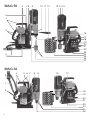 2
2
-
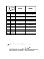 3
3
-
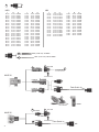 4
4
-
 5
5
-
 6
6
-
 7
7
-
 8
8
-
 9
9
-
 10
10
-
 11
11
-
 12
12
-
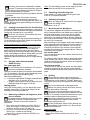 13
13
-
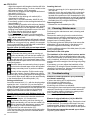 14
14
-
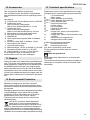 15
15
-
 16
16
-
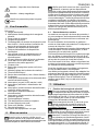 17
17
-
 18
18
-
 19
19
-
 20
20
-
 21
21
-
 22
22
-
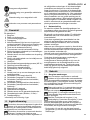 23
23
-
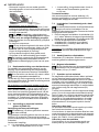 24
24
-
 25
25
-
 26
26
-
 27
27
-
 28
28
-
 29
29
-
 30
30
-
 31
31
-
 32
32
-
 33
33
-
 34
34
-
 35
35
-
 36
36
-
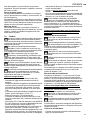 37
37
-
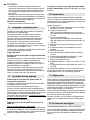 38
38
-
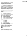 39
39
-
 40
40
-
 41
41
-
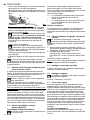 42
42
-
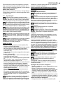 43
43
-
 44
44
-
 45
45
-
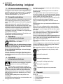 46
46
-
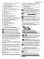 47
47
-
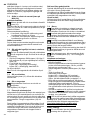 48
48
-
 49
49
-
 50
50
-
 51
51
-
 52
52
-
 53
53
-
 54
54
-
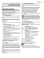 55
55
-
 56
56
-
 57
57
-
 58
58
-
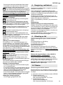 59
59
-
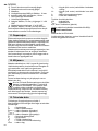 60
60
-
 61
61
-
 62
62
-
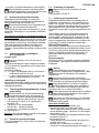 63
63
-
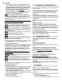 64
64
-
 65
65
-
 66
66
-
 67
67
-
 68
68
-
 69
69
-
 70
70
-
 71
71
-
 72
72
-
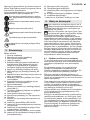 73
73
-
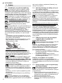 74
74
-
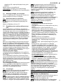 75
75
-
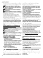 76
76
-
 77
77
-
 78
78
-
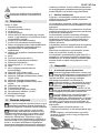 79
79
-
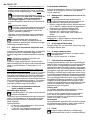 80
80
-
 81
81
-
 82
82
-
 83
83
-
 84
84
-
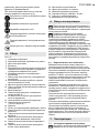 85
85
-
 86
86
-
 87
87
-
 88
88
-
 89
89
-
 90
90
-
 91
91
-
 92
92
-
 93
93
-
 94
94
-
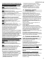 95
95
-
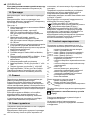 96
96
-
 97
97
-
 98
98
-
 99
99
-
 100
100


Metabo MAG 32 Mode d'emploi
- Taper
- Mode d'emploi
- Ce manuel convient également à
dans d''autres langues
- italiano: Metabo MAG 32 Istruzioni per l'uso
- português: Metabo MAG 32 Instruções de operação
- dansk: Metabo MAG 32 Betjeningsvejledning
- svenska: Metabo MAG 32 Bruksanvisningar