Senco FN81T1 Manuel utilisateur
- Catégorie
- Cloueuse
- Taper
- Manuel utilisateur

FN81T1 / FN91T1
PNEUMATIC
FRAMING NAILERS
Operating Instructions
KYOCERA-SENCO Industrial Tools, Inc.
8450 Broadwell Road
Cincinnati, OH 45244
1-800-543-4596
www.senco.com © 2021 by KYOCERA-SENCO Industrial Tools, Inc.
NFD8FN81TFN91T • Issued October 4, 2021
IMPORTANT:
Read before use.
Warnings for the safe use of this tool are included in this manual.
Los avisos para el uso seguro de esta herramienta están incluidos en este manual.
Les consignes pour l’utilisation en toute sécurité de cet outil se trouvent dans ce manuel.

Table of Contents
Employer’s Responsibilities ....................................................................................................................... 2
Safety Warnings ......................................................................................................................................... 3
Maintenance ............................................................................................................................................... 6
Functional Operation (FN81T1) .................................................................................................................. 8
Functional Operation (FN91T1) .................................................................................................................. 9
Tool Use ................................................................................................................................................... 10
Actuation System ..................................................................................................................................... 10
Clearing Jam ............................................................................................................................................ 11
Features ................................................................................................................................................... 11
Troubleshooting ....................................................................................................................................... 12
Accessories .............................................................................................................................................. 13
Options .................................................................................................................................................... 13
Technical Specifications ........................................................................................................................... 13
Fastener Specifications ............................................................................................................................ 14
Limited Warranty ..................................................................................................................................... 15
Employer’s Responsibilities
Keep this manual available for use by all people assigned to the use of this tool.
Employer must enforce compliance with the safety warnings and all other instructions which accompany
this tool as shipped from the manufacturer.
Tool actuation system must be appropriate taking into consideration the work application.
The operator must be trained in the safe use of the tool described in the operating safety manual.
Only persons who have read and understand the tool operating safety instructions shall operate the tool.
2

3
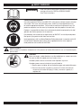
SAFETY WARNINGS
WARNING
Read and understand tool labels and manual. Failure to follow
warnings will result in DEATH or SERIOUS INJURY.
Save These Instructions.
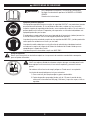
Personal Protective Equipment
Use safety equipment. Always wear ANSI Z87+ safety glasses with permanently attached
side shields. Dust mask, non-skid safety shoes, hard hat, or hearing protection must
be used for appropriate conditions. Failure to do so could result in personal injury. Eye
protection equipment must be worn by the operator and other people in the work area.
Employer is responsible to enforce the use of personal protective equipment by the tool
operator and all other personnel in the work area.
Eye protection shall conform to the requirements of ANSI Z87+ and shall provide protec-
tion against flying particles both from front and side.
Hearing protection shall have Noise Reduction Rating determined in accordance with US
Environmental Protection Agency Rules that is appropriate for the noise exposure.
Head protection shall conform to ANSI Z89.1.
Explosion Hazard
Never use tool in an explosive atmosphere or in the presence of combustible materials such as flammable liquids,
gases or dust.
Hazardous
Never use oxygen, carbon dioxide or any other bottled gas as a power source for
this tool; the tool will explode and cause serious injury.
Hazardous power sources shall not be used. Explosion may occur.
Hazardous power sources include, but are not limited to:
1. Reactive gases including, but not limited to oxygen and combustible gases.
2. Pressure sources that can deliver in excess of 1.5 times the maximum
air pressure of a tool or 200 psig (13.8 bar), whichever is greater, if a
regulator fails.

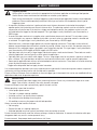
SAFETY WARNINGS
Triggering Systems
Always select an actuation system that is appropriate for the fastener application and training of tool operator.
Contact Senco at www.senco.com for information on actuation system options.
Tools are manufactured with a variety of triggering systems based on tool application, fastener size and operator
preference. Please read the operating instructions so that you are familiar with the operation of each type of
triggering system.
• A sequential actuation mechanism is preferred when exact fastener placement is desired or the employer /
operator prefer that the tool be reset for each fastener drive. The operating controls must be activated in a specific
sequence to activate the tool. If the tool has a trigger and workpiece contact, the workpiece contact must be
activated before the trigger for the tool to operate. This type trigger is easily identified in your Senco tool by a
GREY trigger.
• A contact actuation mechanism is an option when rapid fastener placement is desired. This actuation system
can be activated in any sequence. Additional activations can occur when any operating control is released and
re-activated. This type trigger is easily identified in your Senco tool by a BLACK trigger.
• Some tools have a selectable trigger option built into the triggering mechanism. These tools can be switched
between sequential operation and contact actuation by moving a button, lever or switch. See operator manual to
determine if this selectable trigger is provided in your fastener driving tool. This type trigger is easily identified in
your Senco tool by a RED trigger or BLACK trigger with RED switch.
• Light duty tools may have only a finger trigger and do not require a work contact element. These tools are used in
specialty applications and are typically used in industrial applications.
• Light duty tools may have a dual action trigger. The two - stage trigger must be actuated in a sequence in order to
drive a fastener. This type tool does not require a work contact element and is used for specialty applications.
• Some special application tools utilize a retracted workpiece contact mechanism. These tools are used for attaching
straps to plates through pre-punched holes.
*Trigger color designation does not apply to metal connector.
It is recommended that operators that are less experienced using pneumatic fastener driving tools choose a sequential
mechanism until they become familiar with the tool and its operation.
Please call Senco Customer Service to obtain an alternate trigger type in those tools that can be user modified to fit the
application and/or level of operator experience.
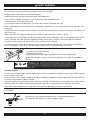
Personal Safety
Always remove finger from trigger when not driving fasteners. Never carry the tool with finger on or under
trigger. Tool will eject a fastener if the safety element is bumped.
Do not actuate tool unless tool is placed firmly against the work surface.
Before operating, inspect tool to confirm:
• Use of proper power source.
• That tool is in proper working condition.
• Actuation system is on tool and how it operates.
• No misalignment or binding of moving parts.
• All conditions necessary for proper and safe tool operation.
Always assume the tool contains fasteners.
• No horseplay.
• Respect the tool as a working implement.
• Keep tool pointed away from yourself and others when connecting air to tool.
Do not use tool while tired or under the influence of drugs, alcohol or medication. A moment of inattention while oper-
ating power tools may result in serious personal injury.
Do not overreach. Keep proper footing and balance at all times.
4

SAFETY WARNINGS
5
Always place yourself in a firmly balanced position.
Stay alert, focus on your work and use common sense when using tool.
Keep bystanders and children away while operating tool.
Store idle tools out of the reach of minors or other untrained persons.
Drive fasteners into work surface only; never into materials too hard to penetrate.
Do not force tool. Let the tool do the work.
Use the correct tool for the application. The correct tool will do the job better and safer.
Tools shall be operated at the lowest pressure needed for the application. This will reduce noise levels, part wear, and
energy use.
Do not drive fasteners on top of other fasteners or with the tool at too steep of an angle; the fasteners can ricochet and
may cause injury.
When using tool, care should be taken due to possibility of tool recoil after a fastener is driven.
If safety element is unintentionally allowed to re-contact work surface following a recoil, an unwanted fastener will be
driven. Therefore, allow tool to recoil completely off work surface after a fastener is driven to avoid this condition.
Do not push safety element on work surface until a second fastener is desired.
Do not drive fasteners close to the edge of the work surface. Keep face and body parts away from tool and work sur-
face. The workpiece is likely to split and the fastener could fly free or ricochet and may cause injury.
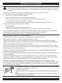
2
1
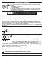
Tool may eject a fastener when connected to air supply; therefore,
① remove all fasteners from tool
② before connecting air.
Do not load fasteners with trigger or workpiece contact element depressed.
Keep hands and body away from the fastener discharge area of tool near workpiece
contact.
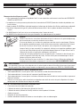
(1) Read and understand tool labels and manual. Failure to follow
warnings will result in DEATH or SERIOUS INJURY. (2) Operators and
others in work area MUST wear safety glasses with side shields. (3) Keep fingers AWAY from trigger
when not driving fasteners to avoid accidental firing. (4) See manual for triggering instructions.
(5) NEVER point tool at yourself or others in work area. (6) NEVER use oxygen or other bottled gases. Explosion may occur.
(7) MAX AIR PRESS. 120 PSI (8.3 BAR)
Operating Controls
Do not use tool without danger label on tool. If label is missing, damaged or unreadable, contact your SENCO represen-
tative to obtain a new label.
Never use tool if safety element, trigger or springs have become inoperable, missing or damaged. Do not tamper with
or remove safety element, trigger or springs.
Disconnect tool from air before doing tool maintenance, clearing a jammed fastener, leaving work area, moving tool to
another location or handing the tool to another person, when not in use or outside of the operator’s supervision.
Tools shall not be modified unless authorized in tool manual or approved in writing by manufacturer.
Use only parts, fasteners, and accessories recommended or sold by SENCO. Do not modify tool without authorization
from SENCO.
Proper Power Source
Use only clean, dry, regulated compressed air at recommended pressure.
Do not operate the tool with any alternate power source.

SAFETY WARNINGS
6
200 psig
13.7 bar
Do not connect tools to air pressure that potentially exceeds 200 psig or 13.7 bar.
Regulators shall be used to limit compressed air pressure supplied to tool.
Regulators shall be set at an operational pressure that is lower than or equal to
manufacturers specified maximum.
Air hose must have a minimum working pressure rating of 150 PSIG (10.3 bar) or
150% of the maximum pressure produced in the system, whichever is higher.
The tool and air supply hose must have a hose coupling such that all pressure is
removed from the tool when the coupling joint is disconnected.
Use extra caution when driving fasteners into existing walls or other blind areas to prevent contact with hidden objects
or persons on other side (e.g. wires, pipes, etc.).
Never use a tool that leaks air or needs repair.
Never lift, pull or lower the tool by the hose.
Keep tool pointed away from yourself and others while connecting air to the tool.
Never use any part of the tool (cap or main body) as a hammer. The tool could activate or become unsafe.
Read and understand all safety instructions.
Product Safety Messages
• Read and Understand tool labels and manual. Failure to follow warnings will result in DEATH or SERIOUS INJURY.
• Operators and others in work area MUST wear safety glasses with side shields.
• Keep fingers AWAY from trigger when not driving fasteners to avoid accidental discharge.
• Know and understand what trigger system you are using. Check manual for triggering options.
• NEVER point tool at yourself or others in work area.
• NEVER use oxygen or other bottled gases. Explosion may occur.
Maintenance
Always refer to both tool maintenance instructions below and the troubleshooting
guide in this manual to assure years of reliable service.
Make sure all screws and caps are securely tightened at all times. Make daily inspec-
tions for free movement of trigger and safety element. Never use the tool if parts are
missing or damaged.
When tool is disconnected from air, make daily inspection to assure free movement of
safety element and trigger. Do not use tool if safety element or trigger sticks or binds.
Squirt Senco pneumatic oil (5 to 10 drops) into the air inlet twice daily (depending on
frequency of tool use). Other oils may damage O-rings and other tool parts.
Wipe tool clean daily and inspect for wear. Use non-flammable cleaning solutions only
if necessary. DO NOT SOAK.
WARNING
Repairs other than those described here should be performed only by trained, qualified personnel. Contact
SENCO for information at 1-800-543-4596.

SAFETY WARNINGS
7
The employer, tool owner and tool operator:
• are responsible for ensuring that the tools are kept in safe working order.
• are responsible for ensuring that only qualified personnel shall repair the tool.
• are responsible for ensuring that manufacturers tool maintenance instructions are available to personnel
performing maintenance.
• shall ensure that tools that require repair are removed from service and that tags and physical segregation are
used as a means of control.
Tool conditions that require the tool to be taken out of service:
• Excessive leaks from pressure vessel.
• Inoperable workpiece contact (safety element).
• Workpiece contact (safety element) that appears to bind during use.
• Missing guards.
• Missing safety labels.
• Delayed firing due to worn or damaged parts.

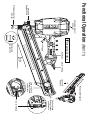
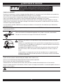
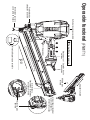
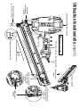
Grasping Surface
Belt Hook
Removable Magazine
Cock and Load
Fastener Feeder
and Release
Load and Cock
Fastener Feeder
and Release
Press to Release
Removable
No Mar Pad
Workpiece Contact
Element
Inlet Air Fitting Loosen to
Remove
Adjustable Exhaust
Deflector
Adjustable
Depth of Drive
Trigger
20˚
Functional Operation (FN81T1)

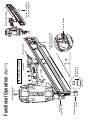
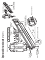
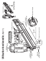
Functional Operation (FN91T1)
Grasping Surface
Belt Hook
Removable Magazine
Load and Cock Fastener
Feeder and Release
Press to Release
Removable
No Mar Pad
Workpiece Contact
Element
Inlet Air Fitting
Remove these 2 Bolts
to Remove Magazine
Adjustable Exhaust
Deflector
Adjustable
Depth of Drive
Trigger
34˚

10
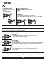
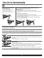
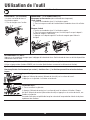
Tool Use
Read section titled “Safety Warnings” before using tool.
TO LOAD: (CLIPPED HEAD)
➀ Insert strip of nails into rear of
magazine
➁ Pull feeder shoe back.
TO LOAD: (FULL ROUND HEAD)
Dual-Mode Loading (Two methods to load)
Nails First
➀ Insert strip of nails into the rear of the magazine.
➁ Pull feeder shoe back beyond the end of the strip of nails and release.
OR
Feeder Shoe First
➀ Insert strip of nails into the rear of the magazine.
➁ Pull feeder shoe all the way back until latch at rear of magazine locks.
③ Push down on silver latch at rear of the magazine to release feeder shoe.
1
2123
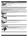
UNLOADING THE TOOL:
Push Tab on feeder shoe to release feeder from strip. Pull fastener strip out past sheet metal nail detainer.
Do not load with workpiece contact (safety element) or trigger depressed.
Use only genuine SENCO fasteners (see Fastener Specifications).
Actuation System:
With a Contact-Actuation (“Dual-Action”) trigger, fasteners can be driven two ways:
1
2
The First Way:
➀ Press the workpiece contact (safety element) against the work surface.
➁ Pull the trigger and the fastener is driven.
2
1
The Second Way:
➀ Pull and hold trigger.
➁ Depress workpiece contact element against work surface and drive a fastener. Each time you
push the workpiece contact (safety element) against the work surface, a fastener is driven.
This mode of operation is preferred when you desire high production, and rapid fastener place-
ment.
1
2
With a Sequential Actuation (Restrictive) trigger, fasteners can only be driven one way:
➀ Press the workpiece contact (safety element) against the work surface.
➁ Pull the trigger.
This mode of operation is helpful when you require precise fastener placement.
Read the “Customer Satisfaction and Safety Reminder” (CSSR) in the tool and fastener boxes for safety infor-
mation regarding the Contact-Actuation and Sequential trigger modes. Under certain conditions, the Sequential
trigger mode may reduce the possibility of injury to you or to others working with you.

11
TOOL USE
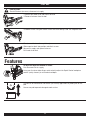
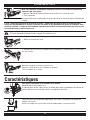
Clearing Jams:
Should a fastener jam occur, disconnect air supply.
2
1
➀ Release the feeder shoe and slide it forward.
➁ Remove fasteners from the tool.
3
③ Loosen screws using hex wrench at the rear of the tool by hand. Pull magazine back.
Clear jammed fastener from guide body.
Slide magazine back into position and attach screws.
Connect air supply and replace fasteners.
Pull feeder shoe back.
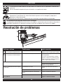
Features
To adjust the depth the fastener is driven:
First disconnect the air supply.
Using your thumb or index finger, rotate wheel to adjust the Depth Control workpiece
contact (safety element) to achieve desired depth.
The tool can be converted for non-toenail (flat surface) applications by adding the no-mar
pad.
Use no-mar pad to prevent damage to work surface.

12
FEATURES
The deflector can be rotated to 3 positions to change the direction of the exhaust air.
Disconnect air supply, loosen cap screw with a hex wrench, and then rotate deflector to
desired direction.
Prior to tool use, ensure deflector cap screw is tightened.
This tool is equipped with a lockout feature:
When approximately five nails remain in the magazine, the workpiece contact (safety element) will be locked in the
undepressed position until more nails are loaded into the magazine.
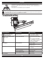
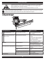
Troubleshooting
1
2
Problem/Symptom Potential Cause Corrective Action
①Air leak near top of tool /
Sluggish operation Firing valve seal Verify air supply / Tighten screws
or install Parts Kit YK0893
②Air leak near bottom of tool /
Poor return Piston stop/Piston seal Check for piston seal or sleeve
wear
If parts are worn or damaged,
parts are detailed in the parts chart
Clean tool / Tighten screws or
install Parts Kit YK0894
Tool skipping Low air pressure Check air supply
Consider using larger diameter air
fitting and hose
Nail set above work surface Low air pressure Increase air pressure (No greater
than 120 psi)
Application too rigorous Consider alternate type of wood
Rate of drive too fast Reduce drive rate
Incorrect depth of drive Adjust setting
Other problems Contact SENCO

13
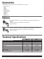
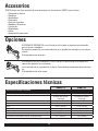
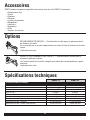
Accessories
SENCO offers a full line of accessories for your SENCO tools, including:
• Air Compressors
• Hose
• Couplers
• Fittings
• Safety Glasses
• Pressure Gauges
• Lubricants
• Regulators
• Filters
• No Mar Pads
Options
SEQUENTIAL TRIGGER—This feature is helpful when precise fastener placement is
required.
Identified by extra spring at hinge pin and internal lever.
Trigger will be grey.
CONTACT ACTUATION TRIGGER—This feature is used for rapid fastener placement.
Read the safety warning on page 4 for additional recommendations.
Trigger will be black.
Technical Specifications
FN81T1 FN91T1
Technical SpecificaTionS
Minimum to maximum operating pressure 70 - 120 psig 70 - 120 psig
Air Consumption 0.112 scfm/drive 0.111 scfm/drive
Air Inlet 3/8" NPT 3/8" NPT
Nail Angle 20 Degree 34 Degree
Weight 8.8 lbs. (4.0 kg) 8.5 lbs. (3.8 kg)
Fastener Capacity 63 80
Tool size: Height 14.6" (371mm) 14.4" (366mm)
Tool size: Length 20.7" (526mm) 17.3" (439mm)
Tool size: Width: Main Body 4.8" (122mm) 4.8" (122mm)

14
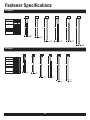
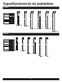
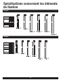
Fastener Specifications
34 Degree
HCGCGE KC
A A A A
.113"
2,9 mm .113"
2,9 mm
.120"
3,1 mm
.131"
3,3 mm
HE
A
.120"
3,1 mm
HF
A
.120"
3,1 mm
â Rounded to nearest 5mm
mm
50
60
50
57
60
65
75
75
75
75
83
90
A
inches
2
2-3/8
2
2-1/4
2-3/8
2-1/2
3
3
3
3
3-1/4
3-1/2
SENCO
Fastener Code
GE
GC
HC
HE
HF
KC
20 Degree
HD
A
.120"
3,1 mm
HL
A
.120"
3,1 mm
GL
A
.113"
2,9 mm
GD
A
.113"
2,9 mm
KD
A
.131"
3,3 mm
MD
A
.148"
3,8 mm
mmâ
50
60
50
60
65
75
83
75
65
75
83
90
75
83
A
inches
2
2-3/8
2
2-3/8
2-1/2
3
3-1/4
3
2-1/2
3
3-1/4
3-1/2
3
3-1/4
SENCO
Fastener Code
GL
GD
HD
HL
KD
MD
â Rounded to nearest 5mm

KYOCERA-SENCO Industrial Tools, Inc.
8450 Broadwell Road
Cincinnati, Ohio 45244
www.senco.com © 2021 by KYOCERA-SENCO Industrial Tools, Inc.
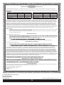
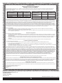
Limited Warranty
SENCO® Pneumatic, DuraSpin®, Cordless Tools
& Compressors
KYOCERA-SENCO Industrial Tools, Inc. (“SENCO”) designs and constructs its products using the highest standards of material and workmanship.
SENCO warrants to the original retail purchaser that the following products will be free from defects in material or workmanship for the warranty period
Products New Reconditioned Products New Reconditioned
Pneumatic Tools ÜFive Years One Year Air Compressors One Year 90 Days
Fusion Tools Two Years Six Months Combo Kit Tools One Year 90 Days
Gas Tools Two Years Six Months Multi-Blow Hand Nailers One Year 90 Days
Duraspin Tools Five Years 90 Days Stapling Hammers One Year 90 Days
Ü = Both XP and Pro Series
During the warranty period (which begins on the purchase date), SENCO will repair or replace, at SENCO’s option and expense, any product or part
that is defective in materials or workmanship after examination by a SENCO Authorized Warranty Service Centre, subject to the exceptions, exclusions
and limitations described below. Any replacement product or part will carry a warranty for the balance of the warranty period applicable to the replaced
product or part. A DATED SALES RECEIPT OR PROOF OF PURCHASE FROM THE ORIGINAL RETAIL PURCHASER IS REQUIRED TO MAKE A
WARRANTY CLAIM. Warranty registration is also required and can be accomplished through on-line Product Registration at www.senco.com or by
completing and returning the postage paid warranty registration form included with your Operator’s manual/parts chart information, found inside the
product carton. To make a warranty claim, you must return the product, with proper receipt/proof of purchase and return transportation charges prepaid,
to a SENCO Authorized Warranty Service Centre. A list of SENCO Authorized Warranty Service Centres can be found at www.senco.com or by calling
1-800-543-4596 toll free. SENCO will perform its obligations under this warranty within a reasonable time after approval of the warranty claim.
SENCO Cordless:
1. Subject to the exceptions, exclusions and limitations described below, SENCO warrants that the SENCO Cordless tool will be free from defects
in materials and workmanship for two years after the purchase date.
2. SENCO warrants that the batteries and chargers used with SENCO Cordless tools will be free from defects in material and workmanship for
one year after the purchase date.
Warranty Exclusions
The following warranty exclusions apply:
1.
seals, driver blades, piston stops, and piston/driver assembly.
2. This warranty does not cover parts damaged due to normal wear, misapplication, misuse, accidents, operation beyond the recommended
speeds or voltage (electric units only), improper storage, or damage resulting from shipping.
3. Prod
4. Labour charges or loss or damage resulting from improper operation, maintenance or repairs are not covered by this warranty.
General Warranty Conditions
This warranty will be honoured only if:
A. Clean, dry, regulated compressed air has been used, at air pressure not exceeding the maximum indicated on the tool casting;
B. No e
C. No d
maintenance instructions).
THIS WARRANTY IS THE ONLY WARRANTY ON THE PRODUCT, AND SENCO DISCLAIMS ALL OTHER WARRANTIES. ANY IMPLIED WAR-
RANTIES WILL BE LIMITED IN DURATION TO THE APPLICABLE WARRANTY PERIOD SPECIFIED ABOVE. SOME STATES DO NOT ALLOW
LIMITATIONS ON HOW LONG AN IMPLIED WARRANTY LASTS, SO THE ABOVE LIMITATION MAY NOT APPLY TO YOU. YOUR REMEDIES ARE
SOLELY AND EXCLUSIVELY AS STATED ABOVE. SENCO SHALL IN NO EVENT BE LIABLE FOR INCIDENTAL, CONSEQUENTIAL, INDIRECT,
OR SPECIAL DAMAGES. SOME STATES DO NOT ALLOW THE EXCLUSION OR LIMITATION OF INCIDENTAL OR CONSEQUENTIAL DAMAGES,
SO THE ABOVE LIMITATION OR EXCLUSION MAY NOT APPLY TO YOU. IN NO EVENT, WHETHER AS A RESULT OF A BREACH OF CONTRACT,
WARRANTY, TORT (INCLUDING NEGLIGENCE) OR OTHERWISE, SHALL SENCO’S LIABILITY EXCEED THE PRICE OF THE PRODUCT WHICH
HAS GIVEN RISE TO THE CLAIM OR LIABILITY. ANY LIABILITY CONNECTED WITH THE USE OF THIS PRODUCT SHALL TERMINATE UPON THE
EXPIRATION OF THE WARRANTY PERIOD SPECIFIED ABOVE. NO EMPLOYEE OR REPRESENTATIVE OF SENCO OR ANY DISTRIBUTOR OR
DEALER IS AUTHORIZED TO MAKE ANY CHANGE OR MODIFICATION TO THIS WARRANTY.
Replacement of Tool Due to Natural Disaster
Such a claim will be honoured provided that the original retail purchaser had previously submitted a completed warranty registration card for the tool,
and then submits proof of ownership and an acceptable statement describing such Act of God documented by an insurance carrier, police department,
Customer Satisfaction
If for any reason the product does not perform to the original purchaser’s satisfaction, it can be returned to the place of purchase within thirty days with
dated sales receipt for a full refund of the purchase price (applies to new product sales only).
© 2019 KYOCERA-SENCO Industrial Tools, Inc.
CINCINNATI, OHIO 45244-1611 USA
www.senco.com
160101
15

KYOCERA-SENCO Industrial Tools, Inc.
8450 Broadwell Road
Cincinnati, Ohio 45244
1-800-543-4596
www.senco.com

FN81T1 / FN91T1
CLAVADORAS NEUMÁTICAS
PARA ESTRUCTURAS
Instrucciones de operación
NFD8FN81TFN91T • Emitido el 4 de octubre de 2021
IMPORTANTE:
Lea este documento antes
de utilizar la herramienta.
KYOCERA-SENCO Industrial Tools, Inc.
8450 Broadwell Road
Cincinnati, OH 45244
1-800-543-4596
www.senco.com © 2021 by KYOCERA-SENCO Industrial Tools, Inc.
Warnings for the safe use of this tool are included in this manual.
En este manual se incluyen advertencias para utilizar esta herramienta de manera segura.
Les consignes pour l’utilisation en toute sécurité de cet outil se trouvent dans ce manuel.

Índice
Responsabilidades del empleador .............................................................................................................. 2
Advertencias de seguridad ......................................................................................................................... 3
Mantenimiento ........................................................................................................................................... 7
Operación funcional (FN81T1) ................................................................................................................... 8
Operación funcional (FN91T1) ................................................................................................................... 9
Uso de la herramienta .............................................................................................................................. 10
Sistema de accionamiento ....................................................................................................................... 10
Despejar un atasco ................................................................................................................................... 11
Funciones ................................................................................................................................................. 11
Solución de problemas ............................................................................................................................ 12
Accesorios ............................................................................................................................................... 13
Opciones .................................................................................................................................................. 13
Especificaciones técnicas ......................................................................................................................... 13
Especificaciones de los sujetadores ......................................................................................................... 14
Garantía limitada ...................................................................................................................................... 15
Responsabilidades del empleador
Mantenga este manual disponible para que lo consulten todas las personas que utilicen esta herramienta.
El empleador debe hacer cumplir las advertencias de seguridad y todas las demás instrucciones que
vienen con esta herramienta tal como la envió el fabricante.
El sistema de accionamiento de la herramienta debe ser adecuado tomando en consideración la aplica-
ción para la que se utiliza.
El operador debe recibir capacitación para utilizar con seguridad la herramienta como se describe en el
manual de operación segura.
Para utilizar la herramienta, es necesario que quien lo haga haya leído y entienda las instrucciones de
operación segura.
2

3
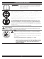
ADVERTENCIAS DE SEGURIDAD
WARNING
Lea y comprenda las etiquetas y el manual de la herramienta.
No seguir las advertencias provocará la MUERTE o LESIONES
GRAVES.
Guarde estas instrucciones.
Equipo de protección personal
Use equipo de seguridad. Siempre use gafas de seguridad ANSI Z87+ con protectores laterales
permanentemente colocados. En las condiciones adecuadas, se debe usar una mascarilla
antipolvo, zapatos de seguridad antideslizantes, casco o protección auditiva. De no hacerlo, la
persona podría sufrir lesiones. El operador y otras personas en el área de trabajo deben usar
equipo de protección para los ojos.
El empleador es responsable de hacer que el operador de la herramienta y todo el personal en
el área de trabajo cumplan con el uso de equipo de protección personal.
La protección para los ojos debe cumplir con los requisitos de ANSI Z87+ y brindar protección
contra partículas voladoras en el frente y en los lados.
La protección auditiva debe tener una clasificación de reducción de ruido determinada de
acuerdo con las reglas de la Agencia de Protección Ambiental de Estados Unidos que sea
apropiada para la exposición al ruido.
La protección para la cabeza debe cumplir con ANSI Z89.1.
Riesgo de explosión
Nunca use la herramienta en atmósferas explosivas ni en presencia de materiales combustibles como polvo,
gases o líquidos inflamables.
Peligroso
Nunca use oxígeno, dióxido de carbono o cualquier otro gas envasado como fuente
de energía para esta herramienta; la herramienta explotará y provocará lesiones
graves.
No se deben utilizar fuentes de energía peligrosas. Puede ocurrir una explosión.
Las fuentes de energía peligrosas incluyen, entre otras:
1. Gases reactivos, por ejemplo, oxígeno y gases combustibles.
2. Fuentes de presión que pueden brindar más de 1.5 veces la presión de aire
máxima de la herramienta o 200 psig (13.8 bares), lo que sea mayor, si falla un
regulador.

ADVERTENCIAS DE SEGURIDAD
Sistemas de disparo
Seleccione siempre un sistema de accionamiento que sea apropiado para la aplicación de sujetadores y la
capacitación del operador de la herramienta.Póngase en contacto con Senco en www.senco.com para obtener
información sobre las opciones del sistema de accionamiento.
Las herramientas se fabrican con diferentes sistemas de disparo según la aplicación de la herramienta, el tamaño
del sujetador y la preferencia del operador. Lea las instrucciones de operación para familiarizarse con el funcio-
namiento de cada tipo de sistema de disparo.
• Se prefiere un mecanismo de accionamiento secuencial cuando se desea la colocación exacta del sujetador o el
empleador / operador prefiere que la herramienta se reajuste cada vez que se coloque un sujetador. Los controles
operativos deben activarse en una secuencia específica para activar la herramienta. Si la herramienta tiene un dispara-
dor y un contacto de la pieza de trabajo, el contacto de la pieza de trabajo debe activarse antes que el disparador para
que la herramienta funcione. Este tipo de disparador se identifica fácilmente en su herramienta SENCO porque es de
color GRIS.
• Cuando se desea colocar rápidamente los sujetadores, la opción es un mecanismo de accionamiento por contacto.
Este sistema de accionamiento se puede activar en cualquier secuencia. La herramienta se puede activar nuevamente
cuando se suelta y se reactiva cualquier control operativo. Este tipo de disparador se identifica fácilmente en su
herramienta SENCO porque es de color NEGRO.
• Algunas herramientas tienen una opción de disparo seleccionable integrada en el mecanismo de disparo. Estas he-
rramientas se pueden cambiar entre operación secuencial y accionamiento por contacto moviendo un botón, palanca
o interruptor. Consulte el manual del operador para determinar si este disparador seleccionable está incluido en su
herramienta de colocación de sujetadores. Este tipo de disparador se identifica fácilmente en su herramienta SENCO
porque es de color ROJO o porque el disparador es de color NEGRO y el interruptor es de color ROJO.
• Las herramientas de trabajo ligero pueden tener solo un disparador manual y no requieren un elemento de contacto
de trabajo. Estas herramientas se utilizan en aplicaciones especializadas y normalmente se utilizan en aplicaciones
industriales.
• Las herramientas de trabajo ligero pueden tener un disparador de acción dual. El disparador de dos etapas debe
accionarse en una secuencia a fin de colocar un sujetador. Este tipo de herramienta no requiere un elemento de
contacto de trabajo y se utiliza para aplicaciones especializadas.
• Algunas herramientas para aplicaciones especializadas utilizan un mecanismo de contacto de pieza de trabajo retraí-
do. Estas herramientas se utilizan para sujetar una correa a una placa utilizando orificios previamente perforados. *La
designación del color del disparador no se aplica al conector de metal.
Se recomienda que los operadores que tienen menos experiencia en el uso de herramientas neumáticas de colocación de
sujetadores elijan un mecanismo secuencial hasta que se familiaricen con la herramienta y su funcionamiento.
Llame al Servicio de atención al cliente de Senco para obtener otro tipo de disparador en las herramientas que el usuario
pueda modificar para adaptarse a la aplicación o al nivel de experiencia del operador.
4
La page charge ...
La page charge ...
La page charge ...
La page charge ...
La page charge ...
La page charge ...
La page charge ...
La page charge ...
La page charge ...
La page charge ...
La page charge ...
La page charge ...
La page charge ...
La page charge ...
La page charge ...
La page charge ...
La page charge ...
La page charge ...
La page charge ...
La page charge ...
La page charge ...
La page charge ...
La page charge ...
La page charge ...
La page charge ...
La page charge ...
La page charge ...
La page charge ...
-
 1
1
-
 2
2
-
 3
3
-
 4
4
-
 5
5
-
 6
6
-
 7
7
-
 8
8
-
 9
9
-
 10
10
-
 11
11
-
 12
12
-
 13
13
-
 14
14
-
 15
15
-
 16
16
-
 17
17
-
 18
18
-
 19
19
-
 20
20
-
 21
21
-
 22
22
-
 23
23
-
 24
24
-
 25
25
-
 26
26
-
 27
27
-
 28
28
-
 29
29
-
 30
30
-
 31
31
-
 32
32
-
 33
33
-
 34
34
-
 35
35
-
 36
36
-
 37
37
-
 38
38
-
 39
39
-
 40
40
-
 41
41
-
 42
42
-
 43
43
-
 44
44
-
 45
45
-
 46
46
-
 47
47
-
 48
48


Senco FN81T1 Manuel utilisateur
- Catégorie
- Cloueuse
- Taper
- Manuel utilisateur
dans d''autres langues
- English: Senco FN81T1 User manual
- español: Senco FN81T1 Manual de usuario
Documents connexes
-
Senco FramePro 701XP Le manuel du propriétaire
-
Senco FramePro 702XP Le manuel du propriétaire
-
-
-
-
-
-