Aiwa ACD-24KBTU Manuel utilisateur
- Catégorie
- Climatiseurs split-system
- Taper
- Manuel utilisateur

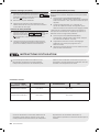
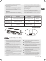
INSTRUCTION MANUAL , INSTALLATION, FEATURES EN
GEBRAUCHSANWEISUNG, INSTALLATION, AUSSTATTUNG DE
MANUAL DE INSTRUCCIONES , INSTALACIÓN, CARACTERÍSTICAS ES
MANUEL D'INSTRUCTION, INSTALLATION, CARACTÉRISTIQUE FR
MANUALE DI ISTRUZIONI, INSTALLAZIONE, CARATTERISTICA IT
INSTRUKCJA OBSŁUGI, INSTALACJA, FUNKCJE PL
ACD-24KBTU
MINI-SPLIT AIR CONDITIONER
INVERTER WITH SMART CONTROL & REMOTE CONTROL


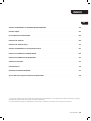
INDEX
.......................................................................................................................................................................................................................................................................................................................
NAME OF PARTS .............................................................................................................................................................................................................................................................................................................................................. 6
REMOTE CONTROL .....................................................................................................................................................................................................................................................................................................................................8
...................................................................................................................................................................................................................................................................................................
...................................................................................................................................................................................................................................................................
............................................................................................................................................................................................................................................................................................17
............................................................................................................................................................................................................................................................................................
.....................................................................................................................................................................................................................................................................................
TEST OPERATION .......................................................................................................................................................................................................................................................................................................................................
MAINTENANCE ...............................................................................................................................................................................................................................................................................................................................................
............................................................................................................................................................................................................................................................................................................................
.....................................................................................................................................................................................................................................................................
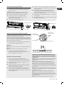
*The design and specications are subject to change without prior notice for product improvement. Consult with the sales agency
or manufacturer for details.
* The shape and position of buttons and indicators may vary according to the model, but their function are the same.

ACD-24KBTU
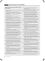
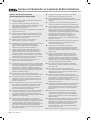
INSTALLER
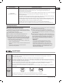
1. Read this guide before installing and using the
appliance.
During the installation of the indoor and outdoor
units, access to the working area should be forbidden
to children. Unforeseeable accidents could happen.
.Make sure that the base of the outdoor unit is rmly
xed.
Check that air cannot enter the refrigerant system
and check for refrigerant leaks when moving the air
conditioner.
5. Carry out a test cycle after installing the air
conditioner and record the operating data.
6. Protect the indoor unit with a fuse of suitable capacity
for the maximum input current or with another
overload protection device.
7. Ensure that the mains voltage corresponds to that
stamped on the rating plate. Keep the switch or power
plug clean. Insert the power plug correctly and rmly
into the socket, thereby avoiding the risk of electric
shock or re due to insufcient contact.
8. Check that the socket is suitable for the plug ,
otherwise have the socket changed.
The appliance must be tted with means for
disconnection from the supply mains having a contact
separation in all poles that provide full disconnection
under over voltage category III conditions, and these
means must be incorporated in the xed wiring in
accordance with the wiring rules.
The air conditioner must be installed by professional
or qualied persons.
11. Do not install the appliance at a distance of less than
50 cm from inammable substances(alcohol, etc.) Or
from pressurized containers (e.g. spray cans).
If the appliance is used in areas without the
possibility of ventilation, precautions must be taken to
prevent any leaks of refrigerant gas from remaining in
the environment and creating a danger of re.
The packaging materials are recyclable and should
be disposed of in the separate waste bins. Take the
air conditioner at the end of its useful life to a special
waste collection center for disposal.
Only use the air conditioner as instructed in this
booklet. These instructions are not intended to cover
every possible condition and situation. As with any
electrical household appliance, common sense and
caution are therefore always recommended for
installation, operation and maintenance.
15. The appliance must be installed in accordance with
applicable national regulations.
16. Before accessing the terminals, all the power circuits
must be disconnected from the power supply.
17. The appliance shall be installed in accordance with
national wiring regulations.
18. This appliance can be used by children aged from 8
years and above and persons with reduced physical,
sensory or mental capabilities or lack of experience
and knowledge if they have been given supervision or
instruction concerning use of the appliance in a safe
way and understand the hazards involved. Children
shall not play with the appliance. Cleaning and user
maintenance shall not be made by children without
supervision.
Do not try to install the conditioner alone, always
contact specialized technical personnel.
Cleaning and maintenance must be carried out by
specialized technical personnel. In any case disconnect
the appliance from the mains electricity supply before
carrying out any cleaning or maintenance.
Ensure that the mains voltage corresponds to that
stamped on the rating plate. Keep the switch or power
plug clean. Insert the power plug correctly and rmly
into the socket, thereby avoiding the risk of electric
shock or re due to insufcient contact.
Do not pull out the plug to switch off the appliance
when it is in operation, since this could create a spark
and cause a re, etc.
This appliance has been made for air conditioning
domestic environments and must not be used for any
other purpose, such as for drying clothes, cooling food,
etc.
Always use the appliance with the air lter mounted.
The use of the conditioner without air lter could
cause an excessive accumulation of dust or waste on
the inner parts of the device with possible subsequent
failures.
The user is responsible for having the appliance
installed by a qualied technician, who must check
that it is earth in accordance with current legislation
and insert a thermos magnetic circuit breaker.
The batteries in the remote controller must be
recycled or disposed of properly. For disposal of
scrap batteries, please discard the batteries as sorted
municipal waste at the accessible collection point.
Never remain directly exposed to the ow of cold air
for a long time. The direct and prolonged exposition to
cold air could be dangerous for your health. Particular
care should be taken in the rooms where there are
children, old or sick people.
If the appliance gives off smoke or there is a smell
of burning, immediately cut off the power supply and
contact the Service Center.
The prolonged use of the device in such conditions
could cause re or electrocution.
Have repairs carried out only by an authorised
Service Centra of the manufacturer. Incorrect repair
could expose the user to the risk of electric shock, etc.
Unhook the automatic switch if you foresee not to
use the device for a long time. The airow direction
must be properly adjusted.
The aps must be directed downwards in the
heating mode and upwards in the cooling mode.
Ensure that the appliance is disconnected from the
power supply when it will remain inoperative for a
long period and before carrying out any cleaning or
maintenance.
Selecting the most suitable temperature can prevent
damage to the app

ACD-24KBTU 5
EN
INSTALLER
1. Do not bend, tug or compress the power cord since
this could damage it. Electrical shocks or re are
probably due to a damaged power cord. Specialized
technical personnel only must replace a damaged
power cord.
Do not use extensions or gang modules.
Do not touch the appliance when barefoot or parts
of the body are wet or damp.
Do not obstruct the air inlet or outlet of the indoor or
the outdoor unit. The obstruction of these openings
causes a reduction in the operative efciency of the
conditioner with possible consequent failures or
damages.
5. In no way alter the characteristics of the appliance.
6. Do not install the appliance in environments where
the air could contain gas, oil or sulphur or near
sources of heat.
7. This appliance is not intended for use by persons
(including children ) with reduced physical, sensory
or mental capabilities, or lack of experience and
knowledge, unless they have been given supervision
or instruction concerning use of the appliance by a
person responsible for their safety.
8. Do not climb onto or place any heavy or hot objects
on top of the appliance.
Do not leave windows or doors open for long when
the air conditioner is operating.
Do not direct the airow onto plants or animals.
11. A long direct exposition to the ow of cold air of the
conditioner could have negative effects on plants
and animals.
Do not put the conditioner in contact with water.
The electrical insulation could be damaged and thus
causing electrocution.
Do not climb onto or place any objects on the
outdoor unit.
Never insert a stick or similar object into the
appliance. It could cause injury.
15. Children should be supervised to ensure that they
do not play with the appliance. If the supply cord is
damaged, it must be replaced by the manufacturer,
its service agent or similarly qualied persons in
order to avoid a hazard.

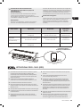
6 ACD-24KBTU
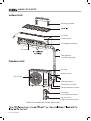
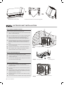
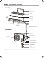
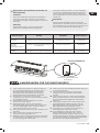
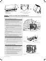
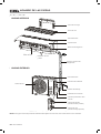
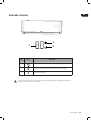
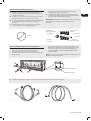
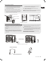
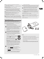
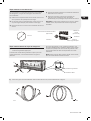
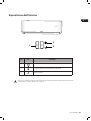
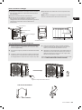
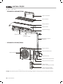
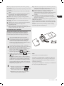
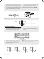
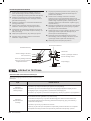
Refrigerant
connecting pipe
Indoor Unit
Out
door Unit
Mounting plate
Air inlet
Front panel
Emergency button
Air inlet
Wiring cover
Drainage pipe
Connection wiring
Valve protective cover
Gas valve
(Low pressure valve)
Liquid valve
(High pressure valve)
Air outlet
Air outlet
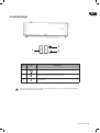
With the protective cover removed
NAME OF PARTS

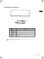
ACD-24KBTU 7
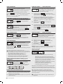
EN
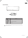
Indoor Display
1
NO LED
1Indicator for Timer, temperature and Error codes.
2Lights up during Timer operation.
3SLEEP mode
The shape and position of switches and indicators may be different according to the model,
but their function is the same.

8 ACD-24KBTU
5
6 1
17
8
18
15
16
11
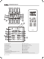
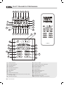
1) Battery indicator
Auto Mode
Cooling Mode
Dry Mode
5) Fan only Mode
6) Heating Mode
7) ECO Moder
8) Timer
Temperature indicator
Fan speed: Auto/low/ low-mid/ mid/ mid-high/ high
11) Mute function
TURBO function
Up-down auto swing
Left-right auto swing
15) SLEEP function
16) Health function
17) I FEEL function
18) 8ºC heating function
Signal indicator
Gentle wind
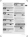
REMOTE CONTROLLER

ACD-24KBTU
EN
Child-Lock
Display ON/OFF
To turn on/off the air conditioner.
To increase temperature, or Timer setting hours.
To decrease temperature, or Timer setting hours.
MODE To select the mode of operation (AUTO,
COOL, DRY, FAN, HEAT).
ECO To activate/deactivate the ECO function.
Long press to activate/deactivate the 8ºC heating
function (depending on models).
TURBO To activate/deactivate the TURBO function.
FAN To select the fan speed of auto/low/mid/high.
TIMER To set the time for timer on/off.
SLEEP To switch-on/off the function SLEEP.
DISPLAY To switch-on/off the LED display.
SWING To stop or start horizontal aps louver
movement or set the desired up/down air ow
direction.
SWING To stop or start vertical deectors louver
movement or set the desired left/right air ow
direction.
I FEEL To switch-on/off the I FEEL function.
MUTE To switch-on/off the MUTE function. Long
press to activate/deactivate the GEN function
(depending on models).
I SET To memory the setting temperature, setting
mode and setting fan speed as you need.
The display and some functions of the remote control
may vary according to the model.
The shape and position of buttons and indicators may
vary according to the model, but their function is the
same.
The unit conrms the correct reception of each button
with the beep.
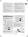
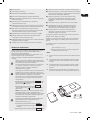
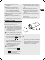
Remove the battery cover plate from the rear of the
remote control, by sliding it in direction as the arrow.
Install the batteries according the direction (+ and -)
shown on the Remote Control.
Reinstall the battery cover by sliding it into place.
Use 2 pieces LRO3 AAA (1.5V) batteries.
Do not use rechargeable batteries.
Replace the old batteries with new ones of the
same type when the display is no longer legible.
Do not dispose batteries as unsorted municipal
waste. Collection of such waste separately for
special treatment is necessary.
For some model, each time when insert the
batteries in the remote controller for the rst
time, you can set the Cooling only or Heating
pump control type. As soon as you insert the
batteries, turn off the remote controller, and
operate as below.
1. Long press the MODE button, until the ( )
icon ash, to set the Cooling only type.
Long press the MODE button, until the ( )
icon azsh, to set the Heating pump type.
Note: If you set the remote control in cooling
mode, it will not be possible to activate the
heating function in units with a heating pump.
If you need to reset, take out the batteries and
install again.
For some models of the remote controller, you
can program the temperature display between
ºC and ºF.
1. Press and hold the ,button over 5
seconds to get into the change mode;
Press and hold the until it switch to
ºC and ºF.;
Then release the pressing and wait for 5
seconds, the function will be selected.z
Note:
1. Direct the remote control toward the Air conditioner
Check that there are no objects between the remote
control and the Signal receptor in the indoor unit.
Never leave the remote control exposed to the rays
of the sun.
Keep the remote control at a distance of at least 1m
from the television or other electrical appliances.

ACD-24KBTU
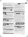
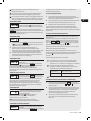
COOL
The cooling function allows the air
conditioner to cool the room and reduce
Air humidity at the same time.
To activate the cooling function (COOL), press the
MODE button until the symbol appears on the
display.
With the button or set a temperature lower
than that of the room.
FAN MODE (Not FAN button)
FAN Fan mode, air ventilation only.
To set the FAN mode, press MODE until
appears on the display.
DRY MODE
DRY This function reduces the humidity
of the air to make the room more
comfortable.
To set the DRY mode, Press MODE until appears
in the display. An automatic function of pre-setting is
activated.
Automatic mode.
To set the AUTO mode, press MODE
until appears on the display.
In AUTO mode the run mode will be set
automatically according to the room temperature.
The heating function allows the air
conditioner to heat the room.
To activate the heating function (HEAT),
press the MODE button until the symbol appears on
the display.
With the button or set a temperature higher than that
of the room.
In HEATING operation, the appliance can
automatically activate a defrost cycle, which
is essential to clean the frost on the condenser
so as to recover its heat exchange function.
This procedure usually lasts for 2-10 minutes.
During defrosting, indoor unit fan stop
operation. After defrosting, it resumes to
HEATING mode automaticall
FAN SPEED function (FAN button)
FAN
Change the operating fan speed.
Press button FAN to set the running fan
speed,
it can be set to AUTO/ MUTE/ LOW/ LOW-MID
/ MID/ MID-HIGH/ HIGH/ TURBO speed circularly.
1. Long press MODE and TIMER button together to
active this function, and do it again to desactivate
this function.
Under this function, no single button will active.
TIMER function ---- TIMER ON
TIMER To automatic switch on the appliance.
When the unit is switch-off, you can set
the TIMER ON.
To set the time of automatic switch-on as below:
1. Press TIMER button rst time to set the switch-on,
and will appear on the remote display and
ashes.
Press or to button to set desired Timer-on time.
Each time you press the button, the time increases/
decreases by half an hour between 0 and 10 hours
and by one between 10 and 24 hours.
Press TIMER button second time to conrm.
After Timer-on setting, set the needed mode (Cool/
Heat/ Auto/ Fan/ Dry), by press the MODE button.
And set the needed fan speed, by press FAN
button. And press or to set the needed operation
temperature.
CANCEL it by press TIMER button.
TIMER function ---- TIMER OFF
TIMER To automatic switch off the appliance.
When the unit is switch-off, you can set
the TIMER ON.
To set the time of automatic switch-on as below:
When the unit is switch-on, you can set the TIMER OFF.
1. Conrm the appliance is ON.
Press the TIMER button at rst time to set the
switch-off.
Press TIMER button at the second time to conrm.
CANCEL it by press TIMER button.
Note: All programming should be operated within 5
seconds, otherwise the setting will be
cancelled.
1. Press the button SWING to activate the louver,
1.1 Press to activate the horizontal aps to
swing from up to down, the will appear on the
remote display. Press again to stop the swing
movement at the current angle.
Press to active the vertical deectors to
swing from left to right, the will appear on the
remote display.
Press again to stop the swing movement at the
current angle.
If the vertical deectors are positioned manually
which placed under the aps, they allow to move the air
ow direct to rightward or leftward.
For some inverter heating models, press horizontal
SWING and vertical SWING together button at the same
time, it will activate the Self-Clean function.

ACD-24KBTU 11
EN
This adjustment must be done while the appliance is
switched off
Never position Flaps manually, the delicate
mechanism might seriously damaged!
Never put ngers, sticks or other objects into the air
inlet or outlet vents. Such accidental contact with
live parts might cause unforeseeable damage or
injury.
TURBO To activate turbo function, press the
TURBO button, and will appear on
the display.
Press again to cancel this function.
In COOL/ HEAT mode, when you select feature,
the appliance will turn to quick COOL or quick HEAT
mode, and operate the highest fan speed to blow
strong airow.
1. Press button to active this function, and
will appears on the remote display. Do it again to
deactivate this function.
When the MUTE function runs, the remote
controller will display the auto fan speed, and the
indoor unit will operate at lowest fan speed to be
quiet feeling.
When press FAN/ TURBO/ SLEEP button, the MUTE
function will be cancel. MUTE function can not be
activated under dry mode.
SLEEP function
SLEEP Pre-setting automatic operating
program.
Press SLEEP button to activate the
SLEEP function, and appears on the display. Press
again to cancel this function.
After 10 hours running in sleep mode, the air
conditioner will change to the previous setting
mode.
I FEEL function (Optional)
I FEEL Press I FEEL button to active the
function, the will appear on the remote
display. Do it again to deactivate this
function.
This function enables the remote control to measure
the temperature at its current location, and send this
signal to the air conditioner to optimize the temperature
around you and ensure the comfort.
It will automatically deactivate 2 hours later.
ECO function
ECO
In this mode the appliance automatically
sets the operation to save energy.
Press the ECO button, the appears on
the display, and the appliance will run in ECO mode.
Press again to cancel it.
Note: The ECO function is available in both
COOLING and HEATING modes.
DISPLAY function
DISPLAY Switch ON/OFF the LED display on panel.
Press DISPLAY button to switch off the
LED display on the panel. Press again to
switch on the LED display.
1. Turn on the indoor unit at rst, and long press
MUTE button 3 seconds to active, and do it again to
deactivate this function.
Under this function, short press MUTE button to
select the General type L3 - L2 - L1 - OF.
Select OF and wait 2 seconds to exit it.
* If the indoor unit displays "0A", please use the remote
to raise the operating gear of the GEN mode, and the
compressor will restart after stopping for 3 minutes.
SELF-CLEAN function (Optional)
Only optional for some heating pump inverter
appliance.
To active this function, turn off the indoor unit at rst,
then press and button at the same time
toward the indoor unit, until hear a beep, and
AC
will
appear on the remote controller display and the indoor
LED display.
1. This function helps carry away the accumulated dirt,
bacteria, etc from the indoor evaporator.
This function will run about 30 minutes, and it will
return to the pre-setting mode. You can press button
to cancel this function during the process.
You will hear 2 beeps when it's nished or cancelled.
It's normal if there is some noise during this
function process, as plastic materials expand with
heat and contract with cold.
We suggest operating this function at the
following ambient conditions to avoid certain
safety protection features.
It's suggested to utilize this function every
3 months.
function (Optional)
1. Long press ECO button over 3 seconds to active
this function, and 8ºC ( 46ºF ) will appear on the
remote display.
Do it again to deactivate this function 8ºC 46ºF This
function will auto start the heating mode when the
room temperature is lower than 8ºC (46ºF), and it
will return to standby if the temperature reaches
9ºC (48ºF).
If the room temperature is higher than 18ºC
(64ºF), the appliance will cancel this function
automatically.
Indoor unit Temp < 86ºF (30ºC)
Outdoor unit 41ºF (5ºC) < Temp < 86ºF(30ºC)

ACD-24KBTU
1. Turn on the indoor unit, and change to COOL mode,
then long press FAN and button together 3
seconds to active this function, will appear on the
display. Do it again to deactivate it.
This function will auto close the vertical aps, and
give you the comfortable gentle wind feeling.
1. Turn on the indoor unit at rst, and long press
SLEEP and DISPLAY button together 3 seconds to
active this function, will appear on the display.
Do it again to deactivate it
When the HEALTH function is initiated, the Ionizer/
Plasma/ Bipolar Ionizer/ UVC Lights (depending on
models) will be energized and running.
I SET function (Optional)
Remember your favorite setting and run into it by press
One button Remember the favorite setting:
1. In each mode (COOLING/ HEATING/ FAN/ DRY),
long press " I SET " button over 3 seconds to
remember it;
When "AU" ashing appears on the remote
controller display, that means the remote controller
remember your favorite setting;
* Press any button to quit, and you can reset it by repeat
1, 2 operation.
Run into the favorite setting:
1. In each mode (COOLING/ HEATING/ FAN/ DRY), one
press " I SET " button to active;
The appliance will run as your favorite setting and
you will see [AU] ashing on the remote controller;
Press it again or other buttons to cancel this
function.
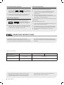
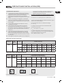
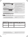
Attempt to use the air conditioner under the
temperature beyond the specied range may cause
the air conditioner protection device to start and the
air conditioner may fail to operate. Therefore, try to
use the air conditioner in the following temperature
conditions.
With the power supply connected, restart the air
conditioner after shutdown, or switch it to other
mode during operation, and the air conditioner
protection device will start. The compressor will
resume operation after 3 minutes.
Dry
Room temperature 0 ºC~30ºC 17ºC ~32ºC
Outdoor temperature -20ºC~30ºC -15ºC~53ºC
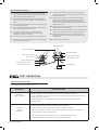
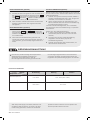
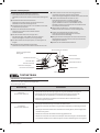
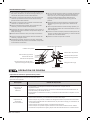
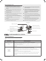
Temperature MODE
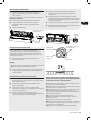
Inverter air conditioner:

Current status Operation Respond Enter mode
Standby Press the emergency button once It beeps briey once. Cooling mode
Standby
(Only for heating
pump)
Press the emergency button twice in
3 seconds
It beeps briey twice. Heating mode
Running Press the emergency button once It keeps beeping for a
while
Off mode
(open the panel of indoor unit)
ACD-24KBTU
EN
When the heating function is enabled, the indoor
unit will take 2~5 minutes for preheating, after
that the air conditioner will start heating and blow
s warm air.
During heating, when the outdoor unit frosted, the
air conditioner will enable the automatic
defrosting function to improve the heating effect.
During defrosting, the indoor and outdoor fans
stop running. The air conditioner will resume
heating automatically after defrosting nish.
Open the panel and nd the emergency button on
the electronic control box when the remote
controller fails . (Always press the emergency button
with insulation material.)
1. Check the information in this manual to nd out the
dimensions of space needed for proper installation
of the device, including the minimum distances
allowed compared to adjacent structures.
Appliance shall be installed, operated and stored in
a room with a oor area larger than 4m2.
The installation of pipe-work shall be kept to a
minimum.
The pipe-work shall be protected from physical
damage, and shall not be installed in an
unventilated space if the space is smaller than 4m2.
5. The compliance with national gas regulations shall
be observed.
6. The mechanical connections shall be accessible for
maintenance purposes.
7. Follow the instructions given in this manual for
handling, installing, cleaning, maintaining and
disposing of the refrigerant.
8. Make sure ventilation openings clear of obstruction.
Notice: The servicing shall be performed only as
recommended by the manufacturer.
The appliance shall be stored in a well-
ventilated area where the room size corresponds to
the room area as specied for operation.
11. The appliance shall be stored in a room
without continuously operating open ames (for
example an operating gas appliance) and ignition
sources (for example an operating electric heater).
The appliance shall be stored so as to prevent
mechanical damage from occurring.
It is appropriate that anyone who is called upon to
work on a refrigerant circuit should hold a valid and

ACD-24KBTU
up-to-date certicate from an assessment authority
accredited by the industry and recognizing their
competence to handle refrigerants, in accordance
with the assessment specication recognized in
the industrial sector concerned. Service operations
should only be carried out in accordance with the
recommendations of the equipment manufacturer.
Maintenance and repair operations that require
the assistance of other qualied persons must be
conducted under the supervision of the person
competent for the use of ammable refrigerants.
Every working procedure that affects safety means
shall only be carried out by competent persons.
15.
* Do not use means to accelerate the defrosting
process or to clean, other than those
recommended by the manufacturer.
* The appliance shall be stored in a room without
continuously operating ignition sources (for
example: open ames, an operating gas
appliance or an operating electric heater).
* Do not pierce or burn.
* Be aware that refrigerants may not contain an
odor.
16. Information on servicing:
1) Checks to the area Prior to beginning work on
systems containing ammable refrigerants, safety
checks are necessary to ensure that the risk of
ignition is minimized. For repair to the refrigerating
system, the following precautions shall be complied
with prior to conducting work on the system.
Work procedure Work shall be undertaken under
a controlled procedure so as to minimize the risk of
a ammable gas or vapor being present while the
work is being performed.
General work area All maintenance staff and
others working in the local area shall be instructed
on the nature of work being carried out. Work in
conned spaces shall be avoided. The area around
the workspace shall be sectioned off. Ensure that
the conditions within the area have been made safe
by control of ammable material
Checking for presence of refrigerant The area
shall be checked with an appropriate refrigerant
detector prior to and during work, to ensure the
technician is aware of potentially ammable
atmospheres. Ensure that the leak detection
equipment being used is suitable for use with
ammable refrigerants, i.e. non-sparking,
adequately sealed or intrinsically safe.
5) Presence of re extinguisher If any hot work is
to be conducted on the refrigeration equipment or
any associated parts, appropriate re extinguishing
equipment shall be available to hand. Have a dry
powder or CO 2 re extinguisher adjacent to the
charging area.
6) No ignition sources No person carrying out
work in relation to a refrigeration system which
involves exposing any pipe work shall use any
sources of ignition in such a manner that it may
lead to the risk of re or explosion. All possible
ignition sources, including cigarette smoking,
should be kept sufciently far away from the site
of installation, repairing, removing and disposal,
during which refrigerant can possibly be released to
the surrounding space. Prior to work taking place,
the area around the equipment is to be surveyed to
make sure that there are no ammable hazards or
ignition risks. No Smoking signs shall be displayed.
7) Ventilated area Ensure that the area is in the open
or that it is adequately ventilated before breaking
into the system or conducting any hot work. A
degree of ventilation shall continue during the
period that the work is carried out.
The ventilation should safely disperse any released
refrigerant and preferably expel it externally into the
atmosphere.
8) Checks to the refrigeration equipment Where
electrical components are being changed, they
shall be t for the purpose and to the correct
specication. At all times the manufacturer's
maintenance and service guidelines shall be
followed.
If in doubt consult the manufacturer's technical
department for assistance.
The following checks shall be applied to installations
using ammable refrigerants:
-- The charge size is in accordance with the room
size within which the refrigerant containing parts
are installed;
-- The ventilation machinery and outlets are
operating adequately and are not obstructed;
-- If an indirect refrigerating circuit is being used,
the secondary circuit shall be checked for the
presence of refrigerant;
-- Marking to the equipment continues to be
visible and legible. Markings and signs that are
illegible shall be corrected;
-- Refrigeration pipe or components are installed
in a position where they are unlikely to be
exposed to any substance which may corrode
refrigerant containing components, unless the
components are constructed of materials which
are inherently resistant to being corroded or are
suitably protected against being so corroded.

ACD-24KBTU 15
EN
The following checks shall be applied to installations
using ammable refrigerants:
-- The charge size is in accordance with the room
size within which the refrigerant containing parts
are installed;
-- The ventilation machinery and outlets are
operating adequately and are not obstructed;
-- If an indirect refrigerating circuit is being used,
the secondary circuit shall be checked for the
presence of refrigerant;
-- Marking to the equipment continues to be
visible and legible. Markings and signs that are
illegible shall be corrected;
-- Refrigeration pipe or components are installed
in a position where they are unlikely to be exposed
to any substance which may corrode refrigerant
containing components, unless the components
are constructed of materials which are inherently
resistant to being corroded or are suitably
protected against being so corroded.
Checks to electrical devices
Repair and maintenance to electrical components
shall include initial safety checks and component
inspection procedures. If a fault exists that could
compromise safety, then no electrical supply shall be
connected to the circuit until it is satisfactorily dealt
with. If the fault cannot be corrected immediately
but it is necessary to continue operation, an
adequate temporary solution shall be used. This shall
be reported to the owner of the equipment so all
parties are advised.
Initial safety checks shall include:
-- That capacitors are discharged: this shall be
done in a safe manner to avoid possibility of
sparking;
-- That there no live electrical components and
wiring are exposed while charging, recovering
or purging the system;
-- That there is continuity of earth bonding.
17. Repairs to sealed components
1) During repairs to sealed components, all electrical
supplies shall be disconnected from the equipment
being worked upon prior to any removal of sealed
covers, etc. If it is absolutely necessary to have an
electrical supply to equipment during servicing,
then a permanently operating form of leak
detection shall be located at the most critical point
to warn of a potentially hazardous situation.
Particular attention shall be paid to the following
to ensure that by working on electrical components,
the casing is not altered in such a way that the level
of protection is affected. This shall include damage
to cables, excessive number of connections,
terminals not made to original specication,
damage to seals, incorrect tting of glands, etc.
Ensure that apparatus is mounted securely. Ensure
that seals or sealing materials have not degraded
such that they no longer serve the purpose of
preventing the ingress of ammable atmospheres.
Replacement parts shall be in accordance with the
manufacturer's specications.
NOTE: The use of silicon sealant may inhibit the
effectiveness of some types of leak detection
equipment. Intrinsically safe components do not
have to be isolated prior to working on them.
18. Repair to intrinsically safe components
Do not apply any permanent inductive or
capacitance loads to the circuit without ensuring
that this will not exceed the permissible voltage and
current permitted for the equipment in use.
Intrinsically safe components are the only types
that can be worked on while live in the presence of
a ammable atmosphere. The test apparatus shall
be at the correct rating. Replace components only
with parts specied by the manufacturer. Other
parts may result in the ignition of refrigerant in the
atmosphere from a leak.
Check that cabling will not be subject to wear,
corrosion, excessive pressure, vibration, sharp
edges or any other adverse environmental effects.
The check shall also take into account the effects of
aging or continual vibration from sources such as
compressors or fans.
Under no circumstances shall potential sources of
ignition be used in the searching for or detection
of refrigerant leaks. A halide torch (or any other
detector using a naked ame) shall not be used.
The following leak detection methods are deemed
acceptable for systems containing ammable
refrigerants.
Electronic leak detectors shall be used to detect
ammable refrigerants, but the sensitivity may
not be adequate, or may need re-calibration.
(Detection equipment shall be calibrated in a
refrigerant-free area). Ensure that the detector is not
a potential source of ignition and is suitable for the
refrigerant used. Leak detection equipment shall be
set at a percentage of the LFL of the refrigerant and
shall be calibrated to the refrigerant employed and
the appropriate percentage of gas (25 % maximum)
is conrmed. Leak detection uids are suitable for
use with most refrigerants but the use of detergents
containing chlorine shall be avoided as the chlorine
may react with the refrigerant and corrode the
copper pipe-work. If a leak is suspected, all naked
ames shall be removed/ extinguished. If a leakage
of refrigerant is found which requires brazing, all of
the refrigerant shall be recovered from the system,
or isolated (by means of shut off valves) in a part
of the system remote from the leak. Oxygen free
nitrogen (OFN) shall then be purged through the
system both before and during the brazing process.
Removal and evacuation
When breaking into the refrigerant circuit to make
repairs or for any other purpose conventional
procedures shall be used. However, it is important
that best practice is followed since inammability
is a consideration. The following procedure shall be
adhered to:
-- Remove refrigerant;
-- Purge the circuit with inert gas;
-- Evacuate;
-- Purge again with inert gas;
-- Open the circuit by cutting or brazing.

16 ACD-24KBTU
The refrigerant charge shall be recovered into
the correct recovery cylinders. The system shall
be ushed with OFN to render the unit safe. This
process may need to be repeated several times.
Compressed air or oxygen shall not be used for this
task.
Flushing shall be achieved by breaking the vacuum
in the system with OFN and continuing to ll until
the working pressure is achieved, then venting
to atmosphere, and nally pulling down to a
vacuum. This process shall be repeated until no
refrigerant is within the system. When the nal OFN
charge is used, the system shall be vented down
to atmospheric pressure to enable work to take
place. This operation is absolutely vital if brazing
operations on the pipe-work are to take place.
Ensure that the outlet for the vacuum pump is not
close to any ignition sources and there is ventilation
available.
Before carrying out this procedure, it is essential
that the technician is completely familiar with the
equipment and all its detail. It is recommended
good practice that all refrigerants are recovered
safely. Prior to the task being carried out, an oil and
refrigerant sample shall be taken in case analysis is
required prior to re-use of reclaimed refrigerant. It is
essential that electrical power is available before the
task is commenced.
a) Become familiar with the equipment and its
operation.
b) Isolate system electrically.
c) Before attempting the procedure, ensure that:
• mechanical handling equipment is available, if
required, for handling refrigerant cylinders;
• all personal protective equipment is available
and being used correctly
• the recovery process is supervised at all times
by a competent person;
• recovery equipment and cylinders conform to
the appropriate standards.
d) Pump down refrigerant system, if possible.
e) If a vacuum is not possible, make a manifold so
that refrigerant can be removed from various
parts of the system.
f) Make sure that the cylinder is situated on the
scales before recovery takes place.
Start the recovery machine and operate in
accordance with manufacturer's instructions.
Do not overll cylinders. (No more than 80 %
volume liquid charge).
i) Do not exceed the maximum working pressure of
the cylinder, even temporarily.
j) When the cylinders have been lled correctly
and the process completed, make sure that
the cylinders and the equipment are removed
from site promptly and all isolation valves on the
equipment are closed off.
k) Recovered refrigerant shall not be charged into
another refrigeration system unless it has been
cleaned and checked.
Equipment shall be labeled stating that it has been
de-commissioned and emptied of refrigerant.
The label shall be dated and signed. Ensure that
there are labels on the equipment stating the
equipment contains ammable refrigerant.
Recovery
When removing refrigerant from a system, either for
servicing or decommissioning, it is recommended
good practice that all refrigerants are removed
safely.
When transferring refrigerant into cylinders, ensure
that only appropriate refrigerant recovery cylinders
are employed. Ensure that the correct number of
cylinders for holding the total system charge are
available. All cylinders to be used are designated
for the recovered refrigerant and labeled for that
refrigerant (i.e. Special cylinders for the recovery
of refrigerant). Cylinders shall be complete with
pressure-relief valve and associated shut-off valves
in good working order.
Empty recovery cylinders are evacuated and,
if possible, cooled before recovery occurs. The
recovery equipment shall be in good working order
with a set of instructions concerning the
equipment that is at hand and shall be suitable
for the recovery of all appropriate refrigerants
including, when applicable, ammable refrigerants.
In addition, a set of calibrated weighing scales
shall be available and in good working order.
Hoses shall be complete with leak-free disconnect
couplings and in good condition. Before using the
recovery machine, check that it is in satisfactory
working order, has been properly maintained
and that any associated electrical components
are sealed to prevent ignition in the event of a
refrigerant release. Consult manufacturer if in
doubt.
The recovered refrigerant shall be returned to the
refrigerant supplier in the correct recover cylinder,
and the relevant waste transfer note arranged. Do
not mix refrigerants in recovery units and especially
not in cylinders.
If compressors or compressor oils are to be
removed, ensure that they have been evacuated to
an acceptable level to make certain that ammable
refrigerant does not remain within the lubricant.
The evacuation process shall be carried out prior to
returning the compressor to the suppliers.
Only electric heating to the compressor body shall
be employed to accelerate this process. When oil is
drained from a system, it shall be carried out safely.

ACD-24KBTU 17
EN
Important Considerations
1. The air conditioner must be installed by professional
personnel and the Installation manual is used only
for the professional installation personnel! The
installation specications should be subject to our
after-sale service regulations.
When lling the combustible refrigerant, any of
your rude operations may cause serious injury or
injuries to human body and objects.
A leak test must be done after the installation
completed.
It is a must to do the safety inspection before
maintaining or repairing an air conditioner using
combustible refrigerant in order to ensure that the
re risk is reduced to minimum.
5. It is necessary to operate the machine under a
controlled procedure in order to ensure that any risk
arising from the combustible gas or vapor during
the operation is reduced to minimum.
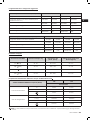
6. Requirements for the total weight of lled
refrigerant and the area of a room to be equipped
with an air conditioner (are shown as in the
following Tables GG.1 and GG.2)
m1= (4m3) x LFL , m2 = (26 m3)) x LFL, m3 = (130m3 )x LFL
Where LFL is the lower ammable limit in kg/ m
3
,R32
LFL is 0.038 kg/ m
3
.
For the appliances with a charge amount m
1
< M = m
2
The maximum charge in a room shall be in accordance
with the following:
m
max
= 2.5 x (LFL)
(5/4)
x h
0
x (A)
1/2
The required minimum oor area Amin to install an
appliance with refrigerant charge M (kg) shall be in
accordance with following:
A
min
= (M/ (2.5 x (LFL)
(5/4)
x h
0
))
2
LFL
)
(m) Floor area (m)
17 15
1.51 1.8
1.8 5.61
5.6 6.86 8.85
LFL
)
(m)
Minimum room area (m
)
51 116
1 116
1.8 6
15
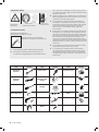
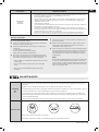
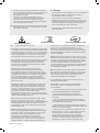
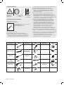
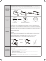
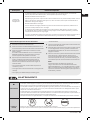
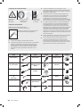
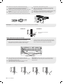
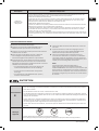
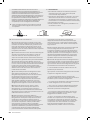
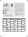
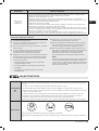
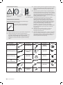
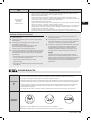
1. Installation Safety Principles
Open Flames Prohibited Ventilation Necessary

18 ACD-24KBTU
Mind Static
Electricity
Must wear
protective clothing
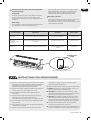
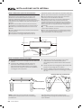
Refrigerant Leak Detector
Appropriate Installation Location
The left picture is the schematic
diagram of a refrigerant leak detector.
Please note that:
1. The installation site should be well-ventilated.
The sites for installing and maintaining an air
conditioner using Refrigerant R32 should be free
from open re or welding, smoking, drying oven or
any other heat source higher than 548 which easily
produces open re.
When installing an air conditioner, it is necessary to
take appropriate anti-static measures such as wear
anti-static clothing and/or gloves.
It is necessary to choose the site convenient for
installation or maintenance wherein the air inlets
and outlets of the indoor and outdoor units should
be not surrounded by obstacles or close to any
heat source or combustible and/or explosive
environment.
5. If the indoor unit suffers refrigerant leak during the
installation, it is necessary to immediately turn off
the valve of the outdoor unit and all the personnel
should go out until the refrigerant leaks completely
for 15 minutes. If the product is damaged, it is a
must to carry such damaged product back to the
maintenance station and it is prohibited to weld the
refrigerant pipe or conduct other operations on the
user's site.
6. It is necessary to choose the place where the inlet
and outlet air of the indoor unit is even.
7. It is necessary to avoid the places where there
are other electrical products, power switch plugs
and sockets, kitchen cabinet, bed, sofa and other
valuables right under the lines on two sides of the
indoor unit.
Don`t use
mobile phone
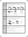
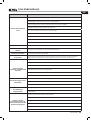
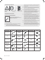
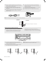
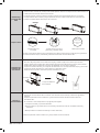
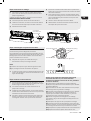
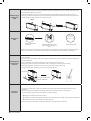
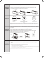
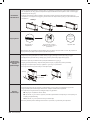
Tool Picture Tool Picture Tool Picture
Standard
Pipe Cutter
Crescent
Screw drivers
blade)
Manifold and
Level
Scale
Clamp on Amp
Meter

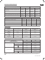
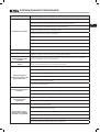
ACD-24KBTU
EN
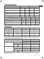
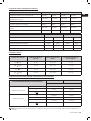
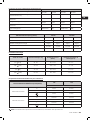
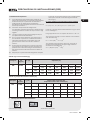
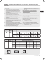
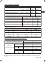
Length of pipe with standard charge 5m/16ft 5m/16ft 5m/16ft 5m/16ft
Length of pipe with standard charge (Like: North
American, etc.) 7.5m/24ft 7.5m/24ft 7.5m/24ft 7.5m/24f t
Maximum distance between indoor and outdoor
unit 15m/49ft 15m/49ft 25m/82ft 25m/82ft
Additional refrigerant charge 20g/m 15g/m 30g/m 25g/m
Max. diff. in level between indoor and outdoor unit 10m/32ft 10m/32ft 10m/32ft 10m/32ft
Type of refrigerant R22/R410A R32 R22/R410A R32
Length of pipe with standard charge 5m/16ft 5m/16ft 5m/16ft 5m/16ft
Maximum distance between indoor and outdoor unit 15m/49ft 15m/49ft 15m/49ft 15m/49ft
Additional refrigerant charge 20g/m 15g/m 30g/m 25g/m
Max. diff. in level between indoor and outdoor unit 5m/16ft 5m/16ft 5m/16ft 5m/16ft
Type of refrigerant R22/R410A R32 R22/R410A R32
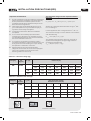
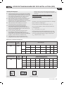
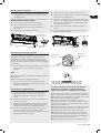
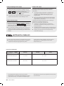
PIPE Size Pound-force foot
(Ibf-ft)
1/4'' ( 6.35) 18 - 20 24.4 - 27.1 2.4 - 2.7
3/8 ''( 9.52) 30 - 35 40.6 - 47.4 4.1 - 4.8
1/2'' ( 12) 45 - 50 61.0 - 67.7 6.2 - 6.9
5/8 ''( 15.88) 60 - 65 81.3 - 88.1 8.2 - 8.9
Dedicated Distribution Device and Wire for Air Conditioner
Note: This table is only for reference, the installation shall meet the requirements of local laws and regulations.
18k
sectional area
Power supply cable
N1.5mm
2
2.5mm
2
L1.5mm
2
2.5mm
2
1.5mm
2
2.5mm
2
Connection cable
N0.75mm
2
0.75mm
2
L or (L) 0.75mm
2
0.75mm
2
10.75mm
2
0.75mm
2
0.75mm
2
0.75mm
2

ACD-24KBTU
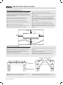
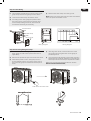
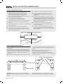
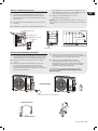
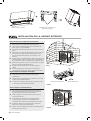
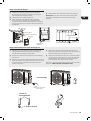
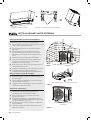
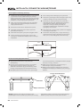
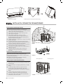
Step 1: Select Installation location
1) Ensure the installation complies with the installation
minimum dimensions (dened below) and meets the
minimum and maximum connecting piping length and
maximum change in elevation as dened in the System
Requirements section.
Air inlet and outlet will be clear of obstructions,
ensuring proper airow throughout the room.
Condensate can be easily and safely drained.
All connections can be easily made to outdoor unit.
5) Indoor unit is out of reach of children.
6) A mounting wall strong enough to withstand four
times the full weight and vibration of the unit.
7) Filter can be easily accessed for cleaning.
8) Leave enough free space to allow access for routine
maintenance.
Install at least 10 ft. (3 m) away from the antenna of
TV set or radio. Operation of the air conditioner may
interfere with radio or TV reception in areas where
reception is weak. An amplier may be required for the
affected device.
Do not install in a laundry room or by a
swimming pool due to the corrosive environment.
11) For ETL certication area, Caution: Mount with the
lowest moving parts at least 8 ft. (2.4 m) above oor or
grade level.
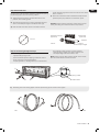
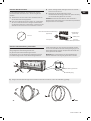
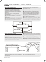
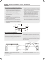
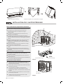
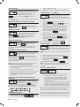
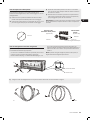
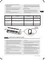
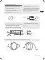
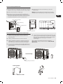
1) Take the mounting plate from the back of indoor unit.
Ensure to meet the minimum installation dimension
requirements as step 1, according to the size of
mounting plate, determine the position and stick the
mounting plate close to the wall.
Adjust the mounting plate to a horizontal state with
a spirit level, then mark out the screw hole positions on
the wall.
Put down the mounting plate and drill holes in the
marked positions with drill.
5) Insert expansion rubber plugs into the holes, then
hang the mounting plate and x it with screws.
Note: (I) Make sure the mounting plate is rm enough
and at against the wall after installation.
(II)This gure shown may be different from the actual
object, please take the latter as the standard.
Ceiling
Floor
>250cm / 8ft.
>20cm / 8 in.
>13cm / 5 in.
>13cm / 5 in.
Reference screw positions
Spirit level
La page est en cours de chargement...
La page est en cours de chargement...
La page est en cours de chargement...
La page est en cours de chargement...
La page est en cours de chargement...
La page est en cours de chargement...
La page est en cours de chargement...
La page est en cours de chargement...
La page est en cours de chargement...
La page est en cours de chargement...
La page est en cours de chargement...
La page est en cours de chargement...
La page est en cours de chargement...
La page est en cours de chargement...
La page est en cours de chargement...
La page est en cours de chargement...
La page est en cours de chargement...
La page est en cours de chargement...
La page est en cours de chargement...
La page est en cours de chargement...
La page est en cours de chargement...
La page est en cours de chargement...
La page est en cours de chargement...
La page est en cours de chargement...
La page est en cours de chargement...
La page est en cours de chargement...
La page est en cours de chargement...
La page est en cours de chargement...
La page est en cours de chargement...
La page est en cours de chargement...
La page est en cours de chargement...
La page est en cours de chargement...
La page est en cours de chargement...
La page est en cours de chargement...
La page est en cours de chargement...
La page est en cours de chargement...
La page est en cours de chargement...
La page est en cours de chargement...
La page est en cours de chargement...
La page est en cours de chargement...
La page est en cours de chargement...
La page est en cours de chargement...
La page est en cours de chargement...
La page est en cours de chargement...
La page est en cours de chargement...
La page est en cours de chargement...
La page est en cours de chargement...
La page est en cours de chargement...
La page est en cours de chargement...
La page est en cours de chargement...
La page est en cours de chargement...
La page est en cours de chargement...
La page est en cours de chargement...
La page est en cours de chargement...
La page est en cours de chargement...
La page est en cours de chargement...
La page est en cours de chargement...
La page est en cours de chargement...
La page est en cours de chargement...
La page est en cours de chargement...
La page est en cours de chargement...
La page est en cours de chargement...
La page est en cours de chargement...
La page est en cours de chargement...
La page est en cours de chargement...
La page est en cours de chargement...
La page est en cours de chargement...
La page est en cours de chargement...
La page est en cours de chargement...
La page est en cours de chargement...
La page est en cours de chargement...
La page est en cours de chargement...
La page est en cours de chargement...
La page est en cours de chargement...
La page est en cours de chargement...
La page est en cours de chargement...
La page est en cours de chargement...
La page est en cours de chargement...
La page est en cours de chargement...
La page est en cours de chargement...
La page est en cours de chargement...
La page est en cours de chargement...
La page est en cours de chargement...
La page est en cours de chargement...
La page est en cours de chargement...
La page est en cours de chargement...
La page est en cours de chargement...
La page est en cours de chargement...
La page est en cours de chargement...
La page est en cours de chargement...
La page est en cours de chargement...
La page est en cours de chargement...
La page est en cours de chargement...
La page est en cours de chargement...
La page est en cours de chargement...
La page est en cours de chargement...
La page est en cours de chargement...
La page est en cours de chargement...
La page est en cours de chargement...
La page est en cours de chargement...
La page est en cours de chargement...
La page est en cours de chargement...
La page est en cours de chargement...
La page est en cours de chargement...
La page est en cours de chargement...
La page est en cours de chargement...
La page est en cours de chargement...
La page est en cours de chargement...
La page est en cours de chargement...
La page est en cours de chargement...
La page est en cours de chargement...
La page est en cours de chargement...
La page est en cours de chargement...
La page est en cours de chargement...
La page est en cours de chargement...
La page est en cours de chargement...
La page est en cours de chargement...
La page est en cours de chargement...
La page est en cours de chargement...
La page est en cours de chargement...
La page est en cours de chargement...
La page est en cours de chargement...
La page est en cours de chargement...
La page est en cours de chargement...
La page est en cours de chargement...
La page est en cours de chargement...
La page est en cours de chargement...
La page est en cours de chargement...
La page est en cours de chargement...
La page est en cours de chargement...
La page est en cours de chargement...
La page est en cours de chargement...
La page est en cours de chargement...
La page est en cours de chargement...
La page est en cours de chargement...
La page est en cours de chargement...
La page est en cours de chargement...
La page est en cours de chargement...
La page est en cours de chargement...
La page est en cours de chargement...
La page est en cours de chargement...
La page est en cours de chargement...
La page est en cours de chargement...
La page est en cours de chargement...
La page est en cours de chargement...
La page est en cours de chargement...
La page est en cours de chargement...
La page est en cours de chargement...
La page est en cours de chargement...
La page est en cours de chargement...
La page est en cours de chargement...
La page est en cours de chargement...
La page est en cours de chargement...
La page est en cours de chargement...
La page est en cours de chargement...
La page est en cours de chargement...
La page est en cours de chargement...
La page est en cours de chargement...
La page est en cours de chargement...
La page est en cours de chargement...
La page est en cours de chargement...
La page est en cours de chargement...
-
 1
1
-
 2
2
-
 3
3
-
 4
4
-
 5
5
-
 6
6
-
 7
7
-
 8
8
-
 9
9
-
 10
10
-
 11
11
-
 12
12
-
 13
13
-
 14
14
-
 15
15
-
 16
16
-
 17
17
-
 18
18
-
 19
19
-
 20
20
-
 21
21
-
 22
22
-
 23
23
-
 24
24
-
 25
25
-
 26
26
-
 27
27
-
 28
28
-
 29
29
-
 30
30
-
 31
31
-
 32
32
-
 33
33
-
 34
34
-
 35
35
-
 36
36
-
 37
37
-
 38
38
-
 39
39
-
 40
40
-
 41
41
-
 42
42
-
 43
43
-
 44
44
-
 45
45
-
 46
46
-
 47
47
-
 48
48
-
 49
49
-
 50
50
-
 51
51
-
 52
52
-
 53
53
-
 54
54
-
 55
55
-
 56
56
-
 57
57
-
 58
58
-
 59
59
-
 60
60
-
 61
61
-
 62
62
-
 63
63
-
 64
64
-
 65
65
-
 66
66
-
 67
67
-
 68
68
-
 69
69
-
 70
70
-
 71
71
-
 72
72
-
 73
73
-
 74
74
-
 75
75
-
 76
76
-
 77
77
-
 78
78
-
 79
79
-
 80
80
-
 81
81
-
 82
82
-
 83
83
-
 84
84
-
 85
85
-
 86
86
-
 87
87
-
 88
88
-
 89
89
-
 90
90
-
 91
91
-
 92
92
-
 93
93
-
 94
94
-
 95
95
-
 96
96
-
 97
97
-
 98
98
-
 99
99
-
 100
100
-
 101
101
-
 102
102
-
 103
103
-
 104
104
-
 105
105
-
 106
106
-
 107
107
-
 108
108
-
 109
109
-
 110
110
-
 111
111
-
 112
112
-
 113
113
-
 114
114
-
 115
115
-
 116
116
-
 117
117
-
 118
118
-
 119
119
-
 120
120
-
 121
121
-
 122
122
-
 123
123
-
 124
124
-
 125
125
-
 126
126
-
 127
127
-
 128
128
-
 129
129
-
 130
130
-
 131
131
-
 132
132
-
 133
133
-
 134
134
-
 135
135
-
 136
136
-
 137
137
-
 138
138
-
 139
139
-
 140
140
-
 141
141
-
 142
142
-
 143
143
-
 144
144
-
 145
145
-
 146
146
-
 147
147
-
 148
148
-
 149
149
-
 150
150
-
 151
151
-
 152
152
-
 153
153
-
 154
154
-
 155
155
-
 156
156
-
 157
157
-
 158
158
-
 159
159
-
 160
160
-
 161
161
-
 162
162
-
 163
163
-
 164
164
-
 165
165
-
 166
166
-
 167
167
-
 168
168
-
 169
169
-
 170
170
-
 171
171
-
 172
172
-
 173
173
-
 174
174
-
 175
175
-
 176
176
-
 177
177
-
 178
178
-
 179
179
-
 180
180
-
 181
181
-
 182
182


Aiwa ACD-24KBTU Manuel utilisateur
- Catégorie
- Climatiseurs split-system
- Taper
- Manuel utilisateur
dans d''autres langues
- italiano: Aiwa ACD-24KBTU Manuale utente
- español: Aiwa ACD-24KBTU Manual de usuario
- Deutsch: Aiwa ACD-24KBTU Benutzerhandbuch
- polski: Aiwa ACD-24KBTU Instrukcja obsługi
Documents connexes
Autres documents
-
EAS ELECTRIC MAJESTIC25K Manuel utilisateur
-
TCL W5P93 BTU Smart Portable Air Conditioner Manuel utilisateur
-
TCL MZ Mode d'emploi
-
White-Westinghouse WS18K57DCHI Le manuel du propriétaire
-
 Kaysun Individual Wireless controller KID-06 S Manuel utilisateur
-
mundoclima MUEX-H9 “MultiSplit System” Guide d'installation
-
-
Tosot TPAC12S-H116A3 Manuel utilisateur
-
Airwell RC08C Manuel utilisateur
-
DeLonghi PLS120 Le manuel du propriétaire
