
1
Model GX-SEKONIC-A
Users Manual
批准 检证 负责人
Godox stamped
Wireless module/GX-SEKONIC-A

2
Table of Contents
Chapter 1 Overview .......................................................................................................................................................................... 3
1.1 Scope of application ................................................................................................................................................................ 3
1.2 Product overview .................................................................................................................................................................... 3
Chapter 2 Appearance and structure ................................................................................................................................................. 5
2.1 Appearance and dimensions ....................................................................................................................................................... 5
Chapter 3 Electrical Specifications ................................................................................................................................................... 6
3.1 Host connection interface ....................................................................................................................................................... 6
Chapter 4 Wireless Specifications .................................................................................................................................................... 8
4.1 Physical specifications ............................................................................................................................................................ 8
4.2 Protocol specifications ............................................................................................................................................................ 8
Chapter 5 Internal Control ................................................................................................................................................................ 9
Chapter 6 Embedded Specifications ............................................................................................................................................... 10
6.1 Mechanical conditions .............................................................................................................................................................. 10
6.2 Electrical conditions .............................................................................................................................................................. 11
Chapter 7 Radio Compliance .......................................................................................................................................................... 12
7.1 Europe ................................................................................................................................................................................... 12
7.2 United States and Canada ..................................................................................................................................................... 13

3
Chapter 1 Overview
1.1 Scope of application
This specification describes the operation and handling of the following products.
Customer name: SEKONIC CORPORATION
Product name: Transmitted radio wave module model GX-SEKONIC-A
Product code: GX
Related Regulations: Radio Law, Specified Low Power Radio Equipment ARIB-T66
FCC 47CFR Part15.C, Canada RSS Gen/RSS 210
EU RE Directive 2014/53/EU, ETSI EN 300 440,
EN62479
Environmental protection: Lead-free solder compatible
SEKONIC SKGP
1.2 Product overview
"Transmission radio wave module" is a board module product for the wireless transmission function that uses the
2.4 GHz ISM band.
This product is designed for remote control of professional lighting for photography by incorporating it into
products such as Sekonic's light meter/color meter.
The "Transmission Radio Module" (Model GX) is compatible with the Godox X series 2.4G receiver system as a
compatible radio system.
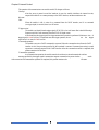
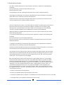
The internal function of the "transmit radio wave module" (Model GX) consists of a 8-bit microcomputer made by
TI, a transmission amplifier with +20dBm output, and the antenna is a pattern antenna on the circuit
board.
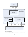
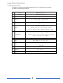
The following figure shows the outline of the internal configuration of this product and the connection with the
embedded host

4
Above: Connect to the parent device with the 12-pin connector on the left side, and operate with the power
supply (DC3V) from the parent device.
The main connection signals are the trigger switch signal (SyncIn) and UART serial communication (3V).
Exposure Meter microcomputer
CC2592
PA-ENLNA-EN
Port Control
CC2510
Wireless module MCU
with RF Function
Interrupt
USART Control
RF Control
RxDTxD READY CLEARTOSENDSYNC_IN# RESET

5
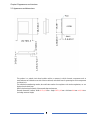
Chapter 2 Appearance and structure
2.1 Appearance and dimensions
This product is a printed circuit board module and has a structure in which electronic components such as
semiconductors are soldered on one side of the circuit board, and a shield case for protecting the circuit components
is soldered on it.
The individual manufacturing number, the certification number for compliance with wireless regulations, etc. are
displayed on the shield case.
Refer to the drawings for details of the external shape and structure.
External dimensions (outline) Width 24.70±0.3mm x length 28.70±0.3mm x thickness 8.44mm +0.9/-0.6mm
(including connector height)

6
Chapter 3 Electrical Specifications
3.1 Host connection interface
This product is connected to the embedded master device with a 2.0 mm pitch/12-pin connector.
The signals to be connected are as follows.
Pin function Signal reliability
1 +3.3VDC Power supply +3.3V
2 (SYNC_OUT) None (Fixed ”1”)
3 SYNC_IN Input hardware triggering
0 : Triggering ON (over 100 usec)
1 : Triggering OFF
4 TX_Complete None
5 READY Status for trigger
0 ; Unable to receive trigger (Sending trigger)
1 : Able to receive trigger (Completed sending trigger)
6 CLEARTOSEND Status for receiving serial command
0 : Unable to receive serial command (Processing command)
1 :Able to receive serial command
7 TXD UART(ASYNC serial) Output data
8 RXD UART (ASYNC serial) Input data
9 RESET Reset module
0 : Reset ON (Over 1000 usec)
1 : Reset OFF
10 GND Ground
11 ANTTENA For jig test
12 GND Ground

7
The connector on this product is 200-FH-1-12-43-S-28-24-GO-A (socket), and the square pin type header pin
(product example: IK210SM-S12G-T15) is suitable as the parent device side connector.
・Power supply (1 pin)
Input power supply voltage DC3.0V~3.6V, current consumption 0.09A maximum
・Trigger signal (3-pin)
Active low (minimum 100uS width) transmission request signal.
It sends a “TRIGGER” signal based on the preselected radio system specifications.
・Internal operation status signal (4,5)
This is a 3V-CMOS logic signal that indicates the operating status of wireless transmission.
TX_COMPLETE/READY becomes Low when the trigger signal is recognized, and becomes High
when the transmission operation is completed.
・UART interface (7,8 pin)
3V CMOS level UART interface signal. It can be directly connected to the MPU of the parent device.
Serial communication parameters Communication speed 38400bps, 8bit, No parity, Stop 1 bit
Do not connect RS232 level signals as this will damage the internal circuitry.
Use a level converter circuit when connecting a personal computer, etc.
・Reset signal (9 pin)
This is an active low hardware reset signal (minimum 1000uS width) that resets the internal
operation of the transmitting radio wave module from the parent device.
・ANTTENA signal (11 pin)
Active low Testing enable signal.

8
Chapter 4 Wireless Specifications
4.1 Physical specifications
Item Minimum Typical Maximum unit
Transmission frequency
range 2412.999634 2464.499756
MHz
Transmission channel Step 1.2 1.5 MHz
Frequency stability -50 +10 kHz
Transmit output power -0.5 +4.0 dBm
Antenna gain 0 dBi
4.2 Protocol specifications
This product has a mode compatible with two communication procedures of the system as the operation of wireless
transmission. The wireless transmission operation in these two modes is based on the CC2510Fx protocol of TI,
but the detailed definitions have their respective characteristics and are not compatible.
For example, the following parts are different
Channel number and physical frequency assignment
Concept of physical/logical channel and group control
Transmission data rate and data packet structure
The definition outline of each radio interface is as follows.
Characteristic items Godox Mode Unit
Modulation method MSK
Frequency channel definition Channel
Number Frequency
(GHz) Channel
Number Frequency
(GHz)
1 2.412999634 17 2.439499908
2 2.414499664 18 2.441749756
3 2.415999695 19 2.442999847
4 2.418000000 20 2.444499878
5 2.419499634 21 2.446749725
6 2.420999664 22 2.447999817
7 2.422999969 23 2.449499847
8 2.424500000 24 2.451749695
9 2.426749847 25 2.452999786
10 2.427999939 26 2.454499817
11 2.429499969 27 2.456749664
12 2.431749816 28 2.457999756
13 2.432999908 29 2.459499786
14 2.434499939 30 2.461749634
15 2.436249908 31 2.462999725
16 2.437999878 32 2.464499756
GHz
Transmission data rate 250 Kbps
Group control 16 groups + ALL
(Group settings are independent of each other,
combination specification is not possible
The default settings of the transmitting radio wave module at the first startup are as follows.
Godox mode、CH 1
Please refer to the firmware specifications for detailed operation and control.
Firmware Design Specification

9
Chapter 5 Internal Control
The operation of the transmission wave module model GX changes as follows.
"Start-up"
After the power is turned on and the hardware is reset, the module initializes the internal circuits,
outputs the module ID as a startup message to the UART interface, and then transitions to the
idle state.
"Idle"
When the module is idle, it waits for a command from the UART interface, and if no command
(or trigger signal) is received, there is no RF action.
"Trigger action"
The module can identify that the trigger signal (SYNC-IN) is low in all states. But it should following a
Prepare main flash Usart command, then the SYNC-IN signal comes.
After identifying the trigger signal, the trigger transmission operation is performed. (Minimum time of
trigger signal is 100uS or more) To implement one-shot trigger operation, do not set the trigger
signal to the Low state for 50mS or more.
"Command operation"
The module can receive UART commands in any state, When the command received from the UART
interface is valid, the processing specified by the command is executed. Command processing is a send
operation or a message response to the UART interface. After the command execution is completed, this
product transits to the idle state.
"Transmission operation"
As a transmission operation, the module controls the wireless circuit and transmits the wireless
message specified by the trigger signal or transmission request command in the preset wireless mode.
After execution of the transmission operation is completed, this product transits to the idle state.

10
Chapter 6 Embedded Specifications
The transmission radio wave module model GX is designed to be used by incorporating it into the Seconic
L-858-D exposure meter. It can be incorporated into other equipment, but it must meet the following
conditions.
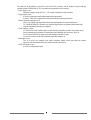
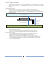
6.1 Mechanical conditions
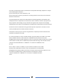
As shown in the figure below, the mechanical conditions for installing the module are as follows:
(CON) must be mechanically adapted. In addition, the space in which the board is installed does not allow
the wireless performance of the antenna installed in the module to be demonstrated simply by providing the
minimum board space.
Concept of required space (clearance)
Do not use metal or resin with an electrostatic shielding property for the casing (casing) of the
parent device to be incorporated. If the module part is covered with metal parts, radio waves
cannot be emitted to the outside.
In order to maximize the wireless performance (communication distance performance) of the
antenna, make sure that there is no object around the antenna part of the module.
Furthermore, even if a resin housing is used, the characteristics will deteriorate if the antenna
part of the module and the case are close to each other. To avoid this, make sure there is a gap of at least
3 mm between the back side of the module (the side without the component/shield case) and the resin
case of the embedded parent device.
Host equipment Casing
Module Board < 1.63mm thick >
Host Board (PCB)
[Module height]
8.44mm
Shield < 2.54mm height >
Header height
1.5mm
Topside –Clearance > 3 mm
Board Clearance ≒5.8 mm

11
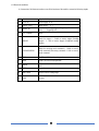
6.2 Electrical conditions
(1) Connection of all functions in order to use all the functions of the module, connect the following signals.
Pin function Signal reliability
1 +3.3VDC Power supply +3.3V
2 (SYNC_OUT) None (Fixed ”1”)
3 SYNC_IN Input hardware triggering 0 : Triggering ON (over 100
usec) 1 : Triggering OFF
4 TX_Complete None
5 READY Status for trigger 0 ; Unable to receive trigger (Sending
trigger) 1 : Able to receive trigger (Completed sending
trigger)
6 CLEARTOSEND Status for receiving serial command 0 : Unable to receive
serial command (Processing command) 1 :Able to receive
serial command
7 TXD UART(ASYNC serial) Output data
8 RXD UART (ASYNC serial) Input data
9 RESET Reset module 0 : Reset ON (Over 1000 usec) 1 : Reset
OFF
10 GND Ground
11 ANTTENA Active Low for Testing usage
12 GND Ground

12
Chapter 7 Radio Compliance
The transmission radio wave module model GX uses radio waves in the 2.4 GHz band and can be used in most
countries and regions of the world without obtaining permission to use it wirelessly. It is necessary to comply with the
relevant regulations.
The transmission wave module model GX complies with the following laws and regulations.
7.1 Europe
The radio wave module model EP has been tested and manufactured based on the technical standards for
embedded wireless modules specified by the European Commission's Radio and Communication
Terminals Directive (RE Directive ), and bears the CE mark.
This product has been tested to the following basic radio and communication device directive (RE
Directive) 2014/53/EU radio wave equipment and health/safety requirements.
Wireless
equipment aticle 3(2) EN300 440 v2.2.1
Human body electromagnetic field exposure aticle 3(1)a EN62479
The manufacturer of the product incorporating this product shall retain the technical data of this product, ensure
that the wireless standard values and antenna performance do not deviate from the module specifications in the final
product state, and meet the requirements for installation. It is necessary to check. Please contact your sales representative
to obtain the test report.
Regarding EU directives for electronic devices other than wireless devices, it is necessary to confirm that they are
satisfied as final products. (Electromagnetic environment compatibility, low voltage directive, environmental directive, etc.)
Equipment incorporating this product must display the "CE mark" on the visible part of the product.
At that time, the following points are required.
・The CE mark can be reduced/enlarged, but the proportion must be in accordance with the regulations.
・The CE mark requires a minimum height of 5 mm.
・The CE mark is easy to see and should not disappear or come off.
For more information on CE marking requirements, please refer to Article 19 of the Radio &
Telecommunications Terminal Directive (RE Directive, 2014/53/EU).
Properly CE marked products can be sold and used within the EU and do not require local certification testing
in EU countries.

13
7.2 United States and Canada
This device complies with part 15 of the FCC Rules. Operation is subject to the following two
conditions:
(1) This device may not cause harmful interference, and
(2) this device must accept
any interference received, including interference that may cause undesired operation.
Any Changes or modifications not expressly approved by the party responsible for compliance
could void the user's authority to operate the equipment.
The device has been evaluated to meet general RF exposure requirement. The device can be
used in portable exposure condition without restriction.
If the FCC identification number is not visible when the module is installed inside another device,
then the outside of the device into which the module is installed must also display a label
referring to the enclosed module. This exterior label can use wording such as the following:
“Contains Transmitter Module FCC ID: 2ABYN-GX Or Contains FCC ID: 2ABYN-GX”
When the module is installed inside another device, the user manual of the host must contain
below warning statements;
1. This device complies with Part 15 of the FCC Rules. Operation is subject to the following two
conditions:
(1) This device may not cause harmful interference.
(2) This device must accept any interference received, including interference that may cause
undesired operation.
2. Changes or modifications not expressly approved by the party responsible for compliance
could void the user's authority to operate the equipment.
The devices must be installed and used in strict accordance with the manufacturer's instructions
as described in the user documentation that comes with the product.
Any company of the host device which install this modular with Single modular approval should
perform the test of radiated emissionand spurious emission according to FCC part 15C : 15.247
and 15.209 requirement,Only if the test result comply with FCC part 15C : 15.247 and 15.209
requirement,then the host can be sold legally.
Note: This equipment has been tested and found to comply with the limits for a Class B digital
device, pursuant to part 15 of the FCC Rules. These limits are designed to provide reasonable
protection against harmful interference in a residential installation. This equipment generates,
uses and can radiate radio frequency energy and, if not installed and used in accordance with the
instructions, may cause harmful interference to radio communications. However, there is no
guarantee that interference will not occur in a particular installation. If this equipment does
cause harmful interference to radio or television reception, which can be determined by turning
the equipment off and on, the user is encouraged to try to correct the interference by one or more
of the following measures:
—Reorient or relocate the receiving antenna.
—Increase the separation between the equipment and receiver.
—Connect the equipment into an outlet on a circuit different from that to which the receiver is connected.
—Consult the dealer or an experienced radio/TV technician for help.

14
This device complies with Industry Canada licence-exempt RSS standard(s). Operation is subject
to the following two conditions:
(1) This device may not cause interference, and
(2) This device must accept any interference, including interference that may cause undesired
operation of the device.
Le présent appareil est conforme aux CNR d'Industrie Canada applicables aux appareils radio
exempts de licence. L'exploitation est autorisée aux deux conditions suivantes: (1) l'appareil ne
doit pas produire de brouillage, et (2) l'utilisateur de l'appareil doit accepter tout brouillage
radioélectrique subi, même si le brouillage est susceptible d'en compromettre le fonctionnement
The device has been evaluated to meet general RF exposure requirement. The device can be
used in portable exposure condition without restriction.
Le dispositif a été conçu pour rencontrer le général RF. Le dispositif peut être utilisé dans des
conditions de détention sans effet.
For a host manufacture's using a certified modular, if (1) the module's IC number is not visible
when installed in the host, or (2) if the host is marketed so that end users do not have
straightforward commonly used methods for access to remove the module so that the IC number
of the module is visible; then an additional permanent label referring to the enclosed module:
"Contains Transmitter Module IC: " 20034-GX " or "Contains IC: 20034-GX" must
be used.
Pour un hôte, on utilise un modular, si (1) le numéro de module est non visible
Quand on est installé dans le serveur, or (2) si le propriétaire est commercialisé
Straightforward commonly used for the access to remove travail so that the number IC en vue
Le module est visible;Ensuite, le label permanent a été attribué au module:
"Contient le Module IC:" 20034-GX" ou "le contenu IC: 20034-GX" doit être
utilisé.

15
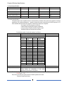
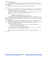
Revision history
Revision Page Description/Changes Responsible
0.1 All Godox information ZouQiang
0.2 6 External dimensions ZouQiang
0.2 9 Channel Frequency and Group control ZouQiang
-
 1
1
-
 2
2
-
 3
3
-
 4
4
-
 5
5
-
 6
6
-
 7
7
-
 8
8
-
 9
9
-
 10
10
-
 11
11
-
 12
12
-
 13
13
-
 14
14
-
 15
15


Godox GX-SEKONIC-A Wireless Module Manuel utilisateur
- Taper
- Manuel utilisateur
- Ce manuel convient également à
dans d''autres langues
Autres documents
-
Continental HFM201 Manuel utilisateur
-
 FEUYMOENT LET614 Manuel utilisateur
-
Multitech MTQ-H5-B01 Mode d'emploi
-
Multitech MTXDOT-NA1-A00-100 Mode d'emploi
-
Multitech MultiConnect xDot MTXDOT-NA1-A00 Developer's Manual
-
-
-
Multitech MTQ-MNA1-B01-SP Mode d'emploi
-
Multi-Tech MultiConnect Dragonfly Nano MTQN-MNG1-B02 Device Manual
-
