
Net2 Plus and Power supplies
ins-20606
Paxton

1
2
4
3
1
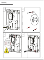
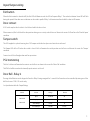
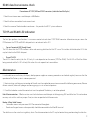
Mounting

1 2
Note: This mounting process applies to all types of cabinet and housing regardless of size, material or power supply included.
1. Screws and wall plugs are provided in a parts kit. With reference to the diagram, mark up the hole positions as required and drill the holes
suitable for No 8 wall plugs.
2. Tap in all three wall plugs and insert a long screw into the top, central mounting hole, leaving a suitable gap to the wall surface in order to slot
the cabinet over it.
3. Hang the cabinet over the inserted screw as directed and tighten until secure. If the cabinet is not suciently secure, be wary of the unit falling.
4. Secure the cabinet with the two lower screws.
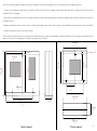
This housing should be xed to the surface with suitable fasteners; screws and wall plugs are provided for this in the tting kit. Also provided are
cable ties to secure the cabling and a smaller securing screw for the lid.
318 mm
318 mm
12.5“
7.8“
3.18 “
10.5 “
1 “
12.5”
200mm
159 mm
25 mm
81 mm
6.4 “
162 mm
3.9 “
6.2“
100 mm
268 mm
0.6 “15 mm
6.6 “
167 mm
200 mm
7.9”
200 mm
7.9”
200 mm
7.9”
69
2.71”
74 mm
2.9”
Metal cabinet Plastic cabinet

3
0V
Net2 plus
0V
0V
0V
0V
0V
PSU
OK
0V
0V
ARM
SENSE
N.C.
N.O
1
2
COM
N.C.
N.O
COM
Data/D0
Clock/D1
CAT5
RS485
Media
Detect
0V
10
TX RX
100
Data/D0
Clock/D1
Media
Detect
10/100 Ethernet
N.C.
N.O
COM
12V - 24V
12V
1
2
12V
LED
LED
LED
12V
LED
LED
LED
LED
EXIT
EXIT
PSU
12V DC
12V DC
I
TX RX
TX RX
TX RX
TX RX
0V
Net2 plus
0V
0V
0V
0V
0V
PSU
OK
0V
0V
ARM
SENSE
N.C.
N.O
1
2
COM
N.C.
N.O
COM
Data/D0
Clock/D1
CAT5
RS485
Media
Detect
0V
10
TX RX
100
Data/D0
Clock/D1
Media
Detect
10/100 Ethernet
N.C.
N.O
COM
12V - 24V
12V
1
2
12V
LED
LED
LED
12V
LED
LED
LED
LED
EXIT
EXIT
PSU
12V DC
12V DC
I
TX RX
TX RX
TX RX
TX RX
V21
V0
V21
V0
V42
V0
USP
V0
0V
0V
N.C.
N.O
COM
N.C.
N.O
COM
Data/D0
Clock/D1
0V
Data/D0
Clock/D1
12V
1
2
12V
LED
LED
LED
LED
LED
LED
12V DC
Paxton
0V
0V
N.C.
N.O
COM
N.C.
N.O
COM
Data/D0
Clock/D1
0V
Data/D0
Clock/D1
12V
1
2
12V
LED
LED
LED
LED
LED
LED
12V DC
Paxton
0V
0V
0V
0V
N.C.
N.O
2
COM
N.C.
N.O
COM
Data/D0
Clock/D1
CAT5
RS485
0V
10
TX RX
100
Data/D0
Clock/D1
10/100 Ethernet
N.C.
N.O
COM
12V - 24V
12V
1
2
12V
LED
LED
LED
12V
LED
LED
LED
LED
EXIT
12V DC
12V DC
I
1
Paxton
Net2 plus
12V - 24V
10/100 Ethernet
RS485
CAT5
TX RX
TX RX
TX RX
TX RX
Net2 plus
TX RX
RS485
CAT5
TX RX
TX RX
12V
N.C.
COM
0V
LED
EXIT
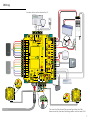
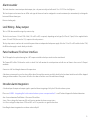
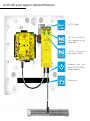
Wiring
Intruder alarm not evaluated by UL
The use of a Fail closed/Secure conguration shall be
determined by the local building codes and the local AHJ.

3 4
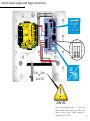
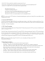
LED indications
Overview
• 12/24V (Green) Power LED.
• Relay 1 (Orange) The relay is energised - (NO/COM contacts are closed).
• Relay 2 (Orange) The relay is energised - (NO/COM contacts are closed).
• Alarm (Red) 12V Alarm output is active.
• Exit (Orange) The exit button contacts are closed.
• Contact (Orange) The door contacts are closed.
• Tamper (Orange) The tamper contacts are closed.
• PSU (Orange) The PSU contacts are closed.
• OK (Green ash) The internal software is running.
• Termination (Red) The on-board resistors are in place across the RS485 data pairs.
• Rx (Red) The ACU is receiving data (TCP/IP or RS485) - See also FAQ section.
• Tx (Green) The ACU is responding to data - (TCP/IP or RS485).
• Server Connected (Green) The TCP/IP interface is communicating with the PC Net2 server.
• Server Link - Green = 100 Mbit/s : Orange = 10 Mbit/s (TCP/IP speed).
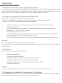
A Net2 plus can connect to the Net2 PC using either an un-shielded RJ45 patch cable or an RS485 data line. This greatly increases the
number of installation options available to the installer.
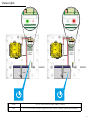
Two typical site layouts are:
1 - The Net2 plus ACU’s can be individually connected to the Net2 PC via the site LAN network.
2 - Using a RS485 ‘daisy chain’ dataline, a Net2 plus ACU can be used as a TCP/IP converter for a line of Net2 plus ACU’s.
When used with an RS485 data line, on-board termination resistors can be put in circuit with a simple slide switch. Ensure that units
installed in the middle of the data line have this switch turned OFF.
The Net2 plus shall be installed within the protected premises as both the power and lock wiring is present at the PCB. A Tamper alarm
input is provided on the PCB - See the Input/Output Wiring section
The Net2 plus’ will continue to operate in a ‘standalone’ mode if the PC is shut down or the dataline is disconnected. Any Events that
occur during this period are stored in the Net2 plus and the PC is updated when it comes back on line.
The PC must be running for any ‘server based’ functions to operate. (Antipassback, Time and Attendance, etc)
To see the installation options available and important information relating to the installation and conguration of the Net2 plus, please
refer to the Application notes section on the website: paxton.info/1969

5
Input/Output wiring
Exit button
When the Exit terminal is shorted to 0V, the Exit LED will illuminate and the ACU will operate Relay 1. The reader/exit button Green LED will ash
during this period. More than one exit button can be wired in parallel. Relay 1 will remain transferred while the short to 0V remains.
Door Bell - Relay 2
Pressing the bell button on the keypad will result in Relay 2 being energized for 1 second. A bell sounder can be controlled by wiring one of the
bell feeds across COM / NO on the relay.
See Specication table for Output Ratings
Door contact
A NO switch may be tted so that it is held closed while the door is shut.
When connected, Net2 will check the door position during access activity and will raise an Alarm in the event of a ‘Door Forced’ or ‘Door left open’
condition.
Tamper switch
The ACU supplied in a plastic housing has a ‘NO’ tamper switch tted and pre-wired into the circuit board.
The Tamper LED will be ON when the switch is closed. Net2 will monitor the switch position and will raise an Alarm in the event of a ‘Tamper’
condition.
Connect to a UL listed burglar alarm unit for supervision.
PSU monitoring
The Net 2 software will monitor the contacts and will raise an alarm in the event of a ‘Mains Fail’ condition.
The PSU Led will be on when the ‘normally open’ contacts are ‘closed’.
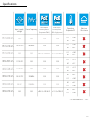
682-528-US
682-493-US
Input 12-24V DC 3A
Relay Output 24V DC 4A
Alarm Output 12V DC 1A
Reader Output 11.5V DC 500mA
CircuitModel Voltage Current

5 6
Alarm sounder
Lock Wiring - Relay output
Panic hardware/ Fire Door Interface
Intruder alarm integration
This local alarm has a transistor ‘open drain’ output, (not a dry contact relay) and will switch 1A at 12V DC for a bell, light etc.
This local output can be turned on or o for each type of alarm and can be congured to sound continuously or intermittently to distinguish
between dierent alarm types.
Resistive loading only
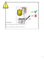
This is a ONE door controller using a dry contact relay
The lock is wired across 12V and COM. A link (12V to NO or NC) is required, depending on lock type (Fail Closed / Open). Fit the supplied diode
across 12V and COM (Silver end to 12V ) to protect the relay contacts.
The dry relay contacts can be used to switch the power from an independent lock power supply. Wire the 12V to NC or NO and the lock to COM;
the 0V from the supply is wired directly to the lock
The ACU supplied in a plastic housing has a ‘NO’ tamper switch tted and pre-wired into the circuit board.
The Tamper LED will be ON when the switch is closed. Net2 will monitor the switch position and will raise an Alarm in the event of a ‘Tamper’
condition.
Connect to a UL listed burglar alarm unit for supervision.
A re alarm system must be used to release all re doors. External relay contacts are held closed by the re alarm’s interface and will be dropped
during an alarm condition. The system is fail safe as the door will release even if the cable burns through.
A dedicated port for input and output signals is provided when integrating a Net2 plus ACU with an alarm system.
Please see: AN1035 - Integrating Net2 with an intruder alarm system www.paxton.info/91 or call Technical Support for further information.
Arm - Arm conrmation Push Button - Wire across 0V and Arm.
Sense - Wire a voltage free loop across 0V and Sense to monitor the alarms current status.
Set - Wire a voltage free loop across COM and N.O. or N.C. to provide a set signal for the alarm
Note: Burglar alarm integration has not been evaluated by UL

7
Cable type
Wiring installation and test
Connecting to the PC or other ACU’s via the RS485 data connection
An RS485 data line has a 1000 yds maximum. This distance can be increased with the use of Paxton high speed repeaters or by using
shorter independent data lines using multiple LAN connections controlled from the same PC.
The RS485 communications port is used for uploading rmware and user information as well as providing Event information to the PC.
Category 5e cabling is the minimum performance category recommended
1. Wire the components to the Net2 Plus Access Control Unit (ACU) as shown on the third page.
2. Press the exit button or in the absence of an exit button short the 0V and exit terminals to test the relay function. The lock Relay LED
will come on and the lock should release.
3. If there are any Readers or keypads wired to the Net2 plus, ensure that all the LED’s are lit on each reader/keypad. Test each reader/
keypad by presenting a token to the unit. It should beep and display a single ashing red or green LED. The reader or keypads default
indication has all the LED’s on. Access granted is denoted with a single ashing Green LED. Access Denied is a single ashing Red LED.
The minimum conductor gauge permitted to connect between the PSE or power injector and the powered device shall be 26 AWG.
This product is for indoor use only and is not intended for outside wiring as covered by article 800 in the National Electrical code,
NFPA 70
Note: Each time the Net2 Plus is powered on, it will run an internal health check. During this phase (about 5 secs) the OK LED will ash
quickly before changing to a slower heartbeat.
90% of installation faults are caused by wiring errors on the RS485 data line.
Special attention to this area can save time and eort.
RS485 data line 1000 yrds 2 x twisted pairs - Belden 8723 or Cat5 equivalent
Input/Output 100 yrds 2 conductor - Alpha 1172C (22AWG) or equivalent
Reader/Keypad 82 feet 8 core, shielded - Belden 9538/ 5506FE (22/24AWG/ 8C)
or General Cable C0744A/ E2008S (22/24AWG/8C)
Reader/Keypad 328 feet
8 core shielded cable - Belden 9540/ 5306FE (24/18 AWG/10C/8C)
or General Cable C0745A/ General Cable C0745A (24/18 AWG/10C/8C)
TypeMax lengthUse

7 8
TCP/IP and RS485 LED indication
Maintenance
RS485 data line resistance check
The Net2 plus performs two functions. It is an access control unit and also a TCP/IP RS485 converter. Information can pass across the
PCB between the TCP/IP and RS485 data port but is not relevant to this ACU.
• Server Connected LED (Steady Green)
This LED shows that the TCP/IP interface is active and receiving data from the Net2 PC server. This includes all data for other ACU’s that
may be linked via the RS485 data port.
• Rx and Tx LED’s
These LED’s show the activity for this ACU only. It is not dependant on the source (TCP/IP or RS485). The Rx LED will ash for all data
being received and the Tx LED will only ash when this unit responds to its own address.
It is advisable to ensure that any third party backup power supplies or recovery procedures are checked regularly to ensure that the
operation of the Paxton system is not compromised.
1 - Short circuiting, mutilation or incineration of the cells must be avoided to prevent one or more of the following occurrences; Release
of toxic materials, release of hydrogen and/or oxygen gas, rise in surface temperature.
2 - If a cell has leaked or vented the control unit must be replaced. The battery is not to be replaced
End of line termination - 120 ohm resistors must be linked across each data pair at the beginning AND end of the line. This can be done
on many units with a switch or jumpers. If not, resistors are provided with the converter.
Reader & Data Cable Screens
• Data cable screens and spare cores MUST be connected throughout.
• Reader and keypad screens where provided, should be connected to the Black 0V terminal.
The data line must be wired in a single daisy chain. The data connection to the PC may be located at any position along the data line.
Power down all TCP/IP, USB and RS232 converters (individual and Net2 plus).
1. Check the resistance across each data pair is 60-80 ohms.
2. Check that there are no data line to screen shorts.
3. Check the screen of the data cable is continuous - this provides the 0V DC system reference

9
9
V0
802.3at
+
-
+12V DC
2
0V
Clock/D1
COM
2
12V
LED
LED
LED
EXIT
12V DC
12V DC
Paxton
Net2 plus
Net2 plus
N.C.
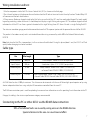
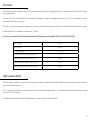
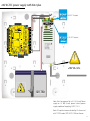
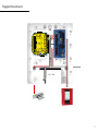
12V DC PoE+ power supply in cabinet with Net2 plus
+12V DC Outputs
Combined data and
power from a PSE (Power
source equipment)
This LED is on when the
input supply is healthy
This LED is on when the
unit is operating in high
power mode
Ethernet data

9 10
The PoE (Power over Ethernet) supply is designed to draw power from a network cable that is provided with a remote PSE. (Power
source equipment).
This unit splits Ethernet data from the DC voltage. The voltage is available at two power connectors as 12V DC and the data is passed
unaltered to the Ethernet Out port.
This allows a Net2 plus to receive its power and data over a single cable connection without the need for an additional power supply.
Do Not Connect To A Receptacle Controlled By A Switch.
UL testing was conducted with product powered from Phihong injector models PoE31U-1At and PSA16U-480
Overview
Input Voltage 36-57V DC
Input Current 0.83 A
12V Output voltage 12 - 12.2V DC
Load output current (PoE+ 802.3at type 2) 1.5 A
Load output power (PoE+ 802.3at type 2) 20.4 W
Load output current (802.3af - 802.3at type 1) 0.8 A
Load output power (802.3af - 802.3at type 1) 10.36 W
The PoE+ power supply can be used in the high power mode (see specication table) if the power source equipment can detect this
request for additional power.
This is achieved by the Paxton supply through a hardware indication (capacitance). It is not able to provide this conrmation through
software (DLL classication).
Compliance with IEEE 802.3 (at or af) specications was not veried as part of UL294/B
High power mode

11
Following the completed installation of this equipment, no further maintenance or testing is required. It is advisable to ensure that any
third party backup power supplies or recovery procedures are checked regularly to ensure that the operation of the Paxton system is
not compromised. This product is not suitable for retail sale. All warranties are invalid if this product is not installed by a trained
technician.
Maintenance
1. Mount the cabinet as instructed on the rst page.
2. Connect the network cable to PoE In.
3. The Power LED will illuminate if power is available on this data line.
4. The PoE+ LED will illuminate if the high power rating is available.
5. 12V DC power is available at the two output connectors.
6. Network data is available at ‘Ethernet Out’
Installation

11 12
12
12V
7Ah
+
-
13.8V DC
+
-
+24V DC
24V AC/DC
!
!
V42
V0
V0
V21
V0
V21
V0
V0
USP
Data/D0
Clock/D1
0V
Data/D0
Clock/D1
1
2
12V
LED
LED
LED
LED
LED
LED
12V DC
12V DC
I
Paxton
Net2 plus
Net2 plus
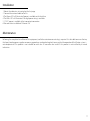
24V AC/DC power supply with Net2 plus
Note: Must be powered by a UL 294 Listed, Power
supply or UL 603 Listed, power limited, power
supply capable of supplying 24VDC, 2.3 A.
13.8V DC Outputs
+24V DC Outputs
Note: AC input has been evaluated by UL when used
with CODEX model SEP-245OU-OE6 transformer

13
Anchor points are supplied inside the case to secure the incoming supply cable. There are also ‘knock-outs’ in the case to allow
convenient access for the cable.
Where appropriate, ensure a suitable gland or grommet is used when passing the input power cable through holes in the cabinet.
The battery backup function will not work until this unit has rst been connected to the input supply. It is the loss of this supply that
switches the unit to battery power.
1. Mount the cabinet as instructed on the rst page.
2. Connect the input power.
3. The Power LED will illuminate when the input supply is healthy
4. 12V DC power is available at the two output connectors.
5. 24V DC power is available at the two output connectors.
Input Connection
Installation
Following the completed installation of this equipment, no further maintenance or testing is required. It is advisable to ensure that any
third party backup power supplies or recovery procedures are checked regularly to ensure that the operation of the Paxton system is
not compromised.
Maintenance
All wiring, other than power wiring, intended to be less than 30 meters.
Input Voltage 24v AC/DC Current
Input current N/A 2.3A
Battery Input 12v DC 2.3A
Output (12v) 13.8v DC 2 A
Output PSU Contact only N/A
Output (24v) 24v DC 0.75 A
Battery Output 12.5v DC 2 A

13 14
14
V21
V0
V21
V0
V42
V0
USP
V0
12V
7Ah
V21
V0
V21
V0
V42
V0
USP
V0
12V
7Ah
Status Lights
Green This LED is on when the input supply is healthy.
Red This LED is on when the input supply has failed - Power is being supplied by the battery.

15
12V
24V
!
!
V21
V0
V21
V0
V42
V0
USP
V0
12V
7Ah
SAFETY WARNING
RISK OF EXPLOSION IF BATTERY IS REPLACED BY AN INCORRECT TYPE.
DISPOSE OF USED BATTERIES ACCORDING TO THE INSTRUCTIONS.

15 16
24V AC Power supply with trigger disconnect
0V
0V
0V
N.C.
N.O
2
COM
N.C.
N.O
COM
Data/D0
Clock/D1
0V
Data/D0
Clock/D1
N.O
12V - 24V
12V
1
2
12V
LED
LED
LED
12V
LED
LED
LED
LED
12V DC
12V DC
1
Paxton
12V - 24V
12V
LED
V0
12V 7Ah
or
24 V DC
24V AC
!
!
+-
+12V DC
+ 24V DC
+12V DC
or
ON
ON - 24 V
OFF - 12 V
SW 1
AUX+
AUX-
BAT-
BAT+
AC
AC
Note: Must be powered by a UL 294 Listed,
Power limited, Power supply or UL 603 Listed,
Power limited, Power supply capable of
supplying 24V AC, 40 VA.

17
12V 7Ah
LOCK +
COM -
AUX +
AUX -
BAT +
BAT -
AC
AC
TRG1
TRG2
0V
0V
0V
N.C.
N.O
2
COM
N.C.
N.O
COM
Data/D0
Clock/D1
0V
10
100
Data/D0
Clock/D1
N.O
12V - 24V
12V
1
2
12V
LED
LED
LED
12V
LED
LED
LED
LED
12V DC
12V DC
1
Paxton
12V - 24V
12V
LED
Trigger Disconnect

17 18
Overview
AL177ULB is a power-limited power supply/charger that converts a 24VAC input into two (2) individual PTC protected 12VDC or 24VDC
outputs (See Specication). They are intended for use in applications requiring UL listing for Access Control (UL 294) and applications
requiring an interface with Fire Alarm Control Panels.
Terminal Legend Function/Description
AC Low Voltage AC input
TRG1 & TRG2 These input terminals are designed to connect to the
normally closed outputs of an access control or re alarm
relay. These terminals control [LOCK+], and [STRIKE+],
as well as AL177ULB output relay contacts [NC., NO.,C]
LOCK+ This terminal provides DC output voltage when [TRG1]
and [TRG2] are shorted together and are typically used to
power Mag Locks.
STRIKE+ This terminal provides DC output voltage when [TRG1]
and [TRG2] are unshorted and are typically used to
power Electric Strikes.
N.C., N.O., C Isolated dry Form “C” contacts. Shorting [TRG1] and
[TRG2] together causes these contacts to switch. They
are typically used for controlling multiple AL177ULBs with
re alarm tie-in
AUX+ Continuous positive (+) DC power output voltage. It is
not aected by TRG1, TRG2 operation.
COM- Common negative (-) output (ground)
FACP Spare wiring terminal used for re alarm tie-in application
+BAT- Stand-by battery connections
AC fail N.C., C, N.O., Used to notify loss of AC e.g. connect audible device or
alarm panel relay normally energized when AC power is
present. Contact rating 1A @ 28VDC
Terminal Identication

19
Maintenance
Following the completed installation of this equipment, no further maintenance or testing is required. It is advisable to ensure that any
third party backup power supplies or recovery procedures are checked regularly to ensure that the operation of the Paxton system is
not compromised. This product is not suitable for retail sale. All warranties are invalid if this product is not installed by a trained
technician.
Installation
The AL177ULB should be installed in accordance with article 760 of The National Electrical code (NFPA 70) or The National Fire Alarm Code (NFPA
72) as well as all applicable Local Codes
1. Mount the cabinet as instructed on the rst page.
2. Mount the AL177ULB in the desired location/enclosure.
3. Connect 24VAC, 40VA transformer to the terminals marked [AC, AC].
Use 18 AWG or larger for all power connections (Battery, DC, Output).
Use 22 AWG to 18 AWG for power-limited circuits (trigger inputs, dry outputs).
Keep power-limited wiring separate from non power-limited wiring (AC input, Battery Wires). Minimum 0.25” spacing must be provided.
4.Set the AL177ULB to the desired DC output voltage by setting switch SW1 [1&2] to the appropriate position.
5. Measure output voltage before connecting devices. This helps avoiding potential damage.
6. Connect battery to the terminals marked [+BAT-] on the unit (battery leads included). Use two (2) 12VDC batteries connected in series for 24VDC
operation.
Note: for Access control applications batteries are optional. When batteries are not used, a loss of AC will result in the loss of the output voltage.
when the use of stand-buy batteries is desired, they must be lead acid or gel type.
7. Connect appropriate signalling notication devices to AC fail supervisory relay outputs. Note: To meet UL requirements, AC supervisory outputs
must be connected to the zone of Alarm Control Panel or to visual AC trouble indicator.
Output VDC SW1
Switch position 1 & 2
12
OFF
24V ON
Input
Output
24V AC 40VA
12V DC 1.75A
or
24V DC 0.9A
La page est en cours de chargement...
La page est en cours de chargement...
La page est en cours de chargement...
La page est en cours de chargement...
La page est en cours de chargement...
La page est en cours de chargement...
La page est en cours de chargement...
La page est en cours de chargement...
-
 1
1
-
 2
2
-
 3
3
-
 4
4
-
 5
5
-
 6
6
-
 7
7
-
 8
8
-
 9
9
-
 10
10
-
 11
11
-
 12
12
-
 13
13
-
 14
14
-
 15
15
-
 16
16
-
 17
17
-
 18
18
-
 19
19
-
 20
20
-
 21
21
-
 22
22
-
 23
23
-
 24
24
-
 25
25
-
 26
26
-
 27
27
-
 28
28


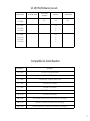
dans d''autres langues
Documents connexes
-
Paxton ins-20603 Mode d'emploi
-
-
-
-
-
-
-
-
-
Autres documents
-
 DMP 277 Trouble Annunciator Guide d'installation
-
 Digital Monitoring Products X1 SERIES SINGLE-DOOR AND MULTI-DOOR ACCESS CONTROLLER Compliance Guide
-
ViziT EXIT 300 Mode d'emploi
-
Gianni Industries GK750N Guide d'installation
-
Verkada AD31 Mode d'emploi
-
Samsung SSA-P400T Manuel utilisateur
-
 Farpointe Data CSR-35 Mode d'emploi
-
Velleman HAA2801 Guide d'installation
-
Farpointe Data CONEKT5 Mode d'emploi
-
Legrand Lighting Integrator DL Card Guide d'installation


