
1998 by Sony Corporation
3-864-641-12 (2)
VPL-SC50U
VPL-SC50E
VPL-SC50M
Operating Instructions
Mode d’emploi
Manual de instrucciones
F
ES
LCD Data Projector
EN

2 (EN)
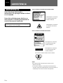
To prevent fire or shock hazard, do not
expose the unit to rain or moisture.
To avoid electrical shock, do not open the
cabinet. Refer servicing to qualified
personnel only.
This symbol is intended to alert the
user to the presence of uninsulated
“dangerous voltage” within the
product’s enclosure that may be of
sufficient magnitude to constitute a risk
of electric shock to persons.
This symbol is intended to alert the
user to the presence of important
operating and maintenance (servicing)
instructions in the literature
accompanying the appliance.
English
WARNING
This label is located on the
rear of the Remote
Commander.
This label is located on the
rear of the Remote
Commander.
LASER RADIATION
DO NOT STARE INTO BEAM
CLASS 2 LASER PRODUCT
RAYONNEMENT LASER
NE PAS REGARDER DANS LE FAISCEAU
APPAREIL A LASER DE CLASSE 2
LASER–STRAHLING
NIGHT IN DEN STRAHL BLICKEN
LASER KLASSE 2
MAX OUTPUT:1mW
WAVE LENGTH:670nm
LASER RADIATION
DO NOT STARE INTO BEAM
WAVE LENGTH:670nm
MAX OUTPUT:1mW
CLASS II LASER PRODUCT
COMPLIES WITH DHHS 21 CFR
SUBCHAPTER J
SONY CORPORATION
6-7-35 KITASHINAGAWA
SHINAGAWA-KU,TOKYO,JAPAN
A
MANUFACTURED;
CAUTION
Caution
use of controls or adjustments or performance of procedures
other than those specified herein may result in hazardous
radiation exposure.
Notes
• Do not aim the laser at people or not look into the laser
transmitter.
• When the Remote Commander causes malfunction, consult
with qualified Sony personnel. We change the Remote
Commander as new one according to the guarantee.
AVOID EXPOSURE
-
LASER
RADIATION IS EMITTED
FROM THIS APERTURE.
This label is located on the
rear of the Remote
Commander.
Laser light shines out of this window.
For the customers in the USA
This equipment has been tested and found to comply with
the limits for a Class A digital device, pursuant to Part 15 of
the FCC Rules. These limits are designed to provide
reasonable protection against harmful interference when the
equipment is operated in a commercial environment. This
equipment generates, uses, and can radiate radio frequency
energy and, if not installed and used in accordance with the
instruction manual, may cause harmful interference to radio
communications. Operation of this equipment in a residential
area is likely to cause harmful interference in which case the
user will be required to correct the interference at his own
expense.
You are cautioned that any changes or modifications not
expressly approved in this manual could void your authority
to operate this equipment.
For the customers of VPL-SC50E/SC50M
For the customers of VPL-SC50U
This label is located on the
side of the Remote
Commander.

3 (EN)
For the customers in Canada
This Class A digital apparatus complies with Canadian ICES-
003.
For the customers in the United Kingdom
WARNING
THIS APPARATUS MUST BE EARTHED
IMPORTANT
The wires in this mains lead are coloured in accordance with
the following code:
Green-and-Yellow: Earth
Blue: Neutral
Brown: Live
As the colours of the wires in the mains lead of this apparatus
may not correspond with the coloured markings identifying the
terminals in your plug proceed as follows:
The wire which is coloured green-and-yellow must be
connected to the terminal in the plug which is marked by the
letter E or by the safety earth symbol Y or coloured green or
green-and-yellow.
The wire which is coloured blue must be connected to the
terminal which is marked with the letter N or coloured black.
The wire which is coloured brown must be connected to the
terminal which is marked with the letter L or coloured red.
Voor de klanten in Nederland
Bij dit produkt zijn batterijen geleverd. Wanneer
deze leeg zijn, moet u ze niet weggooien maar
inleveren als KCA.
The socket-outlet should be installed near the equipment
and be easily accessible.

4 (EN)

5 (EN)
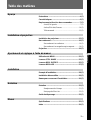
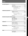
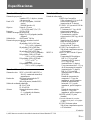
Table of Contents
English
EN
Overview
Precautions ................................................................6 (EN)
Features......................................................................8 (EN)
Location and Function of Controls..........................9 (EN)
Front/Left Side ..........................................................9 (EN)
Rear/Right Side/Bottom..........................................12 (EN)
Remote Commander ...............................................15 (EN)
Setting up and projecting
Installing the Projector............................................17 (EN)
Connecting...............................................................18 (EN)
Connecting with a Computer ..................................18 (EN)
Connecting with a VCR/Component Equipment....20 (EN)
Projecting .................................................................21 (EN)
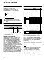
Adjustments and settings using the menu
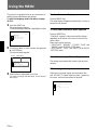
Using the MENU.......................................................24 (EN)
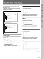
The PICTURE CTRL Menu ......................................25 (EN)
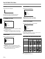
The INPUT SETTING Menu .....................................27 (EN)
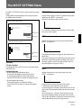
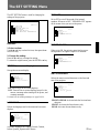
The SET SETTING Menu .........................................29 (EN)
Installation
Installation Example................................................30 (EN)
Unsuitable Installation ............................................31 (EN)
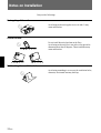
Notes on Installation ...............................................32 (EN)
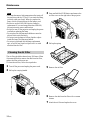
Maintenance
Maintenance.............................................................33 (EN)
Replacing the Lamp ................................................33 (EN)
Cleaning the Air Filter ............................................34 (EN)
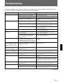
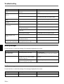
Troubleshooting ......................................................35 (EN)
Other
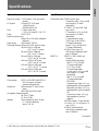
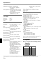
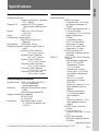
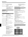
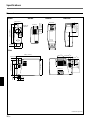
Specifications ..........................................................37 (EN)
Index .........................................................................41 (EN)

6 (EN)
On safety
•Check that the operating voltage of your unit is identical with the voltage
of your local power supply. If voltage adaptation is required, consult with
qualified Sony personnel.
•Should any liquid or solid object fall into the cabinet, unplug the unit and
have it checked by qualified personnel before operating it further.
•Unplug the unit from the wall outlet if it is not to be used for several
days.
•To disconnect the cord, pull it out by the plug. Never pull the cord itself.
•The wall outlet should be near the unit and easily accessible.
•The unit is not disconnected to the AC power source (mains) as long as it
is connected to the wall outlet, even if the unit itself has been turned off.
•Do not look into the lens while the lamp is on.
•Do not aim the laser at people or not look into the laser transmitter.
•Do not place your hand or objects near the ventilation holes — the air
coming out is hot.
•Be careful not to catch your fingers by the adjuster when you lift up the
projector. Do not push hard on the top of the projector with the adjuster
out.
On illumination
•To obtain the best picture, the front of the screen should not be exposed
to direct lighting or sunlight.
•Ceiling-mounted spot lighting is recommended. Use a cover over
fluorescent lamps to avoid lowering the contrast ratio.
•Cover any windows that face the screen with opaque draperies.
•It is desirable to install the projector in a room where floor and walls are
not of light-reflecting material. If the floor and walls are of reflecting
material, it is recommended that the carpet and wall paper be changed to
a dark color.
On preventing internal heat build-up
After you turn off the power with the I /
u
key on the Remote Commander
or on the control panel, do not disconnect the unit from the wall outlet
while the cooling fan is still running.
Caution
The projector is equipped with ventilation holes (intake) on the right side
and ventilation holes (exhaust) on both sides and rear. Do not block or
place anything near these holes, or internal heat build-up may occur,
causing picture degradation or damage to the projector.
Precautions

7 (EN)
On cleaning
•To keep the cabinet looking new, periodically clean it with a soft cloth.
Stubborn stains may be removed with a cloth lightly dampened with a
mild detergent solution. Never use strong solvents, such as thinner,
benzene, or abrasive cleansers, since these will damage the cabinet.
•Avoid touching the lens. To remove dust on the lens, use a soft dry cloth.
Do not use a damp cloth, detergent solution, or thinner.
•Clean the filter at regular intervals.
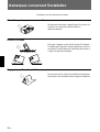
On repacking
•Save the original shipping carton and packing material; they will come in
handy if you ever have to ship your unit. For maximum protection,
repack your unit as it was originally packed at the factory.
Overview

8 (EN)
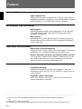
Features
High portability
•Light weight/small size
This projector has come to miniaturized to 3.7 kg (8 lb 3 oz) of mass by
adopting magnesium die-casting body. And a carrying handle is epuipped
with the projector. You can easily carry it with your computer.
High brightness, high picture quality
•High brightness
Adopting the new developed optical system and the 120 W UHP lamp
allow high brightness (light output 500 ANSI lumen) and excellent
uniformity on the picture.
•High resolution
By adopting three 0.9-inch, 480,000-pixel SVGA panels, this projector
offers resolution of 800 × 600 dots for RGB input and 600 horizontal TV
lines for video input.
Simple setup, easy presentation
•Simple setup with external equipment
This projector has 22 kinds of preset data for input signals. You can get a
suitable picture by connecting an equipment with supplied cable.
•Remote Commander with mouse control and laser pointer functions
You can operate a computer with the Remote Commander since the unit
has a build-in mouse receiver. For your presentation, you can use the
laser pointer built in the Remote Commander as well.
Accepts various input signals
•Compatible input signals
This projector accepts video signals of the composite, S video, and
component as well as the VGA
1)
, SVGA
1)
and XGA
1) 2)
signals, which all
can be displayed.
•Compatible with five color systems
NTSC, PAL, SECAM, NTSC 4.43
3)
, or PAL-M color system can be
selected automatically or manually.
..........................................................................................................................................................................................................
1) VGA, SVGA and XGA are registered trademarks of the International Business Machines Corporation,
U.S.A.
2) Compressed XGA signal is reprodued.
3) NTSC4.43 is the color system used when playing back a video recorded on NTSC on a NTSC4.43 system VCR.

9 (EN)
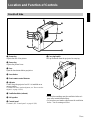
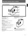
Location and Function of Controls
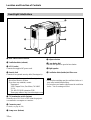
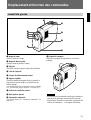
Front/Left Side
1 Zoom ring
Adjusts the size of the picture.
2 Focus ring
Adjusts the picture focus.
3 Lens
Open the lens shutter before projection.
4 Lens shutter
5 Front remote control detector
6 Adjuster
Used to keep the projector level if it is installed on an
uneven surface.
For details on how to use the adjusters, see “How to use the
adjuster” on page 13 (EN).
7 Ventilation holes (exhaust)
8 Left speaker
9 Control panel
For details, see “Control panel” on page 10 (EN).
0 Carrying handle
Pull up the handle from the projector for carrying.
Notes
•Do not place anything near the ventilation holes as it
may cause internal heat build-up.
•Do not place your hand or objects near the ventilation
holes — the air coming out is hot.
5
3
4
2
1
9
8
7
6
0

10 (EN)
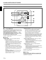
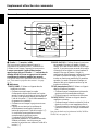
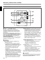
Control panel
Location and Function of Controls
1
I / u
(
on / standby
)
key
Turns on and off the projector when the projector is in
the standby mode. The ON/STANDBY indicator lights
in green when the power is turned on.
When turning off the power, press the
I / u
key
twice following the message on the screen, or press
and hold the key for about one second.
For details on steps for turning off the power, see “To turn off
the power” on page 23 (EN).
2 Indicators
ON/STANDBY: Lights up or flashes under the
following conditions:
• Lights in red when the AC power cord is
plugged into the wall outlet. Once in the standby
mode, you can turn on the projector with the
I / u
key on the Remote Commander or on the
control panel.
• Lights in green when the power is turned on.
• Flashes in green while the cooling fan runs after
turning off the power with the
I / u
key. The fan
runs for about 90 seconds after turning off the
power.
The ON/STANDBY indicator flashes quickly
for the first 30 seconds.
During this time, you cannot turn the power
back on with the
I / u
key.
POWER SAVING: Lights up when the projector is
in the power saving mode. When POWER
SAVING in the SET SETTING menu is set to
ON, the projector goes into the power saving
mode if no signal is input for 10 minutes.
Although the lamp goes out, the cooling fan keeps
running. In the power saving mode, any key does
not function for the first 30 seconds. The power
saving mode is canceled when a signal is input or
any key is pressed.
TEMP (Temperature)/FAN: Lights up or flashes
under the following conditions:
• Lights up when temperature inside the projector
becomes unusually high.
• Flashes when the fan is broken.
LAMP/COVER: Lights up or flashes under the
following conditions:
• Lights up when the lamp has reached the end of
its life or becomes a high temperature.
• Flashes when the lamp cover or air filter cover is
not secured firmly.
For details on the LAMP/COVER and the TEMP/FAN
indicators, see page 36 (EN).
3 INPUT key
Selects the input signal. Each time you press the key,
the input signal switches between video/audio input
and INPUT-A connector.
MENU
ENTERRESET
INPUT
ON
/STANDBY
LIGHT
DP
VOLUME I/ u
POWER
SAVING
TEMP
/FAN
LAMP
/COVER
5
2
6
7
8
0
9
1
4
3

11 (EN)
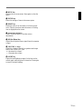
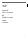
4 MENU key
Displays the on-screen menu. Press again to clear the
menu.
5 ENTER key
Enters the settings of items in the menu system.
6 RESET key
Resets the value of an item back to its factory preset
value. This key functions when the menu or a setting
item is displayed on the screen.
7 Arrow keys (V/v/B/b)
Used to select the menu or to make various
adjustments.
8 DP
(
Dot Phase
)
key
Adjusts the dot phase when a signal from the computer
is input.
9 VOLUME +/– keys
Adjust the volume of the built-in speakers and output
level of the AUDIO OUT jack.
+ : Increases the volume.
– : Decreases the volume.
!º LIGHT key
Lights the back lighting (orange) for the keys on the
control panel when the power is turned on. Press again
to turn off the back lighting.

12 (EN)
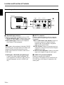
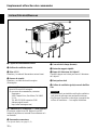
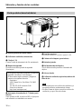
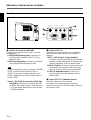
1 Rear remote control detector
2 Ventilation holes (exhaust)
3 AC IN socket
Connects the supplied AC power cord.
4 Security lock
Connects to an optional security cable (Kensington’s).
The security lock corresponds to Kensington’s
MicroSaver Security System.
If you have any comment, contact
Kensington
2853 Campus Drive, San Mates, CA 94403
U.S.A.
Tel: 800-535-4242: extension 3348
Home page address: http://www.kensington.com/
5 75Ω termination switch (bottom)
Normally set to ON. Set it to OFF when the projector
is connected to a computer or a monitor.
6 Connector panel
For details, see page 14 (EN).
7 Lamp cover (bottom)
Rear/Right Side/Bottom
Location and Function of Controls
8 Adjuster button
9 Lens shutter dial
Turn the dial upward to open the lens shutter.
0 Right speaker
!¡ Ventilation holes (intake)/air filter cover
Notes
•Do not place anything near the ventilation holes as it
may cause internal heat build-up.
•Do not place your hand or objects near the ventilation
holes — the air coming out is hot.
1
3
4 6 75
8
9
0
!¡
2

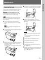
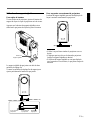
13 (EN)
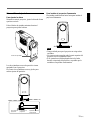
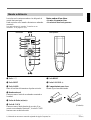
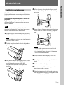
To raise
the projector
To lower
the projector
Adjuster button
How to use the adjuster
To adjust height
While lifting the projector, adjust the height so that the
projector becomes level.
Press the adjuster button while lifting the projector to
adjust the height.
The two fine screw-up adjusters are equipped with the
projector.
As for the fine screw-up adjusters, turn them for fine
adjustment.
To stand the projector firmly
The adjuster can be stretched outwards to stand the
projector firmly.
Notes
•Be careful not to let the projector down on your
fingers.
•Do not push hard on the top of the projector with the
adjusters out.
•If the adjuster is not stretched out toward right and
left sides of the projector, the unit may be
overbalanced.
Fine screw-up
adjuster

14 (EN)
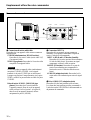
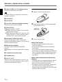
Connector panel
1 Video/audio input connector
Connect to external video equipment such as a VCR.
S VIDEO (mini DIN 4-pin): Connects to the S video
output (Y/C video output) of a video equipment.
VIDEO (phono type): Connects to the composite
video output of video equipment.
Note
If you connect video equipment to both the S VIDEO
and VIDEO jacks, the signal from the S VIDEO jack
is selected. When projecting the picture via the
VIDEO jack, be sure not to connect a cable to the S
VIDEO jack.
AUDIO input L (MONO)/R jacks (phono type):
Connect to the audio output of equipment. For
stereo equipment, use both the L and R jacks; for
monaural equipment, use the L (MONO) jack
only.
2 INPUT-A connector
Connect to external equipment such as a computer.
You can control the mouse signal with the Remote
Commander.
INPUT A (HD D-sub 15-pin, female): Connects to
the monitor output on a computer using the
supplied cable. When inputting a component
signal, use the optional cable.
MOUSE (13-pin): Connects to the mouse port on a
computer to control the mouse function using the
supplied mouse cable.
AUDIO IN (stereo minijack): Connects to the audio
output on a computer to input the audio signal.
3 AUDIO OUT jack (stereo minijack)
Connects to external active speakers.
The volume of the speakers can be controlled by the
VOLUME keys on the Remote Commander or the
control panel.
Right side
S VIDEO VIDEO
INPUT A MOUSE
AUDIO OUT
AUDIO IN
L-AUDIO-R
1
2
3
Location and Function of Controls

15 (EN)
The keys which have the same names as on the control
panel function identically.
You can control a connected computer using the
Remote Commander.
For details, see “Connecting with a Computer” on page
18 (EN).
Remote Commander
Notes on laser beam
•Do not look into the laser transmitter.
•Do not aim the laser at people.
1
I / u
key
2 INPUT key
3 LASER key
Emits laser beam from the laser transmitter when you
press this key.
4 Joy stick
Functions as a mouse of a computer connected to the
unit.
5 Arrow keys (V/v/B/b)
6 R CLICK key
Functions as a right button on a mouse. When
connected to a Macintosh
1)
computer, the R CLICK
key functions as a mouse button.
Front Rear
1) Macintosh is a registered trademark of Apple Computer, Inc.
..........................................................................................................................................................................................................
7 RESET key
8 VOLUME +/– keys
9 Strap holder
Attaches the supplied strap.
(Continued)
COMMAND
MUTING
I / u
INPUT
APA
MENU
LASER
V
bB
v
ENTER
RESET
VOLUME
+
–
R CLICK
PICTUREAUDIO
ONOFF
1
2
3
5
7
6
8
4
!¡
!™
!£
!¢
!∞
!§
!¶ !•
9, 0
!ª

16 (EN)
Location and Function of Controls
!º CONTROL S OUT jack (stereo minijack)
This jack does not operated with this unit.
Note
The Remote Commander does not function if the cable
is connected to this jack.
!¡ ENTER key
!™ MENU key
!£ APA (Auto Pixel Alignment) key
This key does not operated with this unit.
!¢ MUTING keys
Cut off the picture and sound.
PICTURE: Cuts off the picture. Press again to
restore the picture.
AUDIO: Cuts off the sound from speakers and
AUDIO OUT jack. Press again or press the
VOLUME + key to restore the sound.
!∞ COMMAND ON/OFF switch
When this switch is set to OFF, no key on the Remote
Commander function. This saves the battery power.
!§ Transmission indicator
Lights up when you press a key on the Remote
Commander.
This indicator does not light up when you use the laser
pointer.
!¶ Infrared transmitter
!• Laser transmitter
!ª L CLICK key
Functions as a left button on a mouse. When connected
to a Macintosh computer, the L CLICK key functions
as a mouse button.
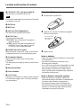
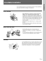
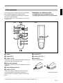
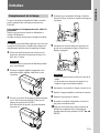
Be sure to install
the battery from
the ’ side.
Battery installation
1 Push and slide to open the lid.
2 Install the two size AA (R6) batteries (supplied)
with the correct polarity.
3 Replace the lid.
Notes on batteries
•Make sure that the battery orientation is correct when
inserting batteries.
•Do not mix an old battery with a new one, or
different types of batteries.
•If you will not use the Remote Commander for a long
time, remove the batteries to avoid damage from
battery leakage. If batteries have leaked, remove
them, wipe the battery compartment dry and replace
the batteries with new ones.
Notes on Remote Commander operation
•Make sure that there is nothing to obstruct the
infrared beam between the Remote Commander and
the remote control detector on the projector.
•The operation range is limited. The shorter the
distance between the Remote Commander and the
projector is, the wider the angle within which the
commander can control the projector.

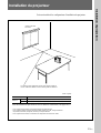
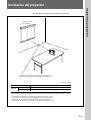
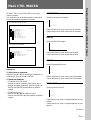
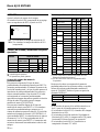
17 (EN)
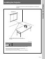
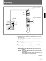
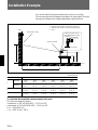
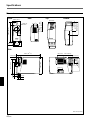
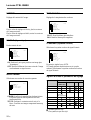
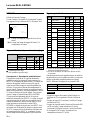
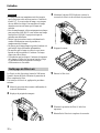
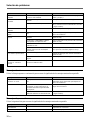
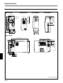
This section describes the installation arrangements for installing the
projector.
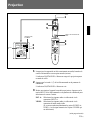
Installing the Projector
Horizontal center
of the screen
The distance between the lens and the screen varies
depending on the size of the screen. Use the following table
as a guide.
Setting up and projecting
Screen size (inches) 40 60 80 100 120 150
Distance
Minimum 1.4 (4.6) 2.2 (7.1) 2.9 (9.5) 3.6 (11.9) 4.4 (14.4) 5.5 (18.1)
Maximum 1.6 (5.4) 2.5 (8.1) 3.3 (10.9) 4.2 (13.7) 5.0 (16.5) 6.3 (20.6)
Unit: m (feet)
For detailed information on installation measurements, see page 30 (EN).
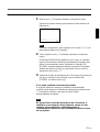
• When the VGA signal is input, the picture size becomes smaller by 20%.
• When the Macintosh 16-inch mode (832 × 624) signal is input, the outer image (32
dots (horizontal) /24 lines (vertical)) is not displayed.
• When the XGA signal is input, the resolution is compressed to the 797 × 598 format.

18 (EN)
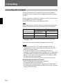
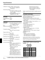
Connecting
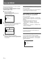
Connecting with a Computer
This section describes how to connect the projector with a computer.
For details on how to connect a VCR or component equipment, see page
20 (EN).
When the projector is connected to a computer, you can control the mouse
of a computer by the Remote Commander.
The R/L CLICK keys and joy stick function as follows.
Note
Make sure that there is nothing to obstruct the infrared beam between the
Remote Commander and the remoter control detector on the projector.
Key and joy stick
IBM PC/AT
a)
Macintosh
compatible, Serial
R CLICK (front) Right button Mouse button
L CLICK (rear) Left button Mouse button
Joy stick Corresponds with the movements of the mouse
a) IBM PC/AT is a registered trademark of International Business Machines
Corporation, U.S.A.
Also refer to the instruction manual of equipment to be connected.
Notes
•This unit accepts the VGA, SVGA and XGA signals. However, we
recommend you to set the output mode of your computer to the SVGA
mode for the external monitor.
•If you set your computer, such as a notebook type IBM PC/AT
compatible, to output the signal to both the display of your computer and
the external monitor, the picture of the external monitor may not appear
properly. In such cases, set the output mode of your computer to output
the signal to only the external monitor.
For details, refer to the operating instructions supplied with your computer.
When making connections, be sure to:
•turn off all equipment before making any connections.
•use the proper cables for each connection.
•insert the plugs of the cables properly; plugs that are not fully inserted
often generate noise. When pulling out a cable, be sure to pull it out from
the plug, not the cable itself.
Function

19 (EN)
S VIDEO VIDEO
INPUT A MOUSE
AUDIO OUT
AUDIO IN
L-AUDIO-R
S VIDEO VIDEO
INPUT A MOUSE
AUDIO OUT
AUDIO IN
L-AUDIO-R
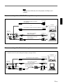
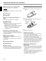
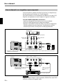
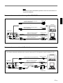
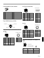
When connecting with an IBM PC/AT compatible computer
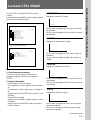
When connecting with a Macintosh computer
Computer
Right side
SIC-S21 Mouse cable for serial port
(not supplied)
to serial port
to mouse port
SIC-S22 Mouse cable for PS/2 port (supplied)
to audio out
Stereo audio connecting
cable (not supplied)
to monitor out
Right side
SIC-S20 Mouse cable (supplied)
to mouse port
to audio out
Stereo audio connecting
cable (not supplied)
to monitor out
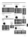
SMF-401 HD D-sub 15-
pin cable (supplied)
Signal adapter
(supplied)
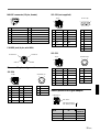
For details on the DIP switch setting of the adapter, see page 39 (EN).
Note
Supplied mouse cables may not work properly according to your
computer.
or
Computer
SMF-401 HD D-sub 15-pin
cable (supplied)

20 (EN)
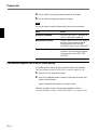
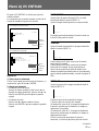
Note
Set the aspect ratio using ASPECT in the INPUT SETTING menu
according to the input signal.
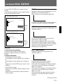
Right side
Component equipment
to component output
SMF-402 Signal Cable (not supplied)
3X phono jack ˜ HD D-sub
15-pin (male)
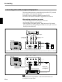
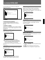
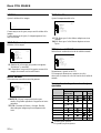
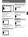
Connecting with a VCR/Component Equipment
This section describes how to connect the projector with a VCR, external
active speakers, and component equipment.
For details on how to connect a computer, see page 18 (EN).
Also refer to the instruction manuals of equipment to be connected.
When making connections, be sure to:
•turn off all equipment before making any connections.
•use the proper cables for each connection.
•insert the plugs of the cables properly; plugs that are not fully inserted
often generate noise. When pulling out a cable, be sure to pull it out from
the plug, not the cable itself.
S-Video cable
(not supplied)
Audio/video cable
(supplied)
Active speakers
to audio/video outputs
1)
to S video
output
1)
VCR
Right side
Connecting
1) When both the S VIDEO and VIDEO jacks are connected to the external equipment, the input signal from the S VIDEO jack is selected.
Stereo audio
connecting cable
(not supplied)
S VIDEO VIDEO
INPUT A MOUSE
AUDIO OUT
AUDIO IN
L-AUDIO-R
S VIDEO VIDEO
INPUT A MOUSE
AUDIO OUT
AUDIO IN
L-AUDIO-R
La page charge ...
La page charge ...
La page charge ...
La page charge ...
La page charge ...
La page charge ...
La page charge ...
La page charge ...
La page charge ...
La page charge ...
La page charge ...
La page charge ...
La page charge ...
La page charge ...
La page charge ...
La page charge ...
La page charge ...
La page charge ...
La page charge ...
La page charge ...
La page charge ...
La page charge ...
La page charge ...
La page charge ...
La page charge ...
La page charge ...
La page charge ...
La page charge ...
La page charge ...
La page charge ...
La page charge ...
La page charge ...
La page charge ...
La page charge ...
La page charge ...
La page charge ...
La page charge ...
La page charge ...
La page charge ...
La page charge ...
La page charge ...
La page charge ...
La page charge ...
La page charge ...
La page charge ...
La page charge ...
La page charge ...
La page charge ...
La page charge ...
La page charge ...
La page charge ...
La page charge ...
La page charge ...
La page charge ...
La page charge ...
La page charge ...
La page charge ...
La page charge ...
La page charge ...
La page charge ...
La page charge ...
La page charge ...
La page charge ...
La page charge ...
La page charge ...
La page charge ...
La page charge ...
La page charge ...
La page charge ...
La page charge ...
La page charge ...
La page charge ...
La page charge ...
La page charge ...
La page charge ...
La page charge ...
La page charge ...
La page charge ...
La page charge ...
La page charge ...
La page charge ...
La page charge ...
La page charge ...
La page charge ...
La page charge ...
La page charge ...
La page charge ...
La page charge ...
La page charge ...
La page charge ...
La page charge ...
La page charge ...
La page charge ...
La page charge ...
La page charge ...
La page charge ...
La page charge ...
La page charge ...
La page charge ...
La page charge ...
-
 1
1
-
 2
2
-
 3
3
-
 4
4
-
 5
5
-
 6
6
-
 7
7
-
 8
8
-
 9
9
-
 10
10
-
 11
11
-
 12
12
-
 13
13
-
 14
14
-
 15
15
-
 16
16
-
 17
17
-
 18
18
-
 19
19
-
 20
20
-
 21
21
-
 22
22
-
 23
23
-
 24
24
-
 25
25
-
 26
26
-
 27
27
-
 28
28
-
 29
29
-
 30
30
-
 31
31
-
 32
32
-
 33
33
-
 34
34
-
 35
35
-
 36
36
-
 37
37
-
 38
38
-
 39
39
-
 40
40
-
 41
41
-
 42
42
-
 43
43
-
 44
44
-
 45
45
-
 46
46
-
 47
47
-
 48
48
-
 49
49
-
 50
50
-
 51
51
-
 52
52
-
 53
53
-
 54
54
-
 55
55
-
 56
56
-
 57
57
-
 58
58
-
 59
59
-
 60
60
-
 61
61
-
 62
62
-
 63
63
-
 64
64
-
 65
65
-
 66
66
-
 67
67
-
 68
68
-
 69
69
-
 70
70
-
 71
71
-
 72
72
-
 73
73
-
 74
74
-
 75
75
-
 76
76
-
 77
77
-
 78
78
-
 79
79
-
 80
80
-
 81
81
-
 82
82
-
 83
83
-
 84
84
-
 85
85
-
 86
86
-
 87
87
-
 88
88
-
 89
89
-
 90
90
-
 91
91
-
 92
92
-
 93
93
-
 94
94
-
 95
95
-
 96
96
-
 97
97
-
 98
98
-
 99
99
-
 100
100
-
 101
101
-
 102
102
-
 103
103
-
 104
104
-
 105
105
-
 106
106
-
 107
107
-
 108
108
-
 109
109
-
 110
110
-
 111
111
-
 112
112
-
 113
113
-
 114
114
-
 115
115
-
 116
116
-
 117
117
-
 118
118
-
 119
119
-
 120
120


Sony VPL-SC50E Manuel utilisateur
- Catégorie
- Projecteurs de données
- Taper
- Manuel utilisateur
dans d''autres langues
- English: Sony VPL-SC50E User manual
- español: Sony VPL-SC50E Manual de usuario