AGA AELTTDW-BLK Le manuel du propriétaire
- Catégorie
- Lave-vaisselle
- Taper
- Le manuel du propriétaire

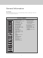
Installation
VDW302 / VDW302WS
RVDW103
/ RVDW103WS
FDW103 / FDW302
FDW103WS/ FDW302WS
CFDW103 / CFDW302
Built-In Dishwashers

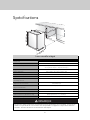
Table of Contents
Important Safety Instructions __________________________________________________________3
Tools Which May Be Needed _________________________________________________________5
Materials Which May Be Needed ______________________________________________________6
Materials Supplied ___________________________________________________________________7
Parts Supplied ___________________________________________________________________7
Dishwasher Specifications ____________________________________________________________8
Enclosure Preparation ________________________________________________________________9
Electrical Preparation _____________________________________________________________9
Preparation for Installing Mounting Brackets_________________________________________9
Adjusting Height_________________________________________________________________9
Installing the Side Trim Strips_____________________________________________________10
Preparing the Water Connection __________________________________________________11
Drain Preparation _______________________________________________________________12
Steam Protection Foil____________________________________________________________13
Installation_________________________________________________________________________14
Drain Hose Connection, Water Supply & Electrical Connections ______________________14
Preparation of Water Supply _____________________________________________________15
Electrical Connection ____________________________________________________________18
Readjusting Foot Levels _________________________________________________________19
Adjusting Moveable Kickplate ____________________________________________________19
Installing a Custom Panel ________________________________________________________21
Installer Checklist ___________________________________________________________________26
Final Instructions ___________________________________________________________________26
Service & Registration_______________________________________________________________27
2

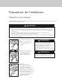
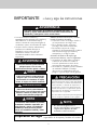
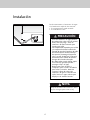
IMPORTANT
3
– Please Read and Follow
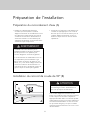
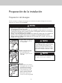
Site Preparation
It is recommended that a thorough site inspection be
conducted PRIOR to unpacking and moving this appliance.
• Please read this installation manual and
particularly the safety instructions
completely and carefully. They will save
you time and effort and help to ensure
optimum dishwasher performance.
• Be sure to observe all listed warnings and
cautions. Look particularly for the icons
with exclamation marks inside. The
information icon also will provide
important references.
WARNING
Indicates a potentially hazardous
situation which, if not avoided,
could result in death or serious injury.
CAUTION
Indicates a potentially hazardous
situation which, if not avoided,
may result in injury. It may also be used
to alert against unsafe practices.
NOTICE
Indicates a potentially hazardous
situation which, if not avoided,
may result in damage to the dishwasher,
the tableware, the equipment, or
the environment.
In addition to these instructions, the
dishwasher shall be installed:
• In accordance with all local codes or, in
absence of a local code,
• In the United States, with the national
Electric Code,
• In Canada, with the Canadian Electric
Code C22.1-latest edition/Provincial and
Municipal codes and/or local codes.
WARNING
Read these installation instructions
completely before installing and
follow them carefully. Save these
installation instructions and pass
them on to any future user.
When installing the dishwasher, follow basic
precautions, including the following:
• The dishwasher should only be converted
from cord-connected to permanently
connected by an authorized service
representative.
• Installation and repair should be
performed by a qualified installer. Work by
unqualified persons could be dangerous
and may void the warranty.
NOTICE
Installation should be performed by
an insured licensed plumber,
contractor, or trained installer.
Installation performed by persons
other than this could result in
improper installation and property
damage.
NOTICE
• Do not discard any bags or items that
come with the original package until
after the entire installation has been
completed.

4
• DO NOT operate the appliance if damaged, malfunctioning, partially disassembled, or if it
has missing or broken parts.
• Also follow the safety instructions of the use and care guide.
• To reduce the risk of electric shock, fire, or injury to persons, the installer must ensure that the
dishwasher is completely enclosed at the time of installation.
• Only connect the dishwasher to the power supply when all installation and plumbing work is
complete.
• If the dishwasher is installed in a location that experiences freezing temperatures (e.g. in a
vacation home, cabin, etc.), you must drain all the water from the dishwasher’s interior. Water
system ruptures that occur as a result of freezing are not covered by warranty.
• Dishwasher must be secured to adjacent cabinetry using the brackets provided. Failure to do
this may cause damage to property or bodily injury.
• Connect to a properly rated, protected, and sized power supply circuit to avoid electrical
overload. The dishwasher is designed for an electrical supply of 120V (volts), 60Hz (hertz),
AC, connected to a dishwasher-dedicated, properly grounded electrical circuit with a fuse or
breakers rated for 15 amperes. Electrical supply conductors shall be a minimum of #16 AWG
copper wire rated at 167°F (75°C) or higher. These requirements must be met to prevent
injury and machine damage. Consult a qualified electrician if in doubt.
• DO NOT use any extension cord or portable outlet device to connect the dishwasher to a
power supply.
• Ensure that any plastic wrappings, bags, small pieces, etc., are disposed of safely and kept
out of the reach of children. Danger of suffocation!
• Remove the dishwasher door when removing an old dishwasher from service or discarding it.
Ensure that the appliance presents no danger to children while being stored for disposal.
• Old appliances may contain materials that can be recycled. Please contact your local
recycling authority about the possibility of recycling these materials.
NOTICE
• The dishwasher drain hose must be installed with a drain loop at least 28” (710mm) off the
cabinet floor; otherwise the dishwasher may not drain properly.
• This dishwasher is intended for residential use only and should not be used in commercial
establishments.
• New Installation: If the dishwasher is a new installation, most of the work must be done
before the dishwasher is moved into place.
• Replacement: If the dishwasher is replacing another dishwasher, check the existing
dishwasher connections for compatibility with the new dishwasher, and replace parts as
necessary.
• Inspect the Dishwasher: After unpacking the dishwasher and prior to installation, thoroughly
inspect the dishwasher for possible freight or cosmetic damage. Report any damage
immediately.
To contact us, you may either call our toll-free number at 1-888-845-4641 or contact us via the
website in the US (www.vikingrange.com) or in Canada (www.brigade.ca).
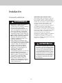
IMPORTANT– Please Read and Follow

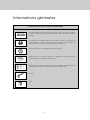
General Information
5
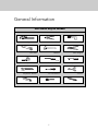
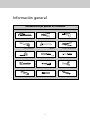
Tools Which May Be Needed
Pipe Wrench Wire Cutter Drill
Hole Saw Hammer Wire Stripper
Tape Measure Torx Screwdriver
(T20)
Phillips Screwdriver
Adjustable Wrench Slot Screwdriver Scissors
Level Brush Pencil

6
General Information
Materials Which May Be Needed
Hot Water Supply Line – Minimum 3/8” O.D. copper tubing or metal
braided dishwasher supply line.
90° elbow with 3/8” N.P.T. male threads on one leg, and sized to fit
your water supply line (copper tubing/compression fitting, or braided
hose) on the other leg.
UL listed conduit connector or strain relief.
Teflon tape or other pipe thread compound to seal plumbing
connections.
Shut-off valve and fittings appropriate for hot water supply line (copper
tubing/compression fitting, or braided hose).
Silicone.
Glue.

7
General Information
Materials Supplied
x1
x1
y.
x4
x2
x2
a.
b.
d.
e.
f.
g.
h.
c.
j.
k.
l.
o.
p.
s.
v.
n.
r.
t.
m.
x1
x1
x1
x1
x6
x1
x1
x1
x1
x1
x1
x4
x2
x2
x1
z.
x1
Dishwasher Parts Bag 1
This dishwasher bag comes with
the following parts:
a. Side Trim Strips – Left
b. Side Trim Strips – Right
c. Adjusting Wrench
d. Screws Ø 1/8”x5/8”
(Ø 3.5mmx14mm)
e. Mounting Bracket – Left
f. Mounting Bracket – Right
g. Spring Clamp
h. Screw Clamp
j. Rubber Connector
k. Kickplate Bracket – Left
l. Kickplate Bracket – Right
m. Edge Protector
n. Clips
o. Kickplate
(kickplate without slots)
p. Kickplate
r. Screws Ø 1/8”x3/8”
(Ø 3.9mmx9mm)
s. Plastic Caps
t. Screws Ø 3/16”x1/4”
(Ø 4mmx6mm)
z. Steam Protection Foil
Dishwasher Parts Bag 2
v. Screws Ø 1/8”x5/8”
(Ø 3.5mmx14mm)
y. Screws Ø 3/16”x1-3/4”
(Ø 4mmx43mm)
Parts Attached to the Rear
of the Dishwasher
a. Side Trim Strips – Left
b. Side Trim Strips – Right
o. Kickplate
(Kickplate without slots)
p. Kickplate
Parts Supplied
Parts for your dishwasher will come in several plastic bags. Check your parts bags to make sure
you have all the parts as listed below.

8
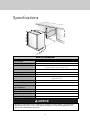
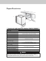
Specifications
24” max
(61.0 cm max)
24” max
(61.0 cm max)
24” max
(61.0 cm max)
Built-In Dishwasher
Overall Width
Overall Height from Floor
Overall Depth from Rear
Cutout Width
Cutout Height
Cutout Depth
Electrical Requirements
Water-Heating Element Rating
Inlet Water Temperature
Inlet Water Pressure
Operating Range
Inlet Water Hose
Drain Hose
Drain Hose High Loop Required
Approximate Shipping Weight
23-9/16” (59.8 cm)
33-7/8 (86.0 cm) min. to 35-7/8" (91.1 cm) max.
without door panel – 21 5/8” (54.9 cm)
with door panel – 22 3/16” (156.4 cm)
24" (61.0 cm)
34" (86.4 cm) min. to 36" (91.4 cm) max.
24" (61.0 cm)
12.0 amps, 120V/60 Hz; 4’ (1.2 m) electrical cord
supplied with unit
1240 watts
120°F (49°C) required
4.35 to 145 psi (.3 - 10 bar)
Minimum 3/8" OD copper tubing or braided metal water line required.
6.4' (1.9 m) drain hose provided
Height from floor – 28" (71.1 cm)
97 lbs. (44 kg)
NOTICE
Because we continually strive to improve our products, we may change our specifications
and design without prior notice. This device corresponds to the following directives: UL
749 Household Dishwasher Directive.

9
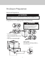
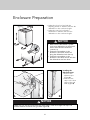
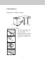
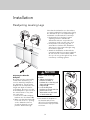
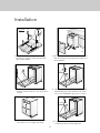
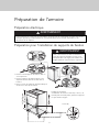
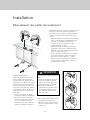
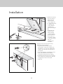
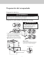
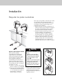
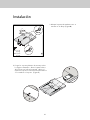
Electrical Preparation
Preparation for Installing Mounting Brackets
Enclosure Preparation
WARNING
The dishwasher is designed for an electrical supply of 120V, 60Hz, AC, connected to a
dishwasher-dedicated, properly grounded electrical circuit with a fuse or breaker rated for
15 amperes.
• Place the two mounting brackets into the
top corners of the dishwasher.
• Fix the mounting brackets (A) to the top
corners of the dishwasher, with the screws
supplied.
• Bend sides of mounting brackets (B) in
order to fix from sides (if necessary).
WARNING
Dishwasher must be secured to
adjacent cabinetry using the mounting
brackets provided. Failure to do this
may cause damage to property or
bodily injury.
Adjusting Height
If the height of the enclosure is 33-7/8” to
35-7/8” (86.1cm-91.1cm), adjust supports as
shown in the figure.
Supplied (4)

10
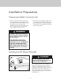
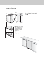
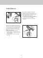
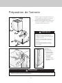
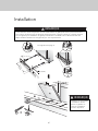
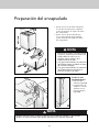
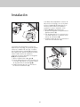
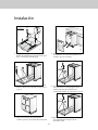
Enclosure Preparation
T20
A
B
• Adjust the front foot level with the
adjusting wrench to balance and raise the
dishwasher to the enclosure height.
• Adjust the rear foot level with a
screwdriver to balance and raise the
dishwasher to the enclosure height.
NOTICE
• Make sure the dishwasher is plumb
and notice dishwasher can be placed
with a small clearance under the
counter top.
• Turning the screwdriver in the
direction of the black arrows will
bring the dishwasher back feet up.
• Turning the screwdriver in the
direction of the white arrows will take
the dishwasher rear feet down.
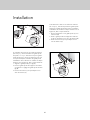
Installing the
Side Trim Strips
• Remove the
adhesive tape
(Figure A).
• Place the trim
strips on the front
edge of the side
walls (Figure B).
NOTICE
Make sure you use the correct trim strip since there is a left and a right side strip. The
flexible material should be facing forward (Figure B).

11
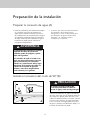
Installation Preparation
A
B
• Check with your plumbing supply sources
for the proper hose and 90° elbow and
necessary fittings for the water supply line.
This material is not supplied and must be
purchased separately.
If the water supply line is to be copper
tubing, make certain that the elbow has a
compression fitting. Apply Teflon tape or
other pipe sealant when required. Orient the
water supply connection downwards as
shown in the figure so the water line can be
easily pulled underneath or on the side of
the dishwasher.
• Install an easily accessible shut-off valve
(not supplied) in the water supply line. All
solder connections must be made before
the water line is connected to the
dishwasher’s water inlet valve. Water can
also be supplied to the dishwasher by
using a flexible braided hose line.
Preparing the Water Connection (A)
Installing the 90° Elbow Fitting (B)
WARNING
Installation should be performed by a
qualified installer. Work by unqualified
persons could be dangerous and may
void the warranty.
If the dishwasher is installed in a
location that experiences freezing
temperatures (e.g. in a vacation home,
cabin, etc.), you must drain all the
water from the dishwasher’s interior.
Water system ruptures that occur as a
result of freezing are not covered by
warranty.
CAUTION
Do not overtighten the 90° elbow.
Doing so may damage the water inlet
valve and cause a water leak.

12
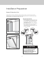
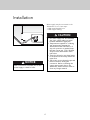
Installation Preparation
A
B
C
The dishwasher drain hose may be connected to the drain plumbing in one of three ways,
(Figures A, B, C):
Drain Preparation
NOTICE
You must add a loop at least 28”
(71.1cm) above the floor of the cabinet
and above the drain connection in the
drain hose to prevent waste water from
not draining properly and causing either
poor washing results or a bad odor.
NOTICE
Check with local ordinance for type of
air gap required.
NOTICE
• Either one of the above methods must be used or the dishwasher will not operate
properly.
• A hose that attaches to a sink spray can burst if it is installed on the same water line as the
dishwasher. If your sink has one, it is recommended that the hose be disconnected and the
hole plugged.
• The total length of the drain hose is 76-3/4” (1950mm). If a hose extension is required, a
drainage hose of equal quality must be used.
• The maximum length must not exceed 157-1/2” (4000mm). Otherwise, the cleaning process
is negatively influenced.
Under the Sink Drain
• Install a Y-branch tail
pipe (Figure A).
Disposal
• Remove the drain
connection plug before
attaching the drain hose
from the dishwasher.
• Every disposal has a
hook-up for a
dishwasher; consult your
disposer manual for
correct connection
(Figure C).
Installing an Air Gap
• If the local ordinance
requires an air gap
(Figure B).

13
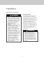
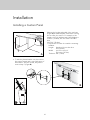
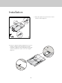
Installation Preparation
Steam will form inside the dishwasher during operation. At the end of the cycle, when the
dishwasher door is opened, it is required to use a steam protection foil to prevent any steam
from collecting on the underside of the counter top.
Steam Protection Foil
CAUTION
Steam protection foil must be applied
where the steam escapes when door is
first opened. Failure to install the
steam protection foil during
installation can lead to damage to to
the cabinets and countertop.
A
B
Fitting the Protection Foil
• Before applying the steam protection foil
to the underside of the countertop, clean
the area with a damp cloth (as shown in
Figure A). Once the area dries, apply the
steam protection foil.
• The steam protection foil will be applied
at the location where the hot steam
escapes when you first open the door (as
shown in Figure B).

14
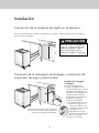
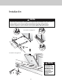
Installation
Now place the dishwasher into the opening and get ready to connect all hoses and electrical
connections.
Note that the marks on the
rubber connection hose should
be on the drain hose side.
Placement of Dishwasher into the Opening
Drain Hose Connection, Water Supply,
and Electrical Connections
CAUTION
Make sure all hoses are pulled
through the side opening of the
cabinet, no hoses are kinked, and
all slack is taken out as shown in
the figure to the left.
Drain Hose Connection
Connect the drain hose to the
drain plumbing.
• Use the supplied rubber
connection hose and drain
hose clamps to connect the
dishwasher drain hose to the
plumbing drain connection.
• Use the spring clamp to
secure the rubber
connection hose to the
dishwasher drain hose. Use
the screw clamp to secure
the rubber connection
hose to the plumbing
drain connection.

15
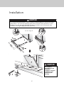
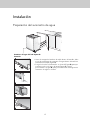
• Before pushing the dishwasher into the
cabinet, you must place water supply
hoses into the channel of the
dishwasher (Figure A).
• Place the supplied clips into the channel
(Figure B) so that you can move these
clips along the channel (Figure C) and
fix by pressing on (Figure D) so that you
can keep the water supply hose in the
channel.
Left Side Water Supply Connection
Installation
Preparation of Water Supply

16
Installation
• After installing one clip for each side,
push the dishwasher into the cabinet
(Figure E).
• Note that while pushing
the dishwasher into the
cabinet, water supply
hose must move in the
channel to the front
(Figure F).
• Fix the second clip
(Figure G).

17
Water supply may be connected to the
dishwasher in one of two ways:
• With metal braided hose.
• With copper tubing.
Installation
CAUTION
• Hot water supply line: Use minimum
3/8” O.D. copper tubing or metal
braided dishwasher supply line.
• Temperatures required for soldering
and sweating will damage the
dishwasher’s water inlet valve so if
any such operation is needed, keep
the heat source min. 7-7/8” (20.0cm)
away from the dishwasher’s water
inlet valve.
• There should not be any sharp bends
in the water line that may restrict the
water flow.
• Teflon tape or pipe thread compound
must be used for sealing the
connection. Before connecting the
copper water supply line to the
dishwasher, flush it with hot water to
clear any foreign material.
NOTICE
After connections are made, turn on the
water supply to check for leaks.

18
Installation
Electrical Connection
WARNING
• Make sure the voltage and frequency
listed on the data plate correspond
with the household electrical supply.
This data must correspond to prevent
injury and machine damage. Consult
a qualified electrician if in doubt.
• Only connect the dishwasher to the
mains when all installation and
plumbing work is done.
• DO NOT use any extension cord or
portable outlet device to connect the
dishwasher to a power supply.
• The power-supply receptacle for the
appliance shall be installed in a
cabinet or on a wall adjacent to the
undercounter space in which the
appliance is to be installed.
• The access hole of the supply cord to
the installation compartment must be
smooth and rounded and it must be
large enough for the attachment plug
to pass through. The longest
dimension of the opening shall not be
more than 1.5” (35mm). If the
partition is metal, it needs to be
covered with an edge protector.
• Care must be taken when the
appliance is installed or removed, to
reduce the likelihood of damage to
the power-supply cord.
WARNING
• Improper connection of the
equipment-grounding conductor can
result in a risk of electric shock.
Check with a qualified electrician or
service representative if you are in
doubt whether the appliance is
properly grounded. Do not modify
the plug provided with the appliance;
if it will not fit the outlet, have a
proper outlet installed by a qualified
electrician.
Grounding Instructions
This appliance must be grounded. In the
event of a malfunction or breakdown,
grounding will reduce the risk of electrical
shock by providing a path of least resistance
for electrical current. This appliance is
equipped with a cord having an equipment-
grounding conductor and a grounding plug.
The plug must be plugged into an
appropriate outlet that is installed and
grounded in accordance with all local codes
and ordinances. This appliance must be
connected to a grounded metal, permanent
wiring system, or an equipment-grounding
conductor must be run with the circuit
conductors and connected to the
equipment-grounding terminal or lead on
the appliance.

19
Installation
Readjusting Leveling Legs
Adjusting the Movable
Kickplate
Now that you have successfully
installed the dishwasher, you
need to attach the kickplate to
the dishwasher. The two-piece
kickplate can be adjusted to the
height and depth needed for
your kitchen. Be sure to use the
slotted kickplate in the front and
the other behind it. They slide
into each other.
1. Insert the movable kickplate
brackets into the channel (A).
2. Make sure that the plastic tab
to the left of the “L” opening
on the dishwasher has not
closed the channel you will
push the bracket through.
3. Now attach the kickplate to
the bracket with the two
(Ø 3/16”x1/4”-Ø 4mmx6mm)
screws and the caps provided
as follows.
Now that the dishwasher is in the cabinet,
you must readjust the leveling legs to bring
the dishwasher up to the required height
and attach it underneath the countertop.
• Readjust the front leveling leg with
adjusting wrench to balance the
dishwasher and raise it up under the
countertop; make sure the unit is level.
• Readjust the rear leveling leg with a
screwdriver to balance the dishwasher
and raise it to the required height using
the brackets supplied.
• Attach the dishwasher underneath the
countertop with the four screws supplied
(Ø 1/8”x1/8”-Ø 3.5mmx14mm). Make
sure you do not go through the top of the
countertop or damage granite.
A
B
C
NOTICE
There is a left and a right
bracket.
• Adjust the kickplate
brackets forward or
backwards so that they will
align with the kitchen
kickplate (B).
• Lock the kickplate
brackets as shown with the
plastic tab on the
dishwasher into the teeth
of the bracket (C).

20
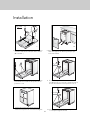
Installation
If the enclosure height is below 33-1/16”
(84.0cm), use only (o) labeled kickplate
(kickplate without slots). Installation should
be done following the steps illustrated in the
Figures A, B, and C respectively.
1. Bend tabs on kickplate (o) inwards (A).
2. Secure kickplate to brackets with screws (t)
as shown in the supply bags (B).
3. Attach caps (s) as shown in the supply
bags (C).
If the enclosure height is above 33-1/16”
(84.0cm), use “o” and “p” labeled kickplates
together. Make sure the slotted kickplate (p)
is on the outside so you can adjust height of
the kickplate. Installation should be done
following the steps illustrated in the figures
A, B, and C respectively.
1. Align the kickplate (o) and (p) (A).
2. Secure kickplates to brackets with screws
(t) after adjusting the height of the slotted
kickplate (p) (B).
3. Attach caps (s) as shown in the supply
bags (C).
B
s
t
C
A
o
A
s
t
C
B
o
p
La page est en cours de chargement...
La page est en cours de chargement...
La page est en cours de chargement...
La page est en cours de chargement...
La page est en cours de chargement...
La page est en cours de chargement...
La page est en cours de chargement...
La page est en cours de chargement...
La page est en cours de chargement...
La page est en cours de chargement...
La page est en cours de chargement...
La page est en cours de chargement...
La page est en cours de chargement...
La page est en cours de chargement...
La page est en cours de chargement...
La page est en cours de chargement...
La page est en cours de chargement...
La page est en cours de chargement...
La page est en cours de chargement...
La page est en cours de chargement...
La page est en cours de chargement...
La page est en cours de chargement...
La page est en cours de chargement...
La page est en cours de chargement...
La page est en cours de chargement...
La page est en cours de chargement...
La page est en cours de chargement...
La page est en cours de chargement...
La page est en cours de chargement...
La page est en cours de chargement...
La page est en cours de chargement...
La page est en cours de chargement...
La page est en cours de chargement...
La page est en cours de chargement...
La page est en cours de chargement...
La page est en cours de chargement...
La page est en cours de chargement...
La page est en cours de chargement...
La page est en cours de chargement...
La page est en cours de chargement...
La page est en cours de chargement...
La page est en cours de chargement...
La page est en cours de chargement...
La page est en cours de chargement...
La page est en cours de chargement...
La page est en cours de chargement...
La page est en cours de chargement...
La page est en cours de chargement...
La page est en cours de chargement...
La page est en cours de chargement...
La page est en cours de chargement...
La page est en cours de chargement...
La page est en cours de chargement...
La page est en cours de chargement...
La page est en cours de chargement...
La page est en cours de chargement...
La page est en cours de chargement...
La page est en cours de chargement...
La page est en cours de chargement...
La page est en cours de chargement...
La page est en cours de chargement...
La page est en cours de chargement...
La page est en cours de chargement...
La page est en cours de chargement...
-
 1
1
-
 2
2
-
 3
3
-
 4
4
-
 5
5
-
 6
6
-
 7
7
-
 8
8
-
 9
9
-
 10
10
-
 11
11
-
 12
12
-
 13
13
-
 14
14
-
 15
15
-
 16
16
-
 17
17
-
 18
18
-
 19
19
-
 20
20
-
 21
21
-
 22
22
-
 23
23
-
 24
24
-
 25
25
-
 26
26
-
 27
27
-
 28
28
-
 29
29
-
 30
30
-
 31
31
-
 32
32
-
 33
33
-
 34
34
-
 35
35
-
 36
36
-
 37
37
-
 38
38
-
 39
39
-
 40
40
-
 41
41
-
 42
42
-
 43
43
-
 44
44
-
 45
45
-
 46
46
-
 47
47
-
 48
48
-
 49
49
-
 50
50
-
 51
51
-
 52
52
-
 53
53
-
 54
54
-
 55
55
-
 56
56
-
 57
57
-
 58
58
-
 59
59
-
 60
60
-
 61
61
-
 62
62
-
 63
63
-
 64
64
-
 65
65
-
 66
66
-
 67
67
-
 68
68
-
 69
69
-
 70
70
-
 71
71
-
 72
72
-
 73
73
-
 74
74
-
 75
75
-
 76
76
-
 77
77
-
 78
78
-
 79
79
-
 80
80
-
 81
81
-
 82
82
-
 83
83
-
 84
84


AGA AELTTDW-BLK Le manuel du propriétaire
- Catégorie
- Lave-vaisselle
- Taper
- Le manuel du propriétaire
dans d''autres langues
- English: AGA AELTTDW-BLK Owner's manual
- español: AGA AELTTDW-BLK El manual del propietario
- português: AGA AELTTDW-BLK Manual do proprietário
Documents connexes
Autres documents
-
Viking MPDDP524SS Guide d'installation
-
Viking Range PDDP524 Guide d'installation
-
Summit DW186NTADA Le manuel du propriétaire
-
Appliances Connection Picks FFBD1831UW Guide d'installation
-
Frigidaire 1081977 Guide d'installation
-
IKEA VILLKORLIG Dishwasher Manuel utilisateur
-
Bertazzoni DW24S3IPV Manuel utilisateur
-
-
Dacor DDW24M999US Guide d'installation
-
Samsung DDW24M999US Guide d'installation