
467 772_a I 05/2012
057
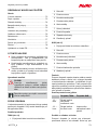
SUB 10000-13000 DS / TWIN 11000-14000
Betriebsanleitung

D
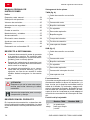
2 SUB 10000-13000 DS / TWIN 11000-14000
D ...
...............................................7
EN ................................................14
NL ................................................20
FR ................................................27
ES ................................................34
IT ................................................41
SL ................................................48
HR ................................................54
PL ................................................60
CS ................................................67
SK ................................................73
DA ................................................79
SV ................................................85
NO ................................................91
FI ................................................97
ET ..............................................103
LT ..............................................109
LV ..............................................115
HU ..............................................122
TR ..............................................129
RU ..............................................135
UK ..............................................142
© 2012
AL-KO KOBER GROUP Kötz, Germany
This documentation or excerpts therefrom may not be reproduced or disclosed to third parties without
the express permission of the AL-KO KOBER GROUP.

467 772_a 3
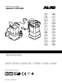
A
B
C
D
6
8
10
4
7
5
9
2
1
3
2
4
3
5
6
7
1
8
min. 300 x 300 mm
ca. 150 - 220 mm
Start
Stop
SUB 13000
TWIN 14000
min. 450 x 450 mm
min. 450 mm
Start
Stop

D
4 SUB 10000-13000 DS / TWIN 11000-14000
O
O
U
U
2
2
6
8
7
ON
ON
ON
OFF
F
G
E TWIN
SUB
1
2
1
1

467 772_a 5
J
H
I
2
1
4
3
MAN
MAX
MIN
1
MAN
MAX
MIN
MAN
Max
Min
9
8
7
6
5
4
3
2
1
0
4
2
0
6
2
0
2
2
0
0
2
0
8
1
0
4
1
0
6
1
0
2
1
0
0
1
0
8
0
6
0
4
0
2
6
,
5
1
4
,
4
1
2
,
3
1
8
,
0
1
4
,
8
6
,
9
2
,
7
6
8
,
4
6
,
3
4
,
2
2
,
1
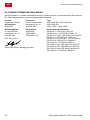
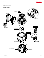
12
m3/h
l/min/1
9
8
7
6
5
4
3
2
1
2
0
4
0
6
0
8
0
10
0
12
0
160
0
4
2
0
6
2
0
2
2
0
0
2
0
8
1
0
4
1
6
,
5
1
4
,
4
1
2
,
3
1
8
,
0
1
4
,
8
6
,
9
2
,
7
6
8
,
4
6
,
3
4
,
2
2
,
1
12
m3/h
l/min/1
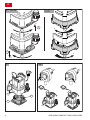
TWIN
10000
TWIN 14000
SUB 12000 DS
SUB 10000 DS
SUB 13000 DS

D
6 SUB 10000-13000 DS / TWIN 11000-14000
SUB 10000 DS (Art.Nr. 112 823)
SUB 12000 DS (Art.Nr. 112 824)
SUB 13000 DS (Art.Nr. 112 829)
(Klarwasser)
TWIN 11000 (Art.Nr. 112 830)
TWIN 14000 (Art.Nr. 112 831)
(Klar-/Schmutzwasser)
SUB 10000 DS 450 W
SUB 12000 DS 550 W
SUB 13000 DS 650 W
TWIN 11000 750 W
TWIN 14000 950 W
230 V AC/50 Hz 230 V AC/50 Hz
X 8 X 8
5 m 5 m
SUB 10000 DS 7 m
SUB 12000 DS 8 m
SUB 13000 DS 8 m
TWIN 11000 10 m
TWIN 14000 10 m
SUB 10000 DS 8000 l/h
SUB 12000 DS 9500 l/h
SUB 13000 DS 10500 l/h
TWIN 11000 13500 l/h
TWIN 14000 15000 l/h
35 °C 35 °C
2,5 cm
TWIN 11000 5,0 cm
TWIN 14000 6,0 cm
30 mm
TWIN 11000 20 mm
TWIN 14000 30 mm
SUB 10000 DS 5,5 kg
SUB 12000 DS 5,8 kg
SUB 13000 DS 6,0 kg
TWIN 11000 7,2 kg
TWIN 14000 8,4 kg
3 mm 8 mm
SUB 10000 DS cm: 37/15 - 39/17
SUB 12000 DS cm: 37/15 - 39/17
SUB 13000 DS cm:
13,5-21,5/11,5 - 15,5-23,5/13,5
TWIN 11000 cm: 41/22 - 46/27
TWIN 14000 cm:
17,0-25,0/15,0 - 21,3-29,3/19,3
10 m 10 m

Original-Betriebsanleitung
467 772_a 7
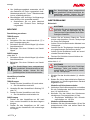
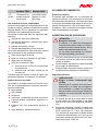
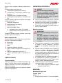
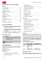
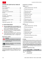
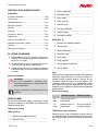
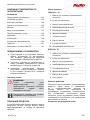
ORIGINAL-BETRIEBSANLEITUNG
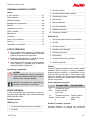
Inhaltsverzeichnis
Zu diesem Handbuch.........................................7
Produktbeschreibung..........................................7
Lieferumfang.......................................................8
Sicherheitshinweise............................................8
Montage..............................................................9
Inbetriebnahme...................................................9
Wartung und Pflege......................................... 10
Lagerung.......................................................... 11
Entsorgung....................................................... 11
Hilfe bei Störungen.......................................... 11
Garantie............................................................12
EG-Konformitätserklärung................................13
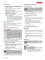
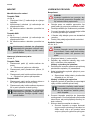
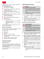
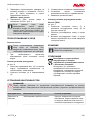
ZU DIESEM HANDBUCH
Lesen Sie diese Dokumentation vor der Inbe-
triebnahme durch. Dies ist Voraussetzung für
sicheres Arbeiten und störungsfreie Handha-
bung.
Beachten Sie die Sicherheits- und Warnhin-
weise in dieser Dokumentation und auf dem
Produkt.
Diese Dokumentation ist permanenter Be-
standteil des beschriebenen Produkts und
soll bei Veräußerung dem Käufer mit überge-
ben werden.
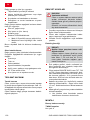
Zeichenerklärung
ACHTUNG!
Genaues Befolgen dieser Warnhinweise
kann Personen- und / oder Sachschäden
vermeiden.
ADVICE
Spezielle Hinweise zur besseren Ver-
ständlichkeit und Handhabung.
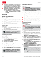
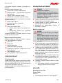
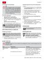
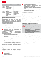
PRODUKTBESCHREIBUNG
In dieser Dokumentation werden verschiedene
Modelle von Tauchpumpen beschrieben. Identifi-
zieren Sie Ihr Modell anhand des Typschilds.
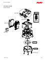
Produktübersicht
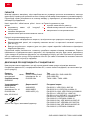
TWIN (Abb. A)
1 Anschlusskabel mit Netzstecker
2 Tragegriff
3 Motorgehäuse
4 Kombinippel
5 Verstellfuss
6 Ansaugschlitze
7 Winkelnippel
8 Pumpengehäuse
9 Rastschrauben
10 Schwimmerschalter
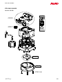
SUB (Abb. C)
1 Anschlusskabel mit Netzstecker
2 Tragegriff
3 Motorgehäuse
4 Kombi-Nippel
5 Verstellfuss
6 Ansaugschlitze
7 Gehäuse Niveauschalter
8 Niveauschalter
Funktion
Die Tauchpumpe saugt das Fördermedium durch
die Ansaugschlitze direkt an und fördert es zum
Pumpenausgang am Kombi-Nippel am Pumpen-
ausgang. Sie wird durch einen Schwimmerschal-
ter ein- und ausgeschaltet. Der Schaltweg des
Schimmerschalters kann durch Verstellen der Ka-
bellänge am Schwimmerschalter oder durch Ver-
stellen des Niveauschalters am Gehäuse ange-
passt werden.
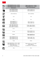
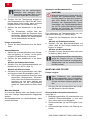
Stellung Verstellfuss
TWIN-Pumpen SUB-Pumpen
„U“ -
unten
Klar- oder
Schmutzwasser
kann gefördert
werden

D
Produktbeschreibung
8 SUB 10000-13000 DS / TWIN 11000-14000
TWIN-Pumpen SUB-Pumpen
„O“ -
oben
nur Klarwasser
kann gefördert
werden
Wasser kann
sehr flach abge-
saugt werden
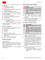
Bestimmungsgemäße Verwendung
Die Tauchpumpe ist für die private Nutzung in
Haus und Garten bestimmt. Sie darf nur im Rah-
men der Einsatzgrenzen gemäß der technischen
Daten betrieben werden.
Die Tauchpumpe eignet sich für die:
Entwässern bei Überschwemmungen
Um- und Auspumpen von Behältern (z. B.
Schwimmbecken)
Wasserentnahme aus Brunnen und Schäch-
ten
Entwässern von Drainagen und Sicker-
schächten.
Die Tauchpumpe ist ausschließlich zum Fördern
von folgenden Flüssigkeiten geeignet:
Klarwasser, Regenwasser
chlorhaltigem Wasser (z. B. Schwimmbe-
cken)
Brauchwasser
Nur bei TWIN-Modellen:
➯
Schmutzwasser mit max. 5 % Schweb-
stoffanteil
➯
Maximale Korngröße: siehe Technische
Daten
Eine andere oder darüber hinausgehende Ver-
wendung gilt als nicht bestimmungsgemäß.
Möglicher Fehlgebrauch
Die Tauchpumpe darf nicht im Dauerbetrieb ein-
gesetztwerden. Sie sind nicht geeignet zur Förde-
rung von:
Trinkwasser
Salzwasser
Lebensmitteln
aggressiven Medien, Chemikalien
ätzenden, brennbaren, explosiven oder ga-
senden Flüssigkeiten
Flüssigkeiten, die wärmer als 35 °C sind
sandhaltigem Wasser und schmirgelnden
Flüssigkeiten.
LIEFERUMFANG
Thermoschutz
Das Gerät ist mit einem Thermoschutzschalter
ausgestattet, der den Motor bei Überhitzung ab-
schaltet. Nach einer Abkühlphase von ca. 15 -
20 Minuten schaltet die Pumpe selbsttätig wieder
ein.
Betreiben Sie das Gerät nur, wenn die Tauch-
pumpe vollkommen eingetaucht ist.
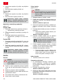
SICHERHEITSHINWEISE
ACHTUNG!
Verletzungsgefahr!
Gerät und Verlängerungskabel nur in
technisch einwandfreiem Zustand be-
nutzen! Beschädigte Geräte dürfen nicht
betrieben werden.
Sicherheits- und Schutzeinrichtungen
dürfen nicht außer Kraft gesetzt werden!
Kinder oder Personen, die die Betriebsanlei-
tung nicht kennen, dürfen das Gerät nicht be-
nutzen.
Das Gerät nie am Anschlusskabel hochhe-
ben, transportieren oder befestigen.
Eigenmächtige Veränderungen oder Umbau-
ten am Gerät sind verboten.
Elektrische Sicherheit
VORSICHT!
Gefahr beim Berühren spannungs-
führender Teile!
Stecker sofort vom Netz trennen,
wenn das Verlängerungskabel beschä-
digt oder durchtrennt wurde! Wir emp-
fehlen den Anschluss über einen FI-
Schutzschalter mit einem Nennfehler-
strom < 30 mA.
Die Haus-Netzspannung muss mit den An-
gaben zur Netzspannung in den Technischen
Daten übereinstimmen, keine andere Versor-
gungsspannung verwenden.
Das Gerät darf nur an einer elektrischen Ein-
richtung gemäß DIN/VDE 0100, Teil 737, 738
und 702 (Schwimmbäder) betrieben werden.
Zur Absicherung muss ein Leitungs-Schutz-
schalter 10 A sowie ein Fehlerstrom-Schutz-
schalter mit einem Nennfehlerstrom von
10/30 mA installiert werden.

Montage
467 772_a 9
Nur Verlängerungskabel verwenden, die für
den Gebrauch im Freien vorgesehen sind -
Mindestquerschnitt 1,5 mm
2
. Kabeltrommeln
immer vollständig abrollen.
Beschädigte oder brüchige Verlängerungs-
kabel dürfen nicht verwendet werden.
➯
Kontrollieren Sie vor jeder Inbetrieb-
nahme den Zustand ihres Verlänge-
rungskabels.
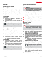
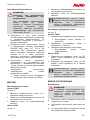
MONTAGE
Druckleitung montieren
TWIN-Pumpen
siehe Abb. A
1. Schrauben Sie den Anschlusswinkel (7) in
den Pumpenausgang ein.
2. Schrauben Sie den Kombi-Nippel (4) auf den
Anschlusswinkel.
3. Befestigen Sie einen Schlauch am Kombi-
Nippel.
SUB-Pumpen
siehe Abb. C
1. Schrauben Sie den Kombi-Nippel (4) auf den
Anschlusswinkel.
2. Befestigen Sie einen Schlauch am Kombi-
Nippel.
ADVICE
Der Kombi-Nippel kann entsprechend
dem gewählten Schlauchanschluss ab-
geschnitten werden. Nutzen Sie den
größtmöglichen Schlauchdurchmesser.
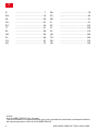
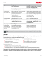
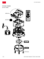
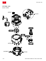
Verstellfuss einstellen
siehe Abb. E
TWIN-Pumpen
1. Drehen Sie den Verstellfuss (6) nach rechts.
➯
Der Verstellfuss rastet aus.
2. Verstellen Sie den Verstellfuss in Stellung "O"
oder "U".
3. Drehen Sie den Verstellfuss nach links.
➯
Der Verstellfuss rastet wieder ein.
SUB-Pumpen
1. Drehen Sie den Verstellfuss um 90° nach
links, um den Verstellfuß in die obere Lage zu
bringen.
2. Drehen Sie den Verstellfuss um 90° nach
rechts, um den Verstellfuß in die untere Lage
zu bringen.
ADVICE
Der Kombi-Nippel kann entsprechend
dem gewählten Schlauchanschluss ab-
geschnitten werden. Nutzen Sie den
größtmöglichen Schlauchdurchmesser.
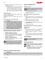
INBETRIEBNAHME
Sicherheit
ACHTUNG!
Schließen Sie durch geeignete Maßnah-
men aus, dass bei Störungen an der
Tauchpumpe Folgeschäden durch Über-
flutungen entstehen.
Achten Sie auf sicheren Stand der Tauch-
pumpe oder betreiben Sie die Tauchpumpe
an einem Seil hängend.
Achten Sie auf ausreichenden Abstand zum
Untergrund.
Lassen Sie die Tauchpumpe niemals gegen
eine geschlossene Druckleitung laufen.
Achten Sie bei Schächten immer auf ausrei-
chende Dimensionierung.
Decken Sie Schächte immer trittsicher ab.
Pumpe einschalten
siehe Abb. A - C
ACHTUNG!
Die Tauchpumpe darf keine Festkörper
ansaugen. Sand und andere schmir-
gelnde Stoffe im Fördermedium zerstö-
ren die Tauchpumpe.
1. Wickeln Sie das Anschlusskabel (1) vollstän-
dig ab.
2. Stellen Sie sicher, dass elektrische Steckver-
bindungen im überflutungssicheren Bereich
angebracht sind.
Modelle mit Schwimmerschalter
3. Verändern Sie die Klemmposition und stellen
Sie die Schaltpunkte des Schwimmerschal-
ters (10) individuell ein.
4. Klemmen Sie das Kabel des Schwimmer-
schalters am Pumpengehäuse (4) fest.
➯
Empfohlene Kabellänge des Schwim-
merschalters ca. 100 mm.
Modelle mit Niveauschalter
5. Schieben Sie den Niveauschalter (8) auf die
entsprechende Höhe und stellen damit die
Schaltpunkte ein.

D
Inbetriebnahme
10 SUB 10000-13000 DS / TWIN 11000-14000
ADVICE
Benutzen sie bei schlammigem,
sandigem oder steinigem Unter-
grund eine geeignete Platte für den
sicheren Stand der Tauchpumpe.
6. Tauchen Sie die Tauchpumpe langsam in
das Fördermedium ein. Halten Sie die Tauch-
pumpe dabei leicht schräg, damit eventuell
eingeschlossene Luft entweichen kann.
7. Stecken Sie den Netzstecker in die Steck-
dose.
➯
Die Tauchpumpe schaltet über den
Schwimmerschalter bei Erreichen eines
bestimmten Wasserstands automatisch
ein und bei Abfallen des Wasserstands
auf die Abschalthöhe wieder ab.
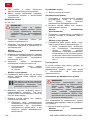
Pumpe ausschalten
1 Ziehen Sie den Netzstecker aus der Steck-
dose.
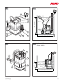
Automatikbetrieb
1. Stellen Sie im Automatikbetrieb den Verstell-
fuss auf Stellung „U“ (Unten), um die größt-
mögliche Förderleistung zu erreichen.
2. Stecken Sie den Netzstecker in die Steck-
dose.
Modelle mit Schwimmerschalter
3. Schalten Sie den Betriebswahlschalter am
Netzstecker auf „AUTO“ (Abb. G).
Modelle mit Niveauschalter
4. Schieben Sie den Niveauschalter nach oben
auf die gewünschte Einschalthöhe (Abb. I).
➯
Die Pumpen schaltet bei Erreichen eines
bestimmten Wasserstands (Einschalt-
höhe) durch den Schwimmerschalter au-
tomatisch ein und beim Abfallen des
Wasserstands auf die Ausschalthöhe
wieder ab, siehe technische Daten Seite
5.
Manueller Betrieb
Im manuellen Betrieb kann das Wasser bis auf
eine sehr niedrige Restwasserhöhe abgepumpt
werden.
Mindestwasserstand zur Inbetriebnahme: siehe
technische Daten.
Abpumpen auf Restwasserhöhe
ACHTUNG!
Beaufsichtigen Sie die Pumpe beim Ab-
pumpen auf Restwasserhöhe ständig
und vermeiden Sie, dass die Pumpe tro-
cken läuft. Setzen Sie die Pumpe bei
Erreichen der Restwasserhöhe durch
Umschalten des Betriebswahlschalters
auf „AUTO“ außer Betrieb.Die Pumpen
schalten bei Erreichen der Einschalt-
höhe automatisch wieder ein.
Zum Abpumpen auf Restwasserhöhe den Ver-
stellfuss auf Stellung „O“ (Oben) stellen:
1. Ziehen Sie den Netzstecker aus der Steck-
dose.
Modelle mit Schwimmerschalter
2. Schalten Sie den Betriebswahlschalte auf
„MAN“ (Abb. G). Die Pumpe schaltet ein und
beginnt zu fördern.
Modelle mit Niveauschalter
3. Schieben Sie den Niveauschalter nach oben
in Stellung „MAN“ (Abb. I)
ADVICE
Wird die Restwasserhöhe unterschritten,
saugt die Pumpe Luft an. In diesem
Fall muss die Pumpe bei ansteigendem
Wasserstand und vor erneutem Betrieb
entlüftet werden.
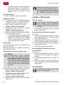
WARTUNG UND PFLEGE
Pumpe reinigen
ADVICE
Nach Förderung von chlorhaltigem
Schwimmbadwasser oder Flüssigkeiten,
die Rückstände hinterlassen, muss die
Pumpe mit klarem Wasser gespült wer-
den.
1. Reinigen Sie die Ansaugschlitze des Saugfu-
ßes bei Bedarf mit klarem Wasser.
Niveauschalter demontieren/montieren
siehe Abb. H
1. Befestigungsschraube (2) ausschrauben und
Gehäuse Schwimmerschalter (1) erst nach
oben, dann nach vorne abklappen.
2. Schwimmerkörper (4) und Führungen (3) rei-
nigen.
3. Schwimmerkörper wieder in die Führung ein-
setzen.

Wartung und Pflege
467 772_a 11
4. Gehäuse Schwimmerschalter wieder einset-
zen und nach unten drücken.
5. Befestigungsschraube einschrauben.
Verstellfuss demontieren/montieren
TWIN-Pumpen
siehe Abb. F
1. Rastschrauben (7) ausschrauben und den
Verstellfuss (6) aus dem Pumpengehäuse (8)
herausziehen.
2. Verstellfuss und Pumpengehäuse reinigen.
3. Verstellfuss in Pumpengehäuse einsetzen,
ausrichten und Rastschrauben wieder ein-
schrauben.
LAGERUNG
ADVICE
Bei Frostgefahr muss das System voll-
ständig entleert werden.
ENTSORGUNG
Ausgediente Geräte, Batterien oder
Akkus nicht über den Hausmüll ent-
sorgen!
Verpackung, Gerät und Zubehör sind aus
recyclingfähigen Materialien hergestellt
und entsprechend zu entsorgen.
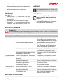
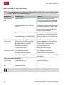
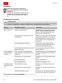
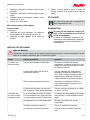
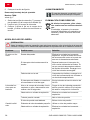
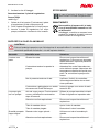
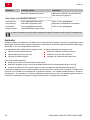
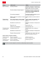
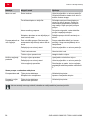
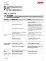
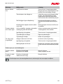
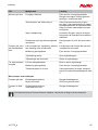
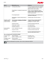
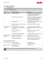
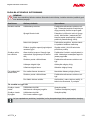
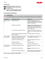
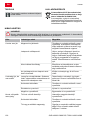
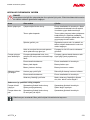
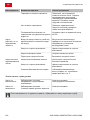
HILFE BEI STÖRUNGEN
VORSICHT!
Vor allen Arbeiten zur Störungsbeseitigung den Netzstecker ziehen. Fehler in der elektrischen
Anlage durch eine Elektrofachkraft beseitigen lassen.
Störung Mögliche Ursache Lösung
Laufrad blockiert. Schmutz im Ansaugbereich entfernen.
Durch Öffnung im Motorgehäuse hin-
ten mit geeignetem Werkzeug reinigen.
Thermoschalter hat abgeschaltet. Warten, bis der Thermoschalter die
Pumpe wieder einschaltet. Auf maxi-
male Temperatur des Fördermediums
achten. Tauchpumpe prüfen lassen.
Keine Netzspannung vorhanden. Sicherungen prüfen, Stromversorgung
von Elektrofachkraft prüfen lassen.
Motor läuft nicht.
Schwimmerschalter schaltet nicht bei
ansteigendem Wasserstand.
Pumpe an eine AL-KO Servicestelle
schicken.
Luft im Pumpengehäuse. rockenlauf,
automatische Abschaltung nach 90
Sekunden
Pumpe durch Schräghalten entlüften.
Verstellfuss falsch eingestellt.
Saugseitige Verstopfung. Schmutz im Ansaugbereich entfernen.
Druckleitung geschlossen. Druckleitung öffnen.
Pumpe läuft, aber
fördert nicht.
Druckschlauch geknickt. Druckschlauch strecken.
Schlauchdurchmesser zu klein. Größeren Druckschlauch verwenden.
Saugseitige Verstopfung. Schmutz im Ansaugbereich entfernen.
Fördermenge zu
gering
Förderhöhe zu groß. Max. Förderhöhe beachten, siehe
technische Daten Seite 5.
Nur Pumpen mit Niveauschalter

D
Garantie
12 SUB 10000-13000 DS / TWIN 11000-14000
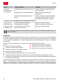
Störung Mögliche Ursache Lösung
Pumpe läuft im-
mer.
Schwimmkörper blockiert.
Schalter falsch eingestellt.
Schwimmkörper reinigen.
Schalter korrekt einstellen.
Pumpe ist immer
aus.
Schwimmkörper blockiert.
Wasserstand zu niedrig
Schwimmkörper reinigen.
ADVICE
Bei nicht behebbaren Störungen wenden Sie sich bitte an unseren zuständigen Kundendienst.
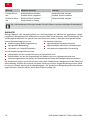
GARANTIE
Etwaige Material- oder Herstellungsfehler am Gerät beseitigen wir während der gesetzlichen Verjäh-
rungsfrist für Mängelansprüche entsprechend unserer Wahl durch Reparatur oder Ersatzlieferung. Die
Verjährungsfrist bestimmt sich jeweils nach dem Recht des Landes, in dem das Gerät gekauft wurde.
Unsere Garantiezusage gilt nur bei:
beachten dieser Bedienungsanleitung
sachgemäßer Behandlung
verwenden von Original-Ersatzteilen
Die Garantie erlischt bei:
eigenmächtigen Reparaturversuchen
eigenmächtigen technischen Veränderungen
nicht bestimmungsgemäßer Verwendung
Von der Garantie ausgeschlossen sind:
Lackschäden, die auf normale Abnutzung zurückzuführen sind
Verschleißteile, die auf der Ersatzteilkarte mit Rahmen [xxx xxx (x)] gekennzeichnet sind
Verbrennungsmotoren (hier gelten die Garantiebestimmungen der jeweiligen Motorenhersteller)
Die Garantiezeit beginnt mit dem Kauf durch den ersten Endabnehmer. Maßgebend ist das Datum auf
dem Kaufbeleg. Wenden Sie sich bitte mit dieser Erklärung und dem Original-Kaufbeleg an Ihren Händ-
ler oder die nächste autorisierte Kundendienststelle. Die gesetzlichen Mängelansprüche des Käufers
gegenüber dem Verkäufer bleiben durch diese Erklärung unberührt.

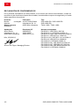
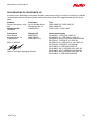
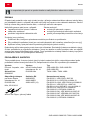
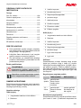
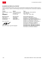
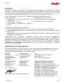
EG-Konformitätserklärung
467 772_a 13
EG-KONFORMITÄTSERKLÄRUNG
Hiermit erklären wir, dass dieses Produkt in der von uns in Verkehr gebrachten Ausführung, den Anfor-
derungen der harmonisierten EU-Richtlinien, EU-Sicherheitsstandards und den produktspezifischen
Standards entspricht.
Produkt Hersteller Typ
Tauchpumpe, elektrisch
Seriennummer
G3023025
AL-KO Geräte GmbH
Ichenhauser Str. 14
D-89359 Kötz
SUB 10000 DS / SUB 12000
DS SUB 13000 DS
TWIN 11000 / TWIN 14000
Bevollmächtigter EU-Richtlinien Harmonisierte Normen
Hr. Anton Eberle
Ichenhauser Str. 14
D-89359 Kötz
2006/95/EU
2004/108/EU
2000/14/EU (13)
2011/65/EU
Kötz, 25.05.2012
Antonio De Filippo; Managing Director
EN 60335-1; VDE 0700-1:2007-02
EN 60335-2-41; VDE 0700-41:2004-12
EN 60335-2-41/A2; VDE 0700-41/A2:2009-02
EN 55014-1; VDE 0875-14-1:2007-06
EN 55014-1/A1; VDE 0875-14-1/A1:2008-12
EN 55014-2; VDE 0875-14-2:2009-06
EN 61000-3-2; VDE 0838-2:2006-10
EN 61000-3-2/A1; VDE 0838-2/A1:2007-05
EN 61000-3-2/A7; VDE0838-2/A7:2007-06
EN 61000-3-2/A4; VDE 0838-2/A4:2007-06
EN 61000-3-3; VDE 0838-3:2009-06

en
Original instructions for use
14 SUB 10000-13000 DS / TWIN 11000-14000
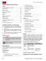
ORIGINAL INSTRUCTIONS FOR USE
Contents
About this handbook........................................ 14
Product description.......................................... 14
Scope of delivery............................................. 15
Safety instructions............................................15
Assembly..........................................................16
Startup..............................................................16
Maintenance and care..................................... 17
Storage.............................................................17
Disposal............................................................17
Help in case of malfunctions............................18
Warranty........................................................... 19
EU declaration of conformity............................19
ABOUT THIS HANDBOOK
Read this documentation before starting up
the machine. This is a precondition for safe
working and flawless operation.
Observe the safety warnings in this docu-
mentation and on the product.
This documentation is a permanent integral
part of the product described and must be
passed on to the new owner if the product is
sold.
Explanation of symbols
CAUTION!
Following these safety warnings care-
fully can prevent personal injury and/or
material damage.
ADVICE
Special instructions for greater ease of
understanding and improved handling.
PRODUCT DESCRIPTION
This documentation describes various different
models of immersion pumps. Identify your model
using the identification plate.
Product overview
TWIN (Fig. A)
1 Connection cable with mains plug
2 Carrying handle
3 Motor housing
4 Combination adapter
5 Adjustable foot
6 Suction slots
7 Elbow nipple
8 Pump housing
9 Engaging screws
10 Float switch
SUB (Fig. C)
1 Connection cable with mains plug
2 Carrying handle
3 Motor housing
4 Combination nipple
5 Adjustable foot
6 Suction slots
7 Level switch housing
8 Level switch
Function
The immersion pump draws the conveying me-
dium through the suction slots directly and feeds
it to the pump outlet at the combination nipple. It
is switched on and off using a float switch. The
switching movement of the float switch can be ad-
apted to suit by adjusting the cable length on the
float switch or by adjusting the level switch on the
housing.
Adjusting foot setting
TWIN pumps SUB pumps
"U" -
bottom
Clear and waste
water can be
conveyed.
"O" -
top
only clear water
can be conveyed
Water can be
drawn off very
flat

Product description
467 772_a 15
Designated use
The immersion pump is designed for private use
in the house and garden. It must only be operated
within the framework of the deployment limitations
in accordance with the technical data.
The immersion pump is suitable for:
Water removal in the event of a flood
Re-pumping and pumping out from vessesl
(e.g. swimming pools)
Water removal from streams and shafts
Water removal from drains and trickle shafts.
The immersion pump is only suitable for convey-
ing the following fluids:
Clear water, rainwater
Chlotine-containing water (e.g. swimming
pools)
Waste water
Only on TWIN models:
➯
Waste water with max. 5 % suspended
material
➯
Maximum grain size: see technical data
Any use not in accordance with this designated
use shall be regarded as misuse.
Possible misuse
The immersion pump must not be used conti-
nuously. They are not suitable for conveying:
Drinking water
Salt water
Foodstuffs
Aggressive media, chemicals
Corrosive, flammable, explosive or fuming
fluids
Fluids that are hotter than 35 °C
Water containing sand and abrasive fluids
SCOPE OF DELIVERY
Thermal protection
The unit is fitted with a thermal protection switch
which switches the motor off in the event of over-
heating. The pump switches on again automati-
cally after a cooling down period of approx. 15 -
20 minutes.
Operate the unit only if the immersion pump is fully
immersed.
SAFETY INSTRUCTIONS
CAUTION!
Danger of injury!
Only use the machine and the extension
cable if it is in perfect technical condition!
Damaged units must not be used.
Safety and protective devices must not
be deactivated!
Children, or people who are not familiar with
the operating instructions, are not allowed to
use the machine.
Never lift, transport or suspend the unit using
the connection cable.
Unilateral modifications or conversions of the
unit are prohibited.
Electrical safety
CAUTION!
Danger when touching voltage con-
ducting parts!
Disconnect the plug from the mains if the
extension cable is damaged or severed!
We recommend connecting a RCD (re-
sidual current operated device) having a
nominal residual current of < 30 mA.
The house mains voltage must agree with the
details quoted in the technical data, do not
use any other supply voltage.
The unit must only be operated with an
electrical installation in accordance with DIN/
VDE 0100, Part 737, 738 and 702 (swimming
pools). Protection must be provided by a 10 A
line protection switch and a RCCD (residual
current operated device) having a nominal re-
sidual current of 10/30 mA.
Use only extension cables that are suitable
for use outdoors - minimum cross-section 1.5
mm
2
. Cable drums should always be unrolled
completely.
Damaged or brittle extension cables must not
be used.
➯
Check the condition of your extension
cable each time you start to use the
equipment.

en
Assembly
16 SUB 10000-13000 DS / TWIN 11000-14000
ASSEMBLY
Mounting the pressure line
TWIN pumps
see Fig. A
1. Screw the connection elbow (7) into the pump
outlet.
2. Screw the combination nipple (4) onto the
connection elbow.
3. Fix a hose to the combination nipple.
SUB pumps
see Fig. C
1. Screw the combination nipple (4) onto the
connection elbow.
2. Fix a hose to the combination nipple.
ADVICE
The combination nipple can be trimmed
to suit the selected hose connection. Use
the largest possible hose diameter.
Setting the adjustable foot
see Fig. E
TWIN pumps
1. Turn the adjustable foot (6) to the right.
➯
The adjustable foot disengages.
2. Set the adjustable foot to position "O" or "U".
3. Turn the adjustable foot (6) to the left.
➯
The adjustable foot locks back in posi-
tion.
SUB pumps
1. Turn the adjustable foot 90° to the left to move
the adjustable foot to the top position.
2. Turn the adjustable foot 90° to the right to
move the adjustable foot to the bottom posi-
tion.
ADVICE
The combination nipple can be trimmed
to suit the selected hose connection. Use
the largest possible hose diameter.
STARTUP
Safety
CAUTION!
Exclude, by suitable means, that, in the
event of a fault in the immersion pump,
consequential damage is caused by floo-
ding.
Make sure that the immersion pump is stan-
ding securely or operate the immersion pump
suspended from a rope.
Make sure there is adequate clearance under
the pump.
Never allow the immersion pump to run
against a closed off pressure line.
When using in shafts, make sure the size is
adequate.
Always cover the shaft with a secure foot-
plate.
Switching the pump on
see Fig. A - C
CAUTION!
The immersion pump must not draw in
any solid bodies. Sand and other abra-
sive materials in the conveying medium
will destroy the immersion pump.
1. Unwind the connection cable (1) completely.
2. Make sure that the electrical plug connection
is mounted in the area safe from flooding.
Models with float switch
3. Change the terminal position and adjust the
switching points of the float switch(10) indivi-
dually.
4. Attach the cable on the float switch to the
pump housing(4)securely.
➯
Recommended cable length on the float
switch approx. 100 mm
Models with level switch
5. Slide the level switch (8) to the relevant height
and thus set the switching points.
ADVICE
Use a suitable plate to ensure se-
cure mounting of the immersion
pump on muddy, sandy or stony
ground.
6. Immerse the immersion pump in the convey-
ing medium slowly. Hold the immersion pump
at a slight angle to allow any air to escape.
7. Insert the mains plug into the plug socket.
➯
The immersion pump switches on auto-
matically using the float switch when a
specific water level has been reached,
and switches off again if the water drops
below the switch-off height.
Switching the pump off
1 Remove the mains plug from the plug socket.

Startup
467 772_a 17
Automatic mode
1. In automatic mode, set the adjustable foot to
position "U" (bottom) to achieve the greatest
possible feed rate.
2. Insert the mains plug into the plug socket.
Models with float switch
3. Switch the operation selection switch on the
mains switch to "AUTO" (Fig. G).
Models with level switch
4. Slide the level switch upwards to the desired
switch-on height (Fig. I).
➯
The pump switches on automatically at a
specific water level (switch-on height) by
the float switch and when the water level
falls to the switch-off height it switches off
again, see technical data Page 5
Manual operation mode
In manual mode, the water can be pumped away
to a very low level of residual water.
Minimum water level for commissioning: see tech-
nical data.
Pumping out to residual water level
CAUTION!
Monitor the pump continuously when
pumping out to the residual water level
and avoid the pump running dry. Shut
the pump down when the residual wa-
ter level has been reached by switching
the operation mode selector switch to
"AUTO". The pumps switch on again au-
tomatically when the switch-on height is
reached.
Set the adjustable foot to the "O" (top) position for
pumping out to the residual water level:
1. Remove the mains plug from the plug socket.
Models with float switch
2. Switch the operation selection switch on the
mains switch to "MAN" (Fig. G). The pump
switches on and starts to feed.
Models with level switch
3. Slide the level switch upwards to the "MAN"
position (Fig. I).
ADVICE
If the water drops below the residual wa-
ter level, the pump will draw air in. In this
case, the pump must be vented when
the water level rises and before using it
again.
MAINTENANCE AND CARE
Cleaning the pump
ADVICE
After conveying chlorine-containing
swimming pool water or fluids that leave
a residue, the pump must be flushed out
with clear water.
1. Clean the suction slots on the suction foot if
necessary with clear water.
Removing/fitting the level switch
see Fig. H
1. Unscrew the fixing screw(2) and then first tip
the housing float switch(1) upwards and then
tilt to the front.
2. Clean the float body (4) and guides (3).
3. Place the float body back in the guide.
4. Replace the housing float body and push
downwards.
5. Screw the fixing screw in.
Removing/fitting the adjustable foot
TWIN pumps
see Fig. F
1. Unscrew the engaging screws (7) and pull the
adjustable foot (6) out of the pump housing
(8).
2. Clean the adjustable foot and the pump hou-
sing.
3. Insert the adjustable foot in the pump housing,
align and screw the engaging screws back in
place.
STORAGE
ADVICE
In the event of a risk of frost, the system
must be drained completely.
DISPOSAL
Do not dispose of old
equipment,batteries or accumulators
as householdwaste!
Product, packaging, and accessories
were made with recyclable materials, and
should be disposed of accordingly.

en
Help in case of malfunctions
18 SUB 10000-13000 DS / TWIN 11000-14000
HELP IN CASE OF MALFUNCTIONS
CAUTION!
Disconnect the mains plug before any fault rectification work! Faults in the electrical system
must be rectified by a qualified electrician.
Malfunction Possible cause Solution
Impeller blocked. Remove dirt in the suction area.
Clean with a suitable tool through the
opening at the back of the motor hou-
sing.
Thermal protection switch has swit-
ched off.
Wait until the thermal protection switch
on the pump switches on again. Take
note of the maximum temperature of
the conveying medium. Have the im-
mersion pump inspected.
No mains power. Check the fuses, have the power sup-
ply checked by a qualified electrician.
Motor does not
run
Float switch does not switch off when
the water level rises.
Send the pump to an AL-KO service
facility.
Air in pump housing. Dry running. Au-
tomatic switch off after 90 seconds.
Vent the pump by holding it at an
angle. Adjustable foot set incorrectly.
Blockage on the suction side. Remove dirt in the suction area.
Pressure line closed off. Open the pressure line.
Pump running but
does not feed.
Pressure hose kinked. Extend the pressure hose.
Hose diameter too small. Use a bigger pressure hose.
Blockage on the suction side. Remove dirt in the suction area.
Feed rate too low
Feed head too high. Observe max. feed head, see technical
data Page 5.
Only pumps with level switch
Pump running
continuously.
Float body blocked
Switch set incorrectly.
Clean the float body.
Adjust the switch correctly.
Pump is always
off.
Float body blocked
Water level too low
Clean the float body.
ADVICE
If the faults cannot be rectified, please contact our customer service department.

Warranty
467 772_a 19
WARRANTY
If any material or manufacturing defects are found during the statutory customer protection period, we
will either repair or replace the equipment, whichever we consider the more appropriate. This statutory
period may vary according to the legislation in force in the country where the equipment was purchased.
Our warranty is valid only if:
The equipment has been used properly
The operating instructions have been followed
Genuine replacement parts have been used
The warranty is no longer valid if:
The equipment has been tampered with
Technical modifications have been made
The equipment was not used for its intended
purpose
The following are not covered by warranty:
Paint damage due to normal wear
Wear parts identified by a border [xxx xxx (x)] on the spare parts list
Combustion motors (these are covered by a separate warranty from the manufacturer concerned)
The warranty period begins on the purchase by the first end user. Decisive is the date on the receipt.
To make a claim under warranty, please take this statement of warranty and proof of purchase to the
nearest authorised customer service centre. This warranty does not affect the usual statutory rights of
the customer relative to the seller.
EU DECLARATION OF CONFORMITY
We hereby declare that this product, in the version brought into circulation by us, complies with the re-
quirements of the harmonised EU guidelines, EU safety standards and the product-specific standards.
Product Manufacturer Type
Immersion pump, electri-
cal
Serial number
G3023025
AL-KO Geräte GmbH
Ichenhauser Str. 14
D-89359 Kötz
SUB 10000 DS / SUB 12000 DS
SUB 13000 DS
TWIN 11000 / TWIN 14000
Duly authorised person EU guidelines Harmonised standards
Anton Eberle
Ichenhauser Str. 14
D-89359 Kötz
2006/95/EU
2004/108/EU
2000/14/EU (13)
Kötz, 25.05.2012
Antonio De Filippo; Managing Director
EN 60335-1; VDE 0700-1:2007-02
EN 60335-2-41; VDE 0700-41:2004-12
EN 60335-2-41/A2; VDE 0700-41/A2:2009-02
EN 55014-1; VDE 0875-14-1:2007-06
EN 55014-1/A1; VDE 0875-14-1/A1:2008-12
EN 55014-2; VDE 0875-14-2:2009-06
EN 61000-3-2; VDE 0838-2:2006-10
EN 61000-3-2/A1; VDE 0838-2/A1:2007-05
EN 61000-3-2/A7; VDE0838-2/A7:2007-06
EN 61000-3-2/A4; VDE 0838-2/A4:2007-06
EN 61000-3-3; VDE 0838-3:2009-06

nl
Gebruiksaanwijzing
20 SUB 10000-13000 DS / TWIN 11000-14000
GEBRUIKSAANWIJZING
Inhoudsopgave
Over dit handboek............................................20
Productbeschrijving.......................................... 20
Inhoud van de levering.................................... 21
Veiligheidsvoorschriften....................................21
Montage............................................................22
Inbedrijfstelling..................................................22
Onderhoud........................................................23
Opslag.............................................................. 23
Afvoeren........................................................... 24
Storingen oplossen.......................................... 24
Garantie............................................................25
EG-conformiteitsverklaring............................... 26
OVER DIT HANDBOEK
Lees deze documentatie vóór ingebruikname
door. Dit is een voorwaarde voor veilig wer-
ken en storingsvrij gebruik.
Neem de veiligheidsvoorschriften en waar-
schuwingen in deze documentatie en op het
product in acht.
Deze documentatie is permanent onderdeel
van het beschreven product en dient bij ver-
koop aan de koper te worden overgedragen.
Legenda
LET OP!
Het nauwkeurig in acht nemen van deze
waarschuwingen kan verwondingen en/
of materiële schade voorkomen.
ADVICE
Speciale aanwijzingen voor een beter
begrip en gebruik.
PRODUCTBESCHRIJVING
In deze documentatie worden diverse modellen
dompelpompen beschreven. U kunt uw model
identificeren aan de hand van het typeplaatje.
Productoverzicht
TWIN (Afb. A)
1 Aansluitkabel met lichtnetstekker
2 Draaggreep
3 Motorbehuizing
4 Combinippel
5 Verstelbare voet
6 Aanzuigsleuf
7 Elleboogstuk
8 Pomphuis
9 Borgschroeven
10 Vlotterschakelaar
SUB (Afb. C)
1 Aansluitkabel met lichtnetstekker
2 Draaggreep
3 Motorbehuizing
4 Combinippel
5 Verstelbare voet
6 Aanzuigsleuf
7 Behuizing niveauschakelaar
8 Niveauschakelaar
Werking
De dompelpomp zuigt de te verpompen vloeis-
tof rechtstreeks aan via de aanzuigsleuf en ver-
pompt deze via de pompuitgang naar de combi-
nippel. Het apparaat wordt via een vlotterscha-
kelaar in- en uitgeschakeld. De schakelweg van
de vlotterschakelaar kan worden aangepast door
de kabellengte te verstellen aan de vlotterscha-
kelaar of door de niveauschakelaar aan de behui-
zing te verstellen.
Stand van verstelbare voet
TWIN-pompen SUB-pompen
„U“ -
onder
verpompen van
zowel schoon als
vuil water
„O“ -
boven
alleen verpom-
pen van schoon
water
water kan zeer
vlak worden af-
gezogen
La page est en cours de chargement...
La page est en cours de chargement...
La page est en cours de chargement...
La page est en cours de chargement...
La page est en cours de chargement...
La page est en cours de chargement...
La page est en cours de chargement...
La page est en cours de chargement...
La page est en cours de chargement...
La page est en cours de chargement...
La page est en cours de chargement...
La page est en cours de chargement...
La page est en cours de chargement...
La page est en cours de chargement...
La page est en cours de chargement...
La page est en cours de chargement...
La page est en cours de chargement...
La page est en cours de chargement...
La page est en cours de chargement...
La page est en cours de chargement...
La page est en cours de chargement...
La page est en cours de chargement...
La page est en cours de chargement...
La page est en cours de chargement...
La page est en cours de chargement...
La page est en cours de chargement...
La page est en cours de chargement...
La page est en cours de chargement...
La page est en cours de chargement...
La page est en cours de chargement...
La page est en cours de chargement...
La page est en cours de chargement...
La page est en cours de chargement...
La page est en cours de chargement...
La page est en cours de chargement...
La page est en cours de chargement...
La page est en cours de chargement...
La page est en cours de chargement...
La page est en cours de chargement...
La page est en cours de chargement...
La page est en cours de chargement...
La page est en cours de chargement...
La page est en cours de chargement...
La page est en cours de chargement...
La page est en cours de chargement...
La page est en cours de chargement...
La page est en cours de chargement...
La page est en cours de chargement...
La page est en cours de chargement...
La page est en cours de chargement...
La page est en cours de chargement...
La page est en cours de chargement...
La page est en cours de chargement...
La page est en cours de chargement...
La page est en cours de chargement...
La page est en cours de chargement...
La page est en cours de chargement...
La page est en cours de chargement...
La page est en cours de chargement...
La page est en cours de chargement...
La page est en cours de chargement...
La page est en cours de chargement...
La page est en cours de chargement...
La page est en cours de chargement...
La page est en cours de chargement...
La page est en cours de chargement...
La page est en cours de chargement...
La page est en cours de chargement...
La page est en cours de chargement...
La page est en cours de chargement...
La page est en cours de chargement...
La page est en cours de chargement...
La page est en cours de chargement...
La page est en cours de chargement...
La page est en cours de chargement...
La page est en cours de chargement...
La page est en cours de chargement...
La page est en cours de chargement...
La page est en cours de chargement...
La page est en cours de chargement...
La page est en cours de chargement...
La page est en cours de chargement...
La page est en cours de chargement...
La page est en cours de chargement...
La page est en cours de chargement...
La page est en cours de chargement...
La page est en cours de chargement...
La page est en cours de chargement...
La page est en cours de chargement...
La page est en cours de chargement...
La page est en cours de chargement...
La page est en cours de chargement...
La page est en cours de chargement...
La page est en cours de chargement...
La page est en cours de chargement...
La page est en cours de chargement...
La page est en cours de chargement...
La page est en cours de chargement...
La page est en cours de chargement...
La page est en cours de chargement...
La page est en cours de chargement...
La page est en cours de chargement...
La page est en cours de chargement...
La page est en cours de chargement...
La page est en cours de chargement...
La page est en cours de chargement...
La page est en cours de chargement...
La page est en cours de chargement...
La page est en cours de chargement...
La page est en cours de chargement...
La page est en cours de chargement...
La page est en cours de chargement...
La page est en cours de chargement...
La page est en cours de chargement...
La page est en cours de chargement...
La page est en cours de chargement...
La page est en cours de chargement...
La page est en cours de chargement...
La page est en cours de chargement...
La page est en cours de chargement...
La page est en cours de chargement...
La page est en cours de chargement...
La page est en cours de chargement...
La page est en cours de chargement...
La page est en cours de chargement...
La page est en cours de chargement...
La page est en cours de chargement...
La page est en cours de chargement...
La page est en cours de chargement...
La page est en cours de chargement...
La page est en cours de chargement...
La page est en cours de chargement...
La page est en cours de chargement...
La page est en cours de chargement...
La page est en cours de chargement...
La page est en cours de chargement...
-
 1
1
-
 2
2
-
 3
3
-
 4
4
-
 5
5
-
 6
6
-
 7
7
-
 8
8
-
 9
9
-
 10
10
-
 11
11
-
 12
12
-
 13
13
-
 14
14
-
 15
15
-
 16
16
-
 17
17
-
 18
18
-
 19
19
-
 20
20
-
 21
21
-
 22
22
-
 23
23
-
 24
24
-
 25
25
-
 26
26
-
 27
27
-
 28
28
-
 29
29
-
 30
30
-
 31
31
-
 32
32
-
 33
33
-
 34
34
-
 35
35
-
 36
36
-
 37
37
-
 38
38
-
 39
39
-
 40
40
-
 41
41
-
 42
42
-
 43
43
-
 44
44
-
 45
45
-
 46
46
-
 47
47
-
 48
48
-
 49
49
-
 50
50
-
 51
51
-
 52
52
-
 53
53
-
 54
54
-
 55
55
-
 56
56
-
 57
57
-
 58
58
-
 59
59
-
 60
60
-
 61
61
-
 62
62
-
 63
63
-
 64
64
-
 65
65
-
 66
66
-
 67
67
-
 68
68
-
 69
69
-
 70
70
-
 71
71
-
 72
72
-
 73
73
-
 74
74
-
 75
75
-
 76
76
-
 77
77
-
 78
78
-
 79
79
-
 80
80
-
 81
81
-
 82
82
-
 83
83
-
 84
84
-
 85
85
-
 86
86
-
 87
87
-
 88
88
-
 89
89
-
 90
90
-
 91
91
-
 92
92
-
 93
93
-
 94
94
-
 95
95
-
 96
96
-
 97
97
-
 98
98
-
 99
99
-
 100
100
-
 101
101
-
 102
102
-
 103
103
-
 104
104
-
 105
105
-
 106
106
-
 107
107
-
 108
108
-
 109
109
-
 110
110
-
 111
111
-
 112
112
-
 113
113
-
 114
114
-
 115
115
-
 116
116
-
 117
117
-
 118
118
-
 119
119
-
 120
120
-
 121
121
-
 122
122
-
 123
123
-
 124
124
-
 125
125
-
 126
126
-
 127
127
-
 128
128
-
 129
129
-
 130
130
-
 131
131
-
 132
132
-
 133
133
-
 134
134
-
 135
135
-
 136
136
-
 137
137
-
 138
138
-
 139
139
-
 140
140
-
 141
141
-
 142
142
-
 143
143
-
 144
144
-
 145
145
-
 146
146
-
 147
147
-
 148
148
-
 149
149
-
 150
150
-
 151
151
-
 152
152
-
 153
153
-
 154
154
-
 155
155
-
 156
156


dans d''autres langues
- slovenčina: AL-KO SUB 10000 DS Používateľská príručka
Documents connexes
-
AL-KO AL-KO SUB 6500 Classic 250W Electric Submersible Water Pump Mode d'emploi
-
AL-KO Submersible Pump SUB 6500 Classic Manuel utilisateur
-
AL-KO Tauchpumpe DRAIN 15000 Inox Manuel utilisateur
-
-
-
Autres documents
-
Mega MW 750 Manuel utilisateur
-
P. Lindberg 9067761 Le manuel du propriétaire
-
Vetus BLSWITCH Manuel utilisateur
-
Alfred Kärcher GmbH BP 1 Barrel Tynnyripumppu Manuel utilisateur
-
Kärcher BP 1 Barrel Pump Manuel utilisateur
-
-
-
-
FHF TWIN-Kombi/FSK Manuel utilisateur