Air Conditioner
installation manual
imagine the possibilities
Thank you for purchasing this Samsung product.
Multi Tenant
Function controller
MCM-C210, MCM-C210N
보조전원 모듈_MCM-C210_IM_EN+FR_03929A-06.indd 11 2016-04-21 오후 3:30:11

2
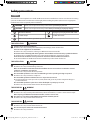
Safety precautions
English
This installation manual explains how to install a Multi Tenant Function Controller that is connects to indoor unit of Samsung
system air conditioner. Please read this manual thoroughly before installing the product. (Please refer to an appropriate
installation manual for any optional product installation.)
WARNING
Hazards or unsafe practices that may result in severe personal injury or death.
CAUTION
Hazards or unsafe practices that may result in minor personal injury or property damage.
Must follow directions. Unplug the power plug from the wall socket.
Do NOT attempt. Do NOT disassemble.
Make sure the machine is grounded to prevent electric shock.
FOR INSTALLATION
WARNING
Contact a service center for installation.
Failure to do so may result in product malfunction, water leakage, electric shock and re.
You must use the supplied wire for installation.
Failure to do so may result in re or damage to a Multi Tenant Function Controller.
All electric work should comply with local regulations and installation work carried out by a qualied technician.
Installation by an unqualied technician may result in product malfunction, electric shock, and re.
Check whether the installation work is performed in accordance with the installation instructions.
Incorrect installation of a Multi Tenant Function Controller may result in electric shock or re.
FOR INSTALLATION
CAUTION
When connecting a wire, do not tighten it too much.
Failure to do so may result in breakage of the wire.
Make sure the Multi Tenant Function Controller installation doesn't cause interference with other electrical
appliances, particularly in a hospital etc.
Failure to do so may result in abnormal operation.
Do not install the product in an area where combustible gas leaks or possible gas leakage is expected.
Failure to do so may result in re or explosion.
Do not install the product in conditions where it is exposed to oil, steam etc.
Use of the product in an area exposed to oil, steam, sulfuric acid gas etc may result in component damage or
product malfunction.
Do not install the product in a place where acid or alkali liquid or special sprays are used.
Failure to do so may result in electric shock or abnormal operation.
FOR OPERATION
WARNING
Do not remodel or repair the Multi Tenant Function Controller yourself.
Failure to do so may result in product malfunction, electric shock and re, so contact a service center for repair.
When disposing of a Multi Tenant Function Controller, contact a service center.
Do not move or reinstall an installed Multi Tenant Function Controller yourself.
Failure to do so may result in electric shock or re.
FOR OPERATION
CAUTION
Make sure that water does not permeate inside the Multi Tenant Function Controller.
Failure to do so may result in electric shock or re.
Do not connect power cable to the control cable terminal.
Failure to do so may result in re.
보조전원 모듈_MCM-C210_IM_EN+FR_03929A-06.indd 2 2016-04-21 오후 3:30:08

3
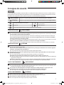
Consignes de sécurité
français
Ce manuel d'installation explique comment installer un contrôleur de fonctions multi-tenant connecté au module intérieur
de votre climatiseur Samsung. Veuillez lire attentivement ce manuel préalablement à l'installation de l'appareil. (Concernant
l'installation de tout appareil en option, veuillez vous reporter au manuel d'installation approprié.)
AVERTISSEMENT
Dangers ou usages dangereux pouvant entraîner des blessures graves ou la mort.
ATTENTION
Dangers ou usages dangereux pouvant entraîner des blessures mineures ou des dégâts matériels.
Suivre impérativement les instructions.
Débrancher la che d'alimentation électrique
de la prise murale.
Ne PAS faire. Ne PAS démonter.
S'assurer que l'appareil est mis à la terre pour éviter tout choc électrique.
POUR L'INSTALLATION
AVERTISSEMENT
Contactez un centre de services pour l'installation.
Le non-respect de cette consigne risque d'endommager l'appareil et de provoquer fuite d'eau, choc électrique et incendie.
Vous devez utiliser le câble fourni pour l'installation.
Le non-respect de cette consigne peut provoquer un incendie ou endommager le contrôleur de fonctions multi-tenant.
Tous les travaux électriques doivent être eectués en accord avec la réglementation locale et les travaux d'installation
doivent être eectués par un électricien qualié.
L'installation par un technicien non qualié risque d'endommager l'appareil et de provoquer un choc électrique et un incendie.
Vériez si les travaux d'installation sont eectués en accord avec les consignes d'installation.
Une installation incorrecte du contrôleur de fonctions multi-tenant peut provoquer un choc électrique ou un incendie.
POUR L'INSTALLATION
ATTENTION
Lors du branchement d'un câble, ne le serrez pas trop fort.
Cela risque d'endommager le câble.
Assurez-vous que le contrôleur de fonctions multi-tenant ne provoque pas d'interférence avec d'autres appareils
électriques, en particulier dans un hôpital, etc.
Le non-respect de cette consigne risque de provoquer un dysfonctionnement.
N'installez pas l'appareil dans un emplacement présentant des fuites de gaz combustible ou s'il existe un risque
potentiel de fuite de gaz.
Le non-respect de cette consigne risque de provoquer un incendie ou une explosion.
N'installez pas l'appareil dans des conditions où il risque d'être exposé à l'huile, à la vapeur, etc.
L'utilisation de l'appareil dans une zone exposée à l'huile, la vapeur, le gaz acide sulfureux, etc. risque d'endommager
l'appareil ou le composant.
N'installez pas l'appareil dans une zone en présence d'acide ou de liquide alcalin ou bien d'une pulvérisation particulière.
Le non-respect de cette consigne risque de provoquer un choc électrique ou un dysfonctionnement.
POUR LE FONCTIONNEMENT
AVERTISSEMENT
Ne modiez pas ni ne réparez pas vous-même le contrôleur de fonctions multi-tenant.
Le non-respect de cette consigne risque de provoquer un dysfonctionnement de l'appareil, un choc électrique et un
incendie. Par conséquent, contactez le service après-vente.
Lors de la mise au rebut du contrôleur de fonctions multi-tenant, veuillez contacter le service après-vente.
Ne déplacez pas ou ne réinstallez pas vous-même un contrôleur de fonctions multi-tenant.
Le non-respect de cette consigne risque de provoquer un choc électrique ou un incendie.
POUR LE FONCTIONNEMENT
ATTENTION
Veillez à éviter tout contact du contrôleur de fonctions multi-tenant avec de l'eau.
Le non-respect de cette consigne risque de provoquer un choc électrique ou un incendie.
Ne branchez pas le câble d'alimentation à la borne de commande.
Le non-respect de cette consigne risque de provoquer un incendie.
보조전원 모듈_MCM-C210_IM_EN+FR_03929A-06.indd 3 2016-04-21 오후 3:30:09

4
Preparing for installation
Checklist before installation
About power supply
Electric transformer and the power cables, for power supply, should be purchased separately and they are not provided by
manufacturer.
About installation cables
Each power cables should be wired from the electrical transformer or indoor units to the installation location of the Multi
Tenant Function Controller and wiring work must be done in advance so that they can be connected to each other.
About protection box
Protection box for the Multi Tenant Function Controller must be purchased separately. Installing the Multi Tenant Function
Controller within an Ingress Protection (IP) box or a box made of metal metrial is recommended.
Accessories
Name
Multi Tenant Function
Controller
DC power cable
(5 V)
Installation manual Holder PBA
Quantity 1 1 1 4
Image
보조전원 모듈_MCM-C210_IM_EN+FR_03929A-06.indd 4 2016-04-21 오후 3:30:09

5
Name of the parts and product dimension
DC 12 V Output
AC 24 V Input
AC 220 V Input
DC 5 V Output
110 mm
75 mm
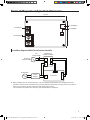
Installation diagram of Multi Tenant Function Controller
L
N
V2
V1
L
N
V2
V1
Indoor Unit
Multi Tenant
Function Controller
DC 5 V
AC 24V 1A
(Not provided)
AC 200-240V
Download
Circuit
Breaker
Fuse
(Not provided)
When installing a the AC 24V transformer, use a box or metal material with the same or higher level of re
retardant as the IP box. You should close the gap around the place where wires are input so that any rodents or
water cannot come into the box, and then remove all the sharp surfaces.
- AC 24V needs to be purchased at a local shop. (You should purchase a rated part.)
보조전원 모듈_MCM-C210_IM_EN+FR_03929A-06.indd 5 2016-04-21 오후 3:30:09

6
Installing the product
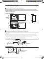
Installing the Multi Tenant Function Controller box
The size of the Multi Tenant Function Controller box should be more than 210 mm(W) x 130 mm(H) x 100 mm(D).
Fix the plate (PD, MD) to the Multi Tenant Function Controller box and assemble the holders (for xing PBA) to install the
Multi Tenant Function Controller.
- Make 4 holes to x PBA on the plate.
HOLE SIZE : 5 mm diameter
W
D
H
65 mm
85 mm
4 PBA holder
holes
100 mm
Plate
75 mm
25 mm or
more
25 mm or
more
110 mm
50 mm
or more
50 mm
or more
MTFC
HOLDER 4EA
Close the gap completely to prevent
rodents or water from entering.
The installation location of Multi Tenant Function Controller box
For ceiling type indoor unit, the distance between an indoor unit and the Multi Tenant Function Controller box should be
within 3 m.
When the Multi Tenant Function Controller is installed, the Multi Tenant Function Controller box should be xed.
For wall-mounted indoor unit, the Multi Tenant Function Controller box should be concealed inside the wall and the
distance between an indoor unit and Multi Tenant Function Controller box should be within 3 m.
For ceiling type: 1 WAY CASSETTE, 4 WAY CASSETTE and DUCT
Within 3 m
Indoor Unit
Multi Tenant Function
Controller box
For wall-mounted type
Within
3 m
Indoor
Unit
Wall
Multi Tenant Function
Controller box
보조전원 모듈_MCM-C210_IM_EN+FR_03929A-06.indd 6 2016-04-21 오후 3:30:10

7
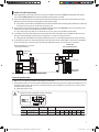
Indoor unit cable connection
After cutting off the power of the indoor unit, connect the cable between the AC POWER terminal block of the indoor
unit and the INDOOR POWER terminal block of the Multi Tenant Function Controller.
Connect the cable between the Commnunication/Power terminal block V1/V2 of the indoor unit and the V1/V2 of the
Multi Tenant Function Controller, complying the correct voltage polarity.
If the cable is connected incorrectly, Multi Tenant Function Controller will not work properly. Furthermore, indoor unit
communication error may occur and entire system may stop.
Connect the DC power cable (5 V), which is included in the box, between the DOWNLOAD conenctor of the indoor unit
and the DC 5 V connector of the Multi Tenant Function Controller.
If you cut the DC power cable (5 V) and extend it on your own, it may cause problem on the product.
To check the connection of the cable, disconnect the AC power cable of the indoor unit and supply the AC 24 V power.
If the green LED of the Multi Tenant Function Controller turns on, cable is correctly connected.
If the green LED of the Multi Tenant Function Controller does not turn on, check if the polarity of the V1 and V2 are correct.
For the products with no V1 and V2 terminal block on the indoor units (such as RAC, 2WAY), connect the #1 wire (RED) of
the 4P connector wire, connected to the communication SUB PCB, to the V1. (V2 connection is not required)
N L
AC power for an indoor unit INDOOR POWER
F1 F2 V1 V2 F3 F4
Use UL Standard, Class 2, AC24V
1A electric transformer
AC 24V
AC 24V ±15 %
50/60 Hz
1A
Indoor unit
Download
Indoor unit
communication/power
DC power cable (5 V)
Connecting power cable
1. Make sure to cut-off the power before connecting the power cable.
2. Use appropriate tools to connect the cables rmly within rated torque range so that it can withstand external forces, and
arrange the cables neatly so that cover or any other parts won't get loose. When the connection is loose, there is risk of
overheat, electric shock or re.
Tightening torque: 6 N•cm
CAUTION
• Speci cation of the compatible compressed terminal
Range of permitted wires Rated size Stud size Basic size (mm)
AWG mm
2
mm
2
mm t øD G E F W L
22~16 0.25~1.65 1.5 3 0.7 3.8 10.0 4.5 6.5 6.0 21.2
보조전원 모듈_MCM-C210_IM_EN+FR_03929A-06.indd 7 2016-04-21 오후 3:30:10

8
Installing the product
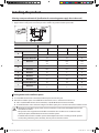
Selecting a compressed terminal (Speci cation for connecting power supply of an indoor unit)
1. Select a solderless ring terminal for a power cable according to the nominal dimensions for cable.
2. Apply insulation coating to the connection part of the solderless ring terminal and the power cable.
Silver solder
Nominal dimensions for cable
1.5 2.5 4
Nominal dimensions for screw
4 4 4 4 4
B
Standard dimension
6.6 8 6.6 8.5 9.5
Allowance
±0.2 ±0.2 ±0.2
D
Standard dimension
3.4 4.2 5.6
Allowance
+0.3
-0.2
+0.3
-0.2
+0.3
-0.2
d1
Standard dimension
1.7 2.3 3.4
Allowance
±0.2 ±0.2 ±0.2
E Minimum
4.1 6 6
F Minimum
6 6 5
L Maximum
16 17.5 20
d2
Standard dimension 4.3 4.3 4.3
Allowance
+0.2
0
+0.2
0
+0.2
0
t
Minimum 0.7 0.8 0.9
Setting indoor unit installation option
To use the Multi Tenant Function Controller, installation option must be changed.
SEG2 of the installation option on installed indoor units must be set to '5' and SEG11 must be set to '2'.
SEG11: 0 (Disable Multi Tenant Function Controller) / 2 (Enable Multi Tenant Function Controller)
For detail information on the method of setting the installation option, please refer to the indoor unit installation manual.
• Wired remote controller for group control cannot be installed to an indoor unit which Multi Tenant Function
controller was installed.
• EEV operation of the stopped Heat mode will be controlled in same condition as noise reduction control
option (0/80 option) when Multi Tenant Function Controller operates.
• If the Multi Tenant Function Controller operates while multiple indoor units are working in mixed operation
mode (cooling and heating at the same time), dew may form on the indoor unit fan.
CAUTION
보조전원 모듈_MCM-C210_IM_EN+FR_03929A-06.indd 8 2016-04-21 오후 3:30:10

9
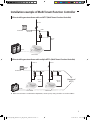
Installation example of Multi Tenant Function Controller
When installing one transformer with one MTFC (Multi Tenant Function Controller)
AC 220V
AC 24V 1A
Transformer
MTFC
DC 12V
DC 5V
Comm.
Indoor Unit#1
When installing one transformer with multiple MTFCs (Multi Tenant Function Controller)
AC 220V AC 220V
AC 24V
N*1A
Transformer
MTFC
MTFC
"N"
(Number of
MTFC)
DC 12V
DC 5V
DC 12V
DC 5V
Comm.
Indoor Unit#2Indoor Unit#1
When one transformer is installed with multiple MTFCs, current capacity setting should be 1A x number of MTFC.
보조전원 모듈_MCM-C210_IM_EN+FR_03929A-06.indd 9 2016-04-21 오후 3:30:11

보조전원 모듈_MCM-C210_IM_EN+FR_03929A-06.indd 10 2016-04-21 오후 3:30:11
-
 1
1
-
 2
2
-
 3
3
-
 4
4
-
 5
5
-
 6
6
-
 7
7
-
 8
8
-
 9
9
-
 10
10