
PROPANE CONSTRUCTION FORCED AIR HEATER
OWNER’S MANUAL
170,000 BTU/HR VARIABLE WITH BUILT-IN THERMOSTAT
IMPORTANT: Read and understand this manual before
assembling, starting or servicing heater. Improper use
of heater can cause serious injury. Keep this manual for
future reference.
GENERAL HAZARD WARNING:
Failure to comply with the precautions and instructions
provided with this heater, can result in death, serious
bodily injury and property loss or damage from hazards
of fire, explosion, burn, asphyxiation, carbon monoxide
poisoning and/or electrical shock.
Only persons who can understand and follow the in-
structions should use or service this heater.
If you need assistance or heater information such as an in-
structions manual, labels, etc. Contact the manufacturer.
Save this manual for future reference.
For more information, visit www.desatech.com
TABLE OF CONTENTS
Safety Information ............................................... 2
Product Identification ........................................... 3
Unpacking ........................................................... 3
Theory of Operation ............................................ 4
Propane Supply ................................................... 4
Installation ........................................................... 4
Ventilation
........................................................... 5
Operation ............................................................. 5
Storage ................................................................ 6
Maintenance ........................................................ 6
Troubleshooting ...................................................
7
Service Procedures ............................................. 8
Specifications .................................................... 10
Wiring Diagram .................................................. 10
Accessories ........................................................11
Technical Servi
ce ...............................................11
Replacement Parts .............................................11
Illustrated Parts Breakdown and Parts List ....... 12
Warranty and Repair Service ............................ 14

www.desatech.com
113959-01B
2
SAFETY INFORMATION
WARNING: This product
contains and/or generates
chemicals known to the State
of California to cause cancer or
birth defects or other reproduc-
tive harm.
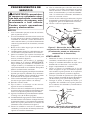
WARNING: Fire, burn, inha-
lation and explosion hazard.
Keep solid combustibles, such
as building materials, paper or
cardboard, a safe distance away
from the heater as recommended
by the instructions. Never use
the heater in spaces which do or
may contain volatile or airborne
combustibles or products such
as gasoline, solvents, paint thin-
ner, dust particles or unknown
chemicals.
WARNING: Not for home or
recreational vehicle use.
The heater is designed for use as a construction
heater in accordance with ANSI Z83.7/CGA2.14.
Other standards govern the use of fuel gases
and heating products for specific uses. Your lo-
cal authority can advise you about these. The
primary purpose of construction heaters is to
provide temporary heating of buildings under
construction, alteration or repair. Properly used,
the heater provides safe economical heating.
Products of combustion are vented into the area
being heated.
We cannot foresee every use which may be made of
our heaters. Check with your local fire safety au
-
thority if you have questions about heater use.
Other standards govern the use of fuel gases and
heat producing products for specific uses. Your
local authorities can advise you about these.
Carbon Monoxide Poisoning: Some people are
more affected by carbon monoxide than others.
Early signs of carbon monoxide poisoning re-
semble the flu, with headaches, dizziness and/or
nausea. If you have these signs, the heater may not
be working properly. Get fresh air at once! Check
for proper ventilation and have heater serviced.
Propane Gas: Propane gas is odorless. An odor-
making agent is added to propane gas. The odor
helps you detect a propane gas leak. However, the
odor added to propane gas can fade. Propane gas
may be present even though no odor exists.
Make certain you read and understand all warn
-
ings. Keep this manual for reference. It is your
guide to safe and proper operation of this heater.
1. This product has been approved for use in the
Commonwealth of Massachusetts.
2. Install and use heater with care. Follow all
local ordinances and codes. In the absence
of local ordinances and codes, refer to the
Standard for Storage and Handling of Lique
-
fied Petroleum Gas, ANSI/NFPA 58 and the
Propane Gas Installation Code, CAN/CGA
B149.2. This instructs on the safe storage and
handling of propane gases.
3. Use only the electrical voltage and frequency
specified on model plate. The electrical con
-
nections and grounding of the heater shall fol-
low the National Electric Code, ANSI/NFPA
70 or the Canadian Electrical Code, Part 1.
4. Electrical grounding instructions — This
appliance is equipped with a three-prong
(grounding) plug for your protection against
shock hazard and should be plugged directly
into a properly grounded three-prong recep
-
tacle or extension cord.
5. Use only the hose and factory preset regulator
provided with the heater.
6. Use only propane gas set up for vapor with
-
drawal.
7. Provide adequate ventilation. Before using
heater, provide at least a three-square-foot
opening of fresh, outside air for each 100,000
Btu/Hr (105,500 k/j) of rating.
8. For indoor use only. Do not use heater out
-
doors.
9. Do not use heater in occupied dwellings or in
living or sleeping quarters.
10. Do not use heater in a basement or below
ground level. Propane gas is heavier than air.
If a leak occurs, propane gas will sink to the
lowest possible level.
11. Keep appliance area clear and free from com
-
bustible materials, gasoline, paint thinner and
other flammable vapors and liquids. Dust is
combustible. Do not use heater in areas with
high dust content.
12. Minimum heater clearances from combustible
materials:
Outlet: 8 Ft. (2.4 m), Sides: 2 Ft. (.6 m), Top:
6 Ft. (1.8 m), Rear: 2 Ft. (.6 m)

www.desatech.com
113959-01B
3
13. Keep heater at least six feet from propane
tank(s). Do not point heater at propane tank(s)
within 20 feet (6.1 m).
14. Keep propane tank(s) below 100° F (38° C).
15. Check heater for damage before each use. Do
not use a damaged heater.
16. Check hose before each use of heater. If highly
worn or cut, replace with hose specified by
manufacturer before using heater.
17. Locate heater on stable and level surface if
heater is hot or operating.
18. Never block air inlet (rear) or air outlet (front)
of heater.
19. Keep heater away from strong drafts, wind,
water spray, rain or dripping water.
20. Keep children and animals away from
heater.
21. This heater is equipped with a thermostat.
Heater may start at anytime.
22. Never move, handle or service a hot or operat
-
ing heater. Severe burns may result. You must
wait 15 minutes after turning heater off.
23. To prevent injury, wear gloves when handling
heater.
24. Never attach duct work to heater.
25. Do not alter heater. Keep heater in its original
state.
26. Do not use heater if altered.
27. Turn off propane supply to heater and unplug
heater when not in use.
28. Use only original replacement parts. This
heater must use design-specific parts. Do
not substitute or use generic parts. Improper
replacement parts could cause serious or fatal
injuries.
SAFETY INFORMATION
Continued
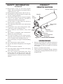
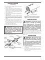
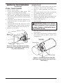
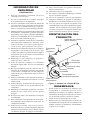
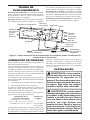
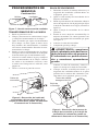
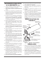
Hot Air Outlet (Front)
Variable
Heat Control
Power
Cord
Hose/Regulator
Assembly
Inlet
Connector
Thermostat
Knob
PRODUCT
IDENTIFICATION
Figure 1 - 170,000 Btu/Hr Model
Handle
Fan
Guard
UNPACKING
1. Remove all packing items applied to heater for
shipment. Keep plastic cover caps (attached to
inlet connector and hose/regulator assembly)
for storage.
2. Remove all items from carton.
3. Check all items for shipping damage. If heater
is damaged, promptly inform dealer where you
bought heater.

www.desatech.com
113959-01B
4
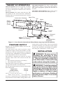
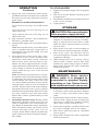
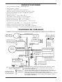
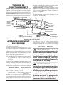
THEORY OF OPERATION
The Fuel System: The hose/regulator assembly
attaches to the propane gas supply. The propane
gas moves through the solenoid valve and out
the nozzle.
The Air System: The motor turns the fan. The
fan pushes air into and around the combustion
chamber. This air is heated and provides a stream
of clean, hot air.
Air For Combustion
And Heating
Fuel
Combustion Chamber
Spark Plug
Figure 2 - Cross Section Operational View (Heater may vary from illustration)
Clean
Heated
Air Out
(Front)
Cool
Air In
(Back)
Fan
Motor
Power
Cord
Hose/Regulator
Assembly
Solenoid
Valve
Nozzle
The Ignition System: The direct spark ignitor
(DSI) sends voltage to the spark plug/ignitor.
The spark plug/ignitor ignites the fuel and air
mixture.
The Safety Control System: This system causes
the heater to shut down if the flame goes out.
PROPANE SUPPLY
Propane gas and propane tank(s) are to be fur-
nished by the user.
Use this heater only with a propane vapor
withdrawal supply system. See Chapter 5 of the
Standard for Storage and Handling of Liquefied
Petroleum Gas, ANSI/NFPA 58. Your local library
or fire department will have this booklet.
The amount of propane gas ready for use from
propane tanks varies. Two factors decide this
amount:
1. The amount of propane gas in tank(s)
2. The temperature of tank(s)
The chart below shows the number of 100 pound
(45 kg) tanks needed to run this heater.
Do not operate this product with any tank smaller
than 100 pounds.
Temperature Number
at tank location of tanks
above 20° F (-7° C) 2
20° F (-7° C) to -10° F (-23° C) 3
below -10° F (-23° C) (Use larger tank)
Less gas is vaporized at lower temperatures. You
may need two or more 100 lb. (45 kg) tanks or one
larger tank in colder weather. Your local propane
gas dealer will help you select the proper supply
system. The minimum surrounding-air tempera
-
ture rating for each heater is -20°F (-29°C).
INSTALLATION
WARNING: Review and un-
derstand the warnings in the
Safety Information section, page
2. They are needed to safely op-
erate this heater. Follow all local
codes when using this heater.
WARNING: Test all gas piping
and connections for leaks after
installing or servicing. Never use
an open flame to check for a leak.
Apply a mixture of liquid soap
and water to all joints. Bubbles
forming show a leak. Correct all
leaks at once.

www.desatech.com
113959-01B
5
1. Provide propane supply system (see Propane
Supply, page 4).
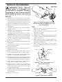
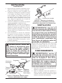
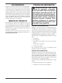
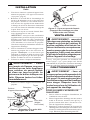
2. Connect POL fitting on hose/regulator as
-
sembly to propane tank(s). Turn POL fitting
counterclockwise into threads on tank. Tighten
firmly using wrench. Tighten regulator with
vent pointing down.
3. Connect hose to inlet connector. Tighten firmly
using a wrench.
IMPORTANT: Extra hose or piping may be
used if needed. Install extra hose or piping
between hose/regulator assembly and propane
tank. You must use the regulator supplied with
heater.
4. Open propane supply valve on propane tank(s)
slowly.
Note: If not opened slowly, excess-
flow check valve on propane tank may stop
gas flow. If this happens, close propane supply
valve and open again slowly.
5. Check all connections for leaks.
WARNING: Never use an
open flame to check for a leak.
Apply a mixture of liquid soap
and water to all joints. Bubbles
forming show a leak. Correct all
leaks at once.
6. Close propane supply valve.
INSTALLATION
Continued
Figure 4 - Hose and Inlet Connector
(Heater may vary from illustration)
Hose
Inlet Connector
Figure 3 - Regulator With Vent Pointing
Down
Propane
Tank
Hose
Regulator
Vent
(pointing
down)
POL
Fitting
Supply
Valve
VENTILATION
WARNING: Follow the mini-
mum fresh, outside air ventila
-
tion requirements. If proper
fresh, outside air ventilation is
not provided, carbon monoxide
poisoning can occur. Provide
proper fresh, outside air ventila-
tion before running heater.
Provide a fresh air opening of at least 3 ft
2
(0.28 m
2
) for each 100,000 Btu/Hr (105,500 k/j)
rating. Provide extra fresh air if more heaters are
being used.
OPERATION
WARNING: Review and un-
derstand the warnings in the
Safety Information section, page
2. They are needed to safely op-
erate this heater. Follow all local
codes when using this heater.
TO START HEATER
1. Follow all installation, ventilation and safety
information.
2. Locate heater on stable and level surface.
Make sure strong drafts do not blow into front
or rear of heater.

www.desatech.com
113959-01B
6
3. Plug power cord of heater into a three-prong,
grounded extension cord. Extension cord must
be at least six feet long. Extension cord must
be UL listed.
Extension Cord Size Requirement
Up to 50 feet (15 m) long, use 18 AWG rated
cord.
51 to 100 feet (15.5 to 30.5 m) long, use 16
AWG rated cord.
101 to 200 feet (30.78 to 61 m) long, use 14
AWG rated cord.
4. Plug extension cord into a 120 volt/60 hertz,
three-hole, grounded outlet.
5. Open propane supply valve on propane tank(s)
slowly.
Note: If not opened slowly, excess-flow check
valve on propane tank may stop gas flow. If
this happens, close propane supply valve and
open again slowly.
6. Turn thermostat control knob fully coun
-
terclockwise to the “cooler” position. Turn
thermostat control knob slowly clockwise
until electric motor and fan begin to run.
Heater will start in approximately 3 seconds.
Adjust thermostat control knob to warmer or
cooler setting as needed. To control the heat
output, adjust the gas valve to the desired
temperature.
Note: If heater does not start after 3 seconds,
the ignition control will automatically attempt
to start heater one time. If heater fails to start
on this attempt, the safety control will "lock
out" and no further automatic restarts will be
attempted. This could occur if air remains in
fuel line. If heater fails to start on this attempt,
turn thermostat knob to the “cooler” position
until the motor stops turning. Wait ten seconds
for safety control to reset, then turn control
knob to the “warmer” position and try to start
heater again.
7. Thermostat Operation Only: During normal
thermostat operation, heater will cycle off
when air temperature rises to thermostat set-
ting. When air temperature drops sufficiently
below thermostat setting, the electric motor
and fan will begin to run. After 15 to 60
seconds, heater burner should automatically
ignite and provide heat to maintain tempera-
ture setting.
OPERATION
Continued
TO STOP HEATER
1. Tightly close propane supply valve on propane
tank(s).
2. Wait a few seconds. Heater will burn gas left
in supply hoses.
3. Turn thermostat knob fully counterclockwise
to the “cooler” position.
4. Unplug heater.
STORAGE
CAUTION: Disconnect heater
from propane supply tank(s).
1. Store propane tank(s) in safe manner. See
Chapter 5 of Standard for Storage and Han
-
dling of Liquefied Petroleum Gases, ANSI/
NFPA 58 and/or CAN/CGA B149.2. Follow
all local codes.
2. Place plastic cover caps over brass fittings on
inlet connector and hose/regulator assembly.
3. Store in dry, clean and safe place. Do not
store hose/regulator assembly inside heater
combustion chamber.
4. When taking heater out of storage, always
check inside of heater. Insects and small
animals may place foreign objects in heater.
Keep inside of heater free from combustible
and foreign objects.
MAINTENANCE
WARNING: Never service
heater while it is plugged in,
connected to propane supply,
operating or hot. Severe burns
and electrical shock can occur.
1. Keep heater clean. Clean heater annually or
as needed to remove dust and debris. If heater
is dirty or dusty, clean heater with a damp
cloth.
2. Inspect heater before each use. Check connec
-
tions for leaks. Apply mixture of liquid soap
and water to connections. Bubbles forming
show a leak. Correct all leaks at once.
3. Inspect hose/regulator assembly before each
use. If hose is highly worn or cut, replace.
4. Have heater inspected yearly by a qualified
service agency.
5. Keep inside of heater free from combustible
and foreign objects.

www.desatech.com
113959-01B
7
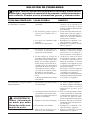
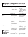
POSSIBLE CAUSE
1. No electrical power to heater
2. Fan hitting inside of heater
shell
3. Fan blades bent
4. Defective motor
1. User did not follow installa
-
tion or operation instructions
properly
2. No spark at spark plug. To test
for spark, follow step 8 under
Spark Plug, page 8. If you see
spark at spark plug, have heater
serviced by qualified service
person. If no spark seen:
A) Loose or disconnected
spark plug wire
B) Bad spark plug
C) Bad spark transformer
1. Propane supply may be inad
-
equate
2. High surrounding air tem
-
perature causing thermal limit
device to shut down heater.
3. Restricted air flow
4. Damaged fan
5. Excessive dust or debris in
surrounding area
REMEDY
1. Check voltage to electrical
outlet. If voltage is good,
check heater power cord for
breaks
2. Adjust motor/fan mount to
keep fan from hitting inside of
heater shell. Bend fan mount
if necessary
3. Replace fan. See
Fan, page 8
4. Replace motor. See Motor,
page 8
1. Repeat installation and opera
-
tion instructions. See Instal
-
lation, page 4 and Operation,
page 5
2. A) Check spark plug wire.
Tighten or reattach loose spark
plug wire. See Figure 8, page
9 for spark plug wire location
B) Replace spark plug. See
Spark Plug
, page 9
C) Replace spark transformer.
See Spark Transformer, page 9
1. A) Refill tank
B) Provide additional and/or
larger tanks. See Propane
Supply, page 4
2. This can happen when running
heater in temperatures above
85° F (29° C). Run heater in
cooler temperatures
3. Check heater inlet and outlet.
Remove any obstructions
4. Replace fan. See
Fan, page 8
5. Clean heater. See Mainte
-
nance, page 6
OBSERVED PROBLEM
Fan does not turn when heater
is plugged in
Heater will not ignite
Heater shuts down while run-
ning
TROUBLESHOOTING
WARNING: Never service heater while it is plugged in, connected
to propane supply, operating or hot. Severe burns and electrical
shock can occur.
WARNING: Use only in areas
free of high dust content.

www.desatech.com
113959-01B
8
SERVICE PROCEDURES
WARNING: Never service
heater while it is plugged in,
connected to propane supply,
operating or hot. Severe burns
and electrical shock can occur.
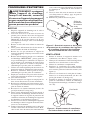
MOTOR
1. With heater on its side, remove access panel.
2. Access ground screw through underside of
heater base. Remove ground screw. Disconnect
the green motor wire and the green power cord
wire from underside of shell (see Figure 5).
3. Remove two black wires from motor to ter
-
minal board.
4. Carefully push motor wires through hole in
bottom of shell.
5. Remove screws holding motor mount to shell.
Use nut-driver (see Figure 5).
6. Carefully pull motor and fan out of shell.
IMPORTANT: Be careful not to damage fan.
Do not set motor and fan down with the weight
resting on fan. This could damage fan pitch.
7. Use hex wrench to loosen setscrew which
holds fan to motor shaft.
8. Remove fan. Be careful not to damage the fan
blade pitch.
9. Use nut driver to remove two nuts that attach
motor to motor mount.
10. Discard old motor.
11. Attach motor to motor mount with two nuts.
Tighten nuts firmly.
12. Replace fan on motor shaft. Make sure set
screw contacts flat surface on motor shaft.
13. Tighten set screw firmly (40-50 inch-pounds
[46.08-57.60 kilogram-centimeters]).
14. Carefully route motor wires through hole in
shell. Place motor, motor mount and fan guard
into rear of heater shell, as shown in Figure 5.
15. Insert screws through heater shell and into
motor mount. Tighten screws firmly.
16. Turn heater on its side to access opening in
bottom of base. Connect green wires from
motor, transformer and power cord to heater
shell using ground nut.
17. Attach two black wires from motor to terminal
board (see Wiring Diagram, page 10, for cor
-
rect locations).
18. Replace access panel.
Figure 5 - Removing Motor and Fan
Guard from Heater (Heater may vary
from illustration)
Screw
Screw
Motor and
Fan Guard
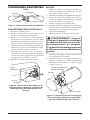
FAN
1 Remove motor, motor mount and fan (see
Motor, steps 1 through 8).
2. Clean fan using soft cloth moistened with
kerosene or solvent.
3. Dry fan thoroughly.
4. Replace fan on motor shaft. Make sure set
-
screw is touching back of flat surface on motor
shaft (see Figure 6).
5. Place setscrew on flat of shaft. Tighten set
-
screw firmly (40-50 inch-pounds [46.08-57.60
kilogram-centimeters]).
6. Place motor, motor mount and fan guard
into rear of heater shell (see
Motor, steps 14
through 18).
Motor Shaft
Fan
Setscrew
Figure 6 - Fan, Motor Shaft and
Setscrew Location
Figure 7 - Fan Cross Section
Fan
Hub
Setscrew
Motor
Shaft

www.desatech.com
113959-01B
9
SERVICE PROCEDURES
Continued
SPARK TRANSFORMER
1. Remove access panel.
2. Locate and disconnect white, black and
orange wires from spark transformer.
3. Remove screw holding spark transformer to
base. Remove sheet metal nut on transformer
and install on new transformer. Discard spark
transformer.
4. Install new spark transformer. Position new
spark transformer in same manner as old
transformer.
5. Connect white, black and orange wires to new
spark transformer. Connect wires to correct ter
-
minals as noted in Wiring Diagram, page 10.
6. Replace access panel.
Figure 9 - Removing Spark Plug Nut
and Spark Plug (Heater may vary from
illustration)
Rear Head
Spark Plug
3/4" Hex
Head Nut
SPARK PLUG
1. Remove motor, motor mount and fan guard
(see Motor, page 8, steps 1 through 6).
2.
Remove orange
spark plug
wire from spark
plug.
3. From front of heater loosen 3/4" hex nut hold-
ing spark plug in place (see Figure 9).
4. Remove spark plug from rear head.
5. Install new spark plug. Attach spark plug to rear
head with ignitor hex nut removed in step 3.
6. Attach spark plug wire.
7. Test for spark.
WARNING: Make sure heater
is disconnected from propane
supply. Heater could ignite caus-
ing severe burns.
Plug into extension cord and watch for spark
at spark plug.
8. Place motor, motor mount and fan guard into
rear of heater shell (see
Motor, page 8, steps
14 through 18).
Figure 8 - Removing Spark Plug Wire
from Spark Transformer (Heater may
vary from illustration)
Bushing
Spark Plug
Wire

www.desatech.com
113959-01B
10
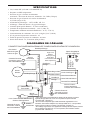
SPECIFICATIONS
• 125,000 - 170,000 Btu/Hr (36.6 - 49.8 kW)
• Propane/LP Fuel
• Gas Supply Pressure to Regulator
Max - Bottle Pressure, Min - 5 psig (34.5 kPa)
• Gas Supply Pressure Regulator out
28" WC (6.97 kPa)
• Electrical Input - 115V, 60 Hz, 1Ø, 3a
• Direct Spark Ignition, interrupted type
• Primary Flame Control - Solid State
• High Temperature Control - 240°F (116°C)
• Minimum Ambient Temp. Rating - 0°F (-17.8°C)
• Fuel Consumption - 5.8 - 7.9 lbs/hr (2.6 - 3.6 kg/hr)
• Fuel Orifice Port No. - 18
• Fuel Orifice Port Size - 0.80 mm
• Heated Air Output - 450 CFM (12.74 cu m/m)
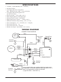
WIRING DIAGRAM
Orange**
CONNECTION DIAGRAM
Green
Spark Plug
If any original wiring as supplied with the heater must
be replaced, it must be replaced with type AWG 105°
C
wire or its equivalent except as indicate
d
(*Type SF2-200. **SGI-250° C)
High Limit
Switch
Gas
Valve
Green
Green
Motor
Flame Control
Line
Neut
Va
lve
Ground
White
White
White
White
Red
Red
Red
Red
Red
Black
Black
Thermostat
Chassis
Ground
Chassis
Ground
Chassis
Ground
Line Cord

www.desatech.com
113959-01B 11
ACCESSORIES
Purchase accessories and parts from your nearest
dealer or service center. If your dealer or service
center can not supply an accessory or part, either
contact your nearest Parts Central (listed in the
separate Authorized Service Center booklet) or
call DESA Heating Products at 1-866-672-6040
for referral information. You can also write to the
address listed on the back page of this manual.
TECHNICAL SERVICE
You may have further questions about this heater.
If so, contact DESA Heating Productsʼ Technical
Service Department at 1-866-672-6040. When
calling, please have your model and serial numbers
of your heater ready.
You can also visit DESA Heating Products' Techni
-
cal Service web site at www.desatech.com.
REPLACEMENT PARTS
WARNING: Use only original
replacement parts. This heater
must use design-specific parts.
Do not substitute or use generic
parts. Improper replacement
parts could cause serious or fa-
tal injuries. This will also protect
your warranty coverage for parts
replaced under warranty.
PARTS UNDER WARRANTY
Contact authorized dealers of this product. If they
canʼt supply original replacement part(s), either
contact your nearest Parts Central or call DESA
Heating Productsʼ Technical Service Department
at 1-866-672-6040.
When calling DESA Heating Products, have
ready:
• your name
• your address
• model and serial numbers of your heater
• how heater was malfunctioning
• purchase date
In most cases, we will ask you to return the part
to the factory.
PARTS NOT UNDER WARRANTY
Contact authorized dealers of this product. If
they canʼt supply original replacement part(s),
either contact your nearest Parts Central or call
DESA Heating Products for referral information
at 1-866-672-6040.
When calling DESA Heating Products, have
ready:
• model number of your heater
• the replacement part number

www.desatech.com
113959-01B
12
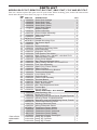
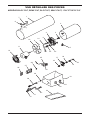
ILLUSTRATED PARTS BREAKDOWN
MODELS BLP170VT, REM170VT, RLP170VT, SBLP170VT, 170-F AND SPC170-F
7
8
1
2
3
4
23
6
21
5
9
11
12
22
33
30
28
15
14
13
34
29
27
32
31
24
25
26
16
18
17
20
19
10

www.desatech.com
113959-01B
13
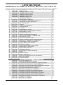
PARTS LIST
MODELS BLP170VT, REM170VT, RLP170VT, SBLP170VT, 170-F AND SPC170-F
This list contains replaceable parts used in your heater. When ordering parts, follow the instructions
listed under Replacement Parts on page 11 of this manual.
KEY
NO. PART NO. DESCRIPTION QTY.
1 113938-01 Outer Shell Orange 1
113938-02 Outer Shell, Red 1
113938-03 Outer Shell, Yellow 1
113938-04 Outer Shell, Green 1
113938-05
Outer Shell, Black 1
2 ** Middle Cylinder 1
3 113940-01 Orifice Assembly 1
4 113937-01 Flame Holder Assembly 1
5 115324-01 High Limit Switch 1
6 113888-01 Orifice Nut 1
7 097917-01 Handle 1
8 097918-01 Handle Mounting Clips 2
9 113948-01 Set Screw, Nyloc 1
10 113950-01 Fan 1
11 113941-01 Motor Assembly
1
12 113942-01 Inlet/Motor Mounting Grille 1
13 113776-01 Hose Assembly 1
14 113862-01 Regulator, 28" WC 1
15 113791-01 POL Excess Flow Valve 1
16 113952-01 Male Fitting Conn. 3/8 MPT x 3/8 SAE FLR 1
17 113951-01 Solenoid Valve, Goyen 1
18 113964-01 Fitting Close Nipple 1
19 113966-01 Burn Rate Adjustment Valve 1
20 113965-01 Elbow Fitting, 3/8 MPT x 1/2 SAE FLR 1
21 113943-01 Fuel Tube Assembly 1
22 113963-01 Spark Plug, Flame Sensor 1
23 113886-01 Spark Plug Nut 1
24 113947-01 Thermostat Mounting Bracket 1
25 113944-01 Thermostat Assembly 1
26 113949-01 Loop Clamp, 5/16 1
27 110287-01 Flame Control 1
28 113864-01 Power Cord Assembly 1
29 113960-01 Terminal Board 1
30 113865-01 Bushing Strain Relief 1
31 113961-01 Knob, Thermostat 1
32 113962-01 Burn Rate Adjustment Knob 1
33 113945-01 Control Box 1
34 113946-01 Access Panel 1
PARTS AVAILABLE - NOT SHOWN
113883-01 Snap Bushing, 5/8 2
113802-07
Model Data Decal 1
113933-04 Operating Instructions Decal, English/Spanish 1
113984-03 Warning Decal, English/Spanish
1
113984-04 Operating Instructions/Warning Decal, French 1
099504-08 Thermostat Warning Decal 1
113907-01 Warning Electrical Decal 1
113953-01
Wiring Schematic Decal 1
097650-01 Tradename Decal, Master 1
113858-04 Tradename Decal, All-Pro 1
113858-05 Tradename Decal, Universal 1
109111-03 Tradename Decal, Reddy
1
110789-01 Tradename Decal, Remington 1
113914-01 Hang Tag, English 1
113914-02 Hang Tag, Spanish 1
113914-03 Hang Tag, French
1
**Not a field
replaceable
part.

2701 Industrial Drive
P.O. Box 90004
Bowling Green, KY 42102-9004
ATTN: Customer Service Department
WARRANTY AND REPAIR SERVICE
KEEP THIS WARRANTY
LIMITED WARRANTIES FOR NEW AND FACTORY
RECONDITIONED PRODUCTS
New Products: DESA Heating Products warrants this heater and any parts thereof, to be free of defects in materials
and workmanship for one (1) year from the date of first purchase, when operated and maintained in accordance
with the manufacturer's instructions. These warranties are extended only to the original retail purchaser, when
proof of purchase is provided.
Factory Reconditioned Heaters: DESA Heating Products warrants this factory reconditioned heater and any parts
thereof, to be free of defects in materials and workmanship for thirty (30) days from the date of first purchase,
when operated and maintained in accordance with the manufacturer's instructions. These warranties are extended
only to the original retail purchaser, when proof of purchase is provided.
These warranties cover only the cost of parts and labor required to restore the product to proper operating condition.
Transportation and incidental costs associated with warranty repairs are not reimbursable under this warranty.
Warranty service is available only through authorized dealers and service centers.
This warranty does not cover defects resulting from misuse, abuse, negligence, accidents, lack of proper mainte
-
nance, normal wear, alteration, modification, tampering, contaminated fuels, repair using improper parts or repair by
anyone other than an authorized dealer or service center. Routine maintenance is the responsibility of the owner.
THIS EXPRESS WARRANTY IS GIVEN IN LIEU OF ANY OTHER WARRANTY EITHER EXPRESSED
OR IMPLIED, INCLUDING WARRANTIES OF MERCHANTABILITY AND FITNESS FOR A PARTICULAR
PURPOSE.
DESA Heating Products assumes no responsibility for indirect, incidental or consequential damages. Some states
do not allow the exclusion or limitation of incidental or consequential damages or limitations or exclusions may
not apply to you. This limited warranty gives you specific legal rights and you may also have other rights which
vary from state to state.
We reserve the right to amend these specifications at any time without notice. The only warranty applicable is our
standard written warranty. We make no other warranty, expressed or implied.
WARRANTY SERVICE
Should your heater require service, return it to your nearest authorized service center. Proof of purchase must be
presented with the heater. The heater will be inspected. A defect may be caused by faulty materials or workman
-
ship. If so, DESA Heating Products will repair or replace the heater without charge.
REPAIR SERVICE
Return your heater to your nearest authorized service center. Repairs not covered by the warranty will be billed at
standard prices. Each Service Center is independently owned and operated. We reserve the right to amend these
specifications at any time without notice. When writing, always include model number and serial number. For
information, write:
Model
Serial No.
Date of Purchase

CALENTADOR DE AIRE FORZADO DE PROPANO PARA
CONSTRUCCIÓN
MANUAL DEL PROPIETARIO
VARIABLE DE 170,000 BTU/H CON TERMOSTATO INTEGRADO
Guarde este manual para referencias futuras.
Para obtener más información, visite www.desatech.com
IMPORTANTE: lea y comprenda este manual antes de
ensamblar, encender o dar servicio al calentador. El uso
inadecuado del calentador puede causar lesiones gra-
ves. Conserve este manual para referencias futuras.
ADVERTENCIA GENERAL DE PELIGRO:
El incumplimiento de las precauciones e instrucciones pro-
porcionadas con este calentador puede causar la muerte,
lesiones físicas graves y pérdidas o daños a la propiedad oca-
sionados por incendios, explosiones, quemaduras, asfixia,
intoxicación con monóxido de carbono y/o electrocución.
Únicamente las personas que puedan entender y seguir las
instrucciones deberán usar o dar servicio a este calentador.
Si necesita ayuda o información sobre el calentador, como
por ejemplo un manual de instrucciones, etiquetas, etc., co-
muníquese con el fabricante.
TABLA DE CONTENIDO
Información de seguridad .................................... 2
Identificación del producto ...................................
3
Desempaque ....................................................... 3
Teoría de funcionamiento ....................................
4
Suministro de propano ........................................ 4
Instalación ........................................................... 4
Ventilación ...........................................................
5
Funcionamiento ................................................... 5
Almacenamiento .................................................. 6
Mantenimiento ..................................................... 6
Solución de problemas ....................................... 7
Procedimientos de servicio ................................. 8
Especificaciones ................................................ 10
Diagrama de cableado ...................................... 10
Accesorios ..........................................................11
Servicio técnico ..................................................11
Piezas de repuesto .............................................11
Clasificación ilustrada de piezas y lista de piezas ....12
Garantía y servicio de reparación ..................... 14

www.desatech.com
113959-01B
2
INFORMACIÓN DE
SEGURIDAD
ADVERTENCIA: este produc-
to contiene y/o genera químicos
reconocidos por el Estado de Ca
-
lifornia como causantes de cán
-
cer o de defectos de nacimiento,
u otros daños reproductivos.
ADVERTENCIA: peligro de
incendio, quemaduras, inhalación
y explosiónMantenga los combus-
tibles sólidos, como materiales de
construcción, papel o cartón a una
distancia segura del calentador
según se recomienda en las ins-
trucciones. Nunca use el calenta-
dor en áreas que contengan o que
puedan contener combustibles
volátiles o que se acumulan en
el aire o bien productos como
gasolina, solventes, diluyente
de pintura, partículas de polvo o
químicos desconocidos.
ADVERTENCIA: no usar
en residencias ni en vehículos
recreativos.
El calentador está diseñado para usarse como
calentador para construcción conforme a la norma
ANSI Z83.7/CGA2.14. Otras normas rigen el uso
de gases combustibles y productos de calefacción
para usos específicos. La autoridad local puede
informarle acerca de éstas. El propósito principal de
los calentadores para construcción es proporcionar
calentamiento temporal de edificios en construc-
ción, modificación o reparación. Cuando se usa co
-
rrectamente, el calentador proporciona calefacción
económica y segura. Los productos de combustión
se ventilan al área que se está calentando.
No podemos prever todos los usos que se les pueden
dar a nuestros calentadores. Consulte a la autori
-
dad local de seguridad contra incendios si tiene
preguntas acerca del uso de calentadores.
Otras normas rigen el uso de gases combustibles
y productos que producen calor para usos especí
-
ficos. Las autoridades locales pueden informarle
acerca de éstas.
Intoxicación con monóxido de carbono: algunas
personas sufren mayores efectos del monóxido de
carbono que otras. Los primeros signos de intoxi-
cación con monóxido de carbono son semejantes
a los de la gripe, con dolor de cabeza, mareo o
náusea. Si usted presenta estos síntomas, es posible
que el calentador no esté funcionando correcta
-
mente. ¡Respire aire fresco inmediatamente!
Compruebe que haya ventilación adecuada y haga
que reparen el calentador.
Gas propano: el gas propano es inodoro. Al gas
propano se le agrega un agente con olor. El olor
le ayuda a detectar las fugas de gas propano. Sin
embargo, el olor que se añade al gas propano puede
desvanecerse. Es posible que haya gas propano
presente aunque no haya ningún olor.
Asegúrese de leer y comprender todas las adver
-
tencias. Conserve este manual como referencia.
Es su guía para la operación segura y correcta de
este calentador.
1. Este producto ha sido aprobado para su uso
en el Estado de Massachusetts.
2. Instale y use el calentador cuidadosamente.
Siga las ordenanzas y los códigos locales. A
falta de decretos y códigos locales, consulte
la Norma de almacenamiento y manejo de
gas licuado de petróleo, ANSI/NFPA 58 y el
Código de instalación de gas propano, CAN/
CGA B149.2. Ésta proporciona instrucciones
acerca del almacenamiento y manejo seguro
del propano.
3. Use solamente la tensión eléctrica y la frecuen
-
cia especificados en la placa del modelo. Las
conexiones eléctricas y de tierra del calentador
deberán estar de acuerdo al Código eléctrico
nacional, ANSI/NFPA 70 o al Código eléctrico
canadiense, parte 1.
4. Instrucciones para la conexión eléctrica a tierra:
este aparato está equipado con un enchufe de
tres clavijas (con conexión a tierra) para prote
-
gerlo contra el riesgo de descargas eléctricas y
se tiene que conectar directamente a un enchufe
de pared o un cable de extensión de tres ranuras
conectado a tierra correctamente.
5. Use sólo la manguera y el regulador preins
-
talado en la fábrica que se incluyen con el
calentador.
6. Use solamente el montaje de gas propano para
la extracción de vapores.
7. Proporcione una ventilación adecuada. Antes
de usar el calentador, debe existir una abertura
de cuando menos 0.28 m cuadrados (3 pies
cuadrados) para aire fresco del exterior por cada
105,500 k/j (100,000 BTU/h) de clasificación.

www.desatech.com
113959-01B
3
8. Para uso en interiores solamente. No use el
calentador en exteriores.
9. No use el calentador en viviendas ocupadas
ni en dormitorios o alojamientos.
10. No use el calentador en un sótano ni debajo del
nivel del suelo. El gas propano es más pesado
que el aire. Si se produce una fuga, el gas pro
-
pano se asentará en el nivel más bajo posible.
11.
Mantenga el área cerca del aparato despejada y libre
de materiales combustibles, gasolina, diluyentes
para pintura, otros vapores y líquidos inflamables.
El polvo es combustible. No use el calentador en
áreas con un alto contenido de polvo.
12. Distancias mínimas alrededor del calentador
para materiales combustibles: Enchufe: 2.4 m
(8 pies), laterales: 6 m (2 pies), parte superior:
1.8 m (6 pies), parte posterior: 6 m (2 pies)
13. Mantenga el calentador alejado de los tanques
de propano a una distancia de al menos 1.8 m
(6 pies). No apunte el calentador hacia tanques
de propano que se encuentren a una distancia
menor de 6 m (20 pies).
14. Mantenga el (los) tanque(s) de propano a
menos de 38° C (100° F).
15. Antes de cada uso, verifique si el calentador
ha sufrido algún daño. No use un calentador
dañado.
16. Revise la manguera antes de cada uso del ca
-
lentador. Si la manguera está muy desgastada
o con roturas, reemplácela con una manguera
especificada por el fabricante antes de usar el
calentador.
17. Sitúe el calentador en una superficie estable y
nivelada si el calentador está caliente o si está
funcionando.
18. Nunca bloquee la entrada de aire (parte pos
-
terior) ni la salida de aire (parte anterior) del
calentador.
19. Mantenga el calentador alejado de corrientes
fuertes de aire, viento, rocío, lluvia o goteos
de agua.
20. Evite que los niños y los animales se acerquen
al calentador.
21. Este calentador está equipado con termostato.
El calentador puede empezar a funcionar en
cualquier momento.
22. Nunca mueva, maneje o dé servicio a un ca
-
lentador caliente o en funcionamiento. Pueden
producirse quemaduras graves. Debe esperar
15 minutos después de apagar el calentador.
INFORMACIÓN DE
SEGURIDAD
Continuación
Salida de aire caliente
(parte anterior)
Control de calor
variable
Cable de
alimentación
Ensamblaje de
manguera-regulador
Conector
de entrada
Perilla del
termostato
IDENTIFICACIÓN DEL
PRODUCTO
Figura 1 - Modelo de 170,000 BTU/h
Manija
Resguardo
del
ventilador
DESEMPAQUE
1. Retire todos los elementos de empaque que
acompañan al calentador para su envío.
Mantenga los tapones de plástico (fijados al
ensamblaje de manguera-regulador y al conec-
tor de entrada) puestos cuando se guarde.
2. Saque todos los elementos de la caja.
3. Revise todos los elementos para ver si hay da
-
ños debidos al transporte. Si el calentador está
dañado, informe de inmediato al distribuidor
a quien se lo compró.
23. Para evitar lesiones, use guantes cuando ma
-
nipule el calentador.
24. Nunca fije tubería al calentador.
25. No altere el calentador. Mantenga el calenta
-
dor en su estado original.
26. No use el calentador si éste ha sido alterado.
27.
Apague el suministro de propano al calentador y
desenchufe el calentador cuando no esté en uso.
28. Use sólo piezas de repuesto originales. Este
calentador debe usar piezas diseñadas específi
-
camente. No las sustituya ni use piezas genéri
-
cas. El uso de piezas de repuesto inadecuadas
puede ocasionar lesiones graves o fatales.

www.desatech.com
113959-01B
4
TEORÍA DE
FUNCIONAMIENTO
El sistema de combustible: el ensamblaje de man-
guera-regulador se fija al suministro del gas propano.
El gas propano se mueve a través de la válvula de
solenoide y sale por la boquilla.
El sistema de aire: el motor hace girar el ventilador.
El ventilador proporciona aire al interior y alrededor
Air For Combustion
And Heating
Fuel
Cámara de combustión
Bujía de
encendido
Figura 2 - Vista transversal de funcionamiento (el calentador puede ser diferente al
mostrado en la ilustración)
Salida de
aire caliente
y limpio
(parte
anterior)
Entrada
de aire
frío (parte
posterior)
Ventilador
Motor
Cable de
alimentación
Ensamblaje
de manguera-
regulador
Válvula de
solenoide
Boquilla
de la cámara de combustión. Este aire se calienta y
proporciona una corriente de aire limpio y caliente.
El sistema de encendido: el encendido de chispa
directa (DSI, por sus siglas en inglés) envía tensión
eléctrica a la bujía/encendedor. La bujía/encendedor
hace que el combustible y la mezcla de aire ardan.
El sistema de control de seguridad: este sistema hace
que el calentador se apague si la llama se apaga.
SUMINISTRO DE PROPANO
El gas propano y el(los) tanque(s) de propano los
debe aprovisionar el usuario.
Use el calentador solamente con un sistema de
suministro con extracción de vapores de propano.
Consulte el capítulo 5 de la Norma para almacena
-
miento y manejo de gas licuado de petróleo, ANSI/
NFPA 58. La biblioteca local o el departamento de
bomberos debe tener este folleto.
La cantidad de gas disponible para usarse de los
tanques de propano varía. Dos factores determinan
esta cantidad:
1.
La cantidad de gas propano en el (los) tanque(s)
2. La temperatura del(de los) tanque(s)
La tabla a continuación muestra el número de
tanques de 45 kg 100 libras necesarios para el
funcionamiento de este calentador.
No haga funcionar este producto con ningún tan
-
que de menos de 45 kg (100 libras).
Temperatura en la Número de
ubicación del tanque tanques
por arriba de -7° C (20° F) 2
de -7° C (20° F) a -23° C (-10° F) 3
por debajo de -23° C (-10° F) (use un tanque
más grande)
A temperaturas más bajas se vaporiza menos gas.
Es posible que necesite dos o más tanques de 45
kg (100 libras) o un tanque más grande en climas
más fríos. Su proveedor local de gas propano le
ayudará a seleccionar el sistema de suministro
adecuado. La clasificación mínima de la tempe
-
ratura del aire circundante para cada calentador
es -29°C (-20°F).
INSTALACIÓN
ADVERTENCIA: revise y entien-
da las advertencias en la sección
Información de seguridad, en la
página 2. Son necesarias para hacer
funcionar este calentador de mane
-
ra segura. Siga todos los códigos
locales al utilizar este calentador.
ADVERTENCIA: pruebe todas
las tuberías de gas y sus conexiones
para saber si hay fugas después de
instalar o de darle servicio. Nunca
use una llama al descubierto para
verificar una fuga. Aplique una
mezcla de jabón líquido y agua en
todas las uniones. La formación de
burbujas indicará una fuga. Repare
todas las fugas inmediatamente.
Aire para combustión
y calentedor
Combustible

www.desatech.com
113959-01B
5
1. Proporcione un sistema de suministro de pro-
pano (vea Suministro de propano, página 4).
2. Conecte el niple de rosca invertida en el
ensamblaje de manguera-regulador al tanque
o los tanques de propano. Gire el niple de
rosca invertida en el sentido contrario al de
las manecillas del reloj dentro de las roscas
del tanque. Apriete firmemente usando una
llave. Apriete el regulador con la rejilla de
ventilación dirigida hacia abajo.
3. Conecte la manguera al conector de entrada.
Apriete firmemente usando una llave.
IMPORTANTE: es posible usar manguera o
tuberías adicionales si se requieren. Instale la
manguera o tubería adicional entre el ensam-
blaje de manguera-regulador y el tanque de
propano. Debe usar el regulador que se incluye
con el calentador.
4. Abra lentamente la válvula del suministro
de propano en el(los) tanque(s) de propano.
Nota: si no se abre lentamente, la válvula de
exceso de flujo del tanque de propano puede
detener el flujo del gas. Si esto sucede, cierre
la válvula del suministro de propano y vuelva
a abrirla lentamente.
5. Revise todas las conexiones en busca de fugas.
ADVERTENCIA: nunca use
una llama al descubierto para
revisar si hay fugas. Aplique
una mezcla de jabón líquido y
agua en todas las uniones. La
formación de burbujas indicará
una fuga. Repare todas las fugas
inmediatamente.
6. Cierre la válvula del suministro de propano.
INSTALACIÓN
Continuación
Figura 4 - Conector de entrada y
manguera (el calentador puede ser
diferente al mostrado en la ilustración)
Manguera
Conector de entrada
Figura 3 - Regulador externo con la
ventosa apuntando hacia abajo
Tanque de
propano
Manguera
Regulador
Rejilla de
ventilación
(orientada
hacia abajo)
Niple de
rosca
invertida
Válvula de
suministro
VENTILACIÓN
ADVERTENCIA: siga los re-
quisitos mínimos de ventilación
con aire fresco del exterior. Si no
se proporciona una ventilación
de aire fresco del exterior, puede
haber una intoxicación con mo
-
nóxido de carbono. Proporcione
una ventilación adecuada de
aire fresco del exterior antes de
encender el calentador.
Proporcione una abertura de aire fresco del
exterior de al menos 0.28 m
2
(3 ft
2
) por cada
105,500 k/j (100,000 BTU/h) de clasificación.
Proporcione aire fresco adicional si se utilizan
más calentadores.
FUNCIONAMIENTO
ADVERTENCIA: revise y
entienda las advertencias en la
sección Información de seguri-
dad, en la página 2. Son nece-
sarias para hacer funcionar este
calentador de manera segura.
Siga todos los códigos locales
al utilizar este calentador.
PARA ENCENDER EL CALENTADOR
1. Siga toda la información de instalación, ven-
tilación y seguridad.
2. Sitúe el calentador sobre una superficie es
-
table y nivelada. Asegúrese de que no haya
corrientes fuertes de aire entrando en la parte
anterior o posterior del calentador.

www.desatech.com
113959-01B
6
3. Conecte el cable de alimentación del calentador
a un cable de extensión con conexión a tierra
de tres patas. El cable de extensión debe tener
al menos 1.8 m (6 pies) de longitud. El cable de
extensión debe estar aprobado en la lista UL.
Requisitos de tamaño del cable de extensión
Hasta 15 m (50 pies) de largo, use cable de
calibre 18 AWG.
De 15.5 a 30.5 m (de 51 a 100 pies) de largo, use
cable de calibre 16 AWG.
De 30.78 a 61 m (101 a 200 pies) de largo, use
cable de calibre 14 AWG.
4.
Conecte el cable de extensión a un enchufe con
conexión a tierra de tres orificios de 120 V/60 Hz.
5. Abra lentamente la válvula del suministro de
propano en el(los) tanque(s) de propano.
Nota: si no se abre lentamente, la válvula de
exceso de flujo del tanque de propano puede
detener el flujo del gas. Si esto sucede, cierre
la válvula del suministro de propano y vuelva a
abrirla lentamente.
6.
Gire completamente la perilla de control del termos-
tato en sentido contrario al de las manecillas del reloj
hasta colocarla en la posición “enfriar” (cooler). Gire
lentamente la perilla de control del termostato en el
sentido de las manecillas del reloj hasta que el motor
eléctrico y el ventilador arranquen. El calentador
comenzará a funcionar en aproximadamente 3
segundos. Ajuste la perilla de control del termostato
a la configuración de calentar o enfriar, según lo
necesite. Para controlar la salida de calor, ajuste la
válvula de gas a la temperatura deseada.
Nota: si el calentador no enciende después de 3
segundos, el control de encendido automáticamente
intentará encender el calentador una vez. Si el
calentador no enciende en este intento, el control
de seguridad quedará "bloqueado" y no se harán
más intentos de volverlo a encender automática-
mente. Esto puede ocurrir si hay aire en la línea del
combustible. Si el calentador no enciende en este
intento, gire la perilla del termostato hasta colocarla
en "enfriar “ hasta que el motor deje de girar. Espere
diez segundos para que el control de seguridad se
restablezca y enseguida gire la perilla del control
hasta colocarla en la posición de “calentar”, e
intente encender el calentador nuevamente.
7.
Funcionamiento del termostato exclusivamente:
durante el funcionamiento normal del termostato, el
calentador se apagará en ciclos cuando la temperatu-
ra del aire alcance la configuración del termostato.
Cuando la temperatura del aire cae suficientemente
por debajo de la configuración del termostato, el mo-
tor eléctrico y el ventilador se encenderán. Después
de 15 a 60 segundos, el quemador del calentador
debe arder automáticamente y proporcionar el calor
para mantener la configuración de temperatura.
FUNCIONAMIENTO
Continuación
PARA APAGAR EL CALENTADOR
1. Cierre firmemente la válvula del suministro de
propano en el(los) tanque(s) de propano.
2. Espere unos cuantos segundos. El calentador
quemará el gas remanente en las mangueras de
suministro.
3. Gire completamente la perilla del termostato en
sentido contrario al de las manecillas del reloj
hasta colocarla en la posición “cooler” (enfriar).
4. Desenchufe el calentador.
ALMACENAMIENTO
PRECAUCIÓN: desconecte el
calentador del(de los) tanque(s)
de suministro de propano.
1. Guarde los tanques de propano de forma segura.
Consulte el capítulo 5 de Norma de almacena-
miento y manejo de gas licuado de petróleo,
ANSI/NFPA 58 y/o CAN/CGA B149.2. Siga todos
los códigos locales.
2. Coloque tapones de plástico sobre los niples de
latón en el conector de entrada y en el ensamblaje
de manguera-regulador.
3.
Guárdelo en un lugar seco, limpio y seguro. No
guarde el ensamblaje de manguera-regulador en el
interior de la cámara de combustión del calentador.
4. Siempre revise el interior del calentador cuando
lo saque del lugar de almacenamiento. Los
insectos y animales pequeños pueden haber
introducido cuerpos extraños en el calentador.
Mantenga el interior del calentador libre de
combustible y de cuerpos extraños.
MANTENIMIENTO
ADVERTENCIA: nunca intente
reparar un calentador mientras esté
enchufado, conectado al suminis
-
tro de propano, esté funcionando o
esté caliente. Pueden ocurrir que
-
maduras graves y electrocución.
1. Mantenga limpio el calentador. Limpie el calenta-
dor anualmente o según sea necesario para retirar
el polvo y los residuos. Si el calentador está sucio
o con polvo, límpielo con un paño húmedo.
2. Inspeccione al calentador antes de cada uso.
Revise las conexiones en busca de fugas. Aplique
una mezcla de jabón líquido y agua en todas las
conexiones. La formación de burbujas indicará una
fuga. Repare todas las fugas inmediatamente.
3. Inspeccione el ensamblaje de manguera-regula-
dor antes de cada uso. Si la manguera está muy
desgastada o con roturas, reemplácela.
4. Haga que una agencia de servicio calificada
inspeccione el calentador anualmente.
5. Mantenga el interior del calentador libre de
combustible y de cuerpos extraños.
La page est en cours de chargement...
La page est en cours de chargement...
La page est en cours de chargement...
La page est en cours de chargement...
La page est en cours de chargement...
La page est en cours de chargement...
La page est en cours de chargement...
La page est en cours de chargement...
La page est en cours de chargement...
La page est en cours de chargement...
La page est en cours de chargement...
La page est en cours de chargement...
La page est en cours de chargement...
La page est en cours de chargement...
La page est en cours de chargement...
La page est en cours de chargement...
La page est en cours de chargement...
La page est en cours de chargement...
La page est en cours de chargement...
La page est en cours de chargement...
La page est en cours de chargement...
La page est en cours de chargement...
La page est en cours de chargement...
La page est en cours de chargement...
-
 1
1
-
 2
2
-
 3
3
-
 4
4
-
 5
5
-
 6
6
-
 7
7
-
 8
8
-
 9
9
-
 10
10
-
 11
11
-
 12
12
-
 13
13
-
 14
14
-
 15
15
-
 16
16
-
 17
17
-
 18
18
-
 19
19
-
 20
20
-
 21
21
-
 22
22
-
 23
23
-
 24
24
-
 25
25
-
 26
26
-
 27
27
-
 28
28
-
 29
29
-
 30
30
-
 31
31
-
 32
32
-
 33
33
-
 34
34
-
 35
35
-
 36
36
-
 37
37
-
 38
38
-
 39
39
-
 40
40
-
 41
41
-
 42
42
-
 43
43
-
 44
44


Desa 170-F Le manuel du propriétaire
- Catégorie
- Chauffe-eau
- Taper
- Le manuel du propriétaire
dans d''autres langues
- español: Desa 170-F El manual del propietario
Documents connexes
-
Desa BLP375AT Manuel utilisateur
-
-
-
-
-
Desa TB114 Le manuel du propriétaire
-
-
-
-
Desa TB110 85 Manuel utilisateur