
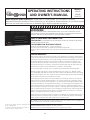
OPERATING INSTRUCTIONS
AND OWNER’S MANUAL
MODEL#
MHU50
MHU80
MHU125
READ INSTRUCTIONS CAREFULLY: YOUR SAFETY IS IMPORTANT TO YOU AND TO OTHERS.
Read and follow all instructions. Place instructions in a safe place for future reference. Do not allow anyone
who has not read these instructions to assemble, light, adjust or operate the heater.
Installer: Leave this manual with the appliance. Consumer: Retain this manual for future reference.
WARNING: Improper installation, adjustment, alteration, service or maintenance can cause
injury or property damage. Refer to this manual. For assistance or additional information
consult a qualified installer, service agency or the gas supplier.
-WHAT TO DO IF YOU SMELL GAS
ǞDO NOT try to light appliance.
ǞDO NOT touch any electrical switch, do not use any phone in your building
ǞLeave the building immediately
ǞImmediately call your gas supplier from a phone remote from the building. Follow the gas suppliers
instructions
ǞIf you cannot reach your gas supplier, call the Fire Department.
- Installation and service must be performed by a qualified installer, service agency or the gas supplier.
FOR YOUR SAFETY:
Do not store or use gasoline or other flammable vapors and liquids in the vicinity of this or any other appliance.
WARNING: If the information in these instructions are not followed exactly, a fire or explosion may result causing
property damage, personal injury or loss of life.
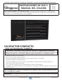
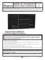
COMPACT UNIT HEATER
FOR RESIDENTIAL/COMMERCIAL USE
60185 REV C
www.mrheater.com • 800-251-0001

Compact Unit / Utility Heater 2Operating Instructions and Owner’s Manual
WARNING:
YOUR SAFETY IS IMPORTANT TO YOU AND TO OTHERS,
SO PLEASE READ THESE INSTRUCTIONS BEFORE YOU
OPERATE THIS HEATER.
WARNING:
FIRE OR EXPLOSION HAZARD
Failure to follow safety warnings exactly could result
in serious injury, death or property damage. Be sure to
read and understand the installation, operation, and
service in this manual. Improper installation, adjustment,
alteration, service or maintenance can cause serious
injury, death or property damage.
WARNING:
FIRE, BURN, INHALATION, AND EXPLOSION HAZARD.
KEEP SOLID COMBUSTIBLES, SUCH AS BUILDING
MATERIALS, PAPER, OR CARDBOARD, A SAFE DISTANCE
AWAY FROM THE HEATER. AS RECOMMENDED BY
THE INSTRUCTIONS NEVER USE THE HEATER IN SPACES
WHICH DO OR MAY CONTAIN VOLATILE OR AIRBORNE
COMBUSTIBLES, OR PRODUCTS SUCH AS GASOLINE,
SOLVENTS, PAINT THINNER, DUST PARTICLES OR
UNKNOWN CHEMICALS.
LANGUAGES
ENGLISH ..........................................................1 - 24
SPANISH ....................................................... 25 - 48
FRENCH ........................................................ 49 - 72
CONTENTS
PRODUCT SPECIFICATIONS ........................................... 3
MOUNTING DIMENSIONS ............................................. 4
SHIPPING ...................................................................... 5
REQUIREMENTS ............................................................ 5
UNIT HEATER INSTALLATION ........................................ 6
COMBUSTION & VENTILATION AIR .............................. 6
VENTING ...................................................................... 6
ELECTRICAL CONNECTIONS ........................................ 10
GAS CONNECTIONS ................................................... 11
LEAK CHECK ............................................................... 11
START-UP OPERATION ................................................ 11
HEATING SEQUENCE OF OPERATION ......................... 12
IGNITION CONTROL LED ............................................. 12
SERVICE ...................................................................... 13
WIRING DIAGRAM ..................................................... 14
FUEL CONVERSION ..................................................... 15
PARTS LIST ................................................................. 20
WARRANTY ................................................................ 24
GENERAL INFORMATION
RETAIN THIS MANUAL FOR FUTURE REFERENCE.
FOR QUESTIONS, PROBLEMS, MISSING PARTS BEFORE
RETURNING TO RETAILER PLEASE CALL WITH MODEL NUMBER
AND SERIAL NUMBER OF HEATER:
1-800-251-0001
MONDAY-FRIDAY 8-5 EASTERN TIME
OR E-MAIL USING THE MR. HEATER WEBSITE:
WWW.MRHEATER.COM
In order to provide the best service possible Mr. Heater is now
giving you more ways to get in touch with us:
FACEBOOK: Find us on Facebook
TWITTER: Find us on twitter
YouTube: There are now informational videos on Youtube.
WARNING:THIS PRODUCT CAN EXPOSE
YOU TO CHEMICALS INCLUDING LEAD AND LEAD
COMPOUNDS, WHICH ARE KNOWN TO THE STATE
OF CALIFORNIA TO CAUSE CANCER AND BIRTH
DEFECTS OR OTHER REPRODUCTIVE HARM. FOR MORE
INFORMATION VISIT WWW.P65WARNINGS.CA.GOV
WARNING: Fuels used in liquefied propane
gas appliances, and the products of combustion of such
fuel, can expose you to chemicals including benzene, which
is known to the state of California to cause cancer and
cause birth defects or other reproductive harm, for more
information go to www.P65Warnings.ca.gov

Compact Unit / Utility Heater 3Operating Instructions and Owner’s Manual
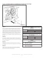
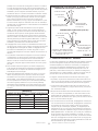
MHU125 MHU80 MHU50
V/A/H/Phase 120v / 3a / 60hZ / 1Ø 120v / 2.3a / 60hZ / 1Ø 120v / 2.3a / 60hZ / 1Ø
BTU Input 125,000 BTU 80,000 BTU 50,000 BTU
BTU Output 100,000 BTU 64,000 BTU 40,000 BTU
Efficiency % 80% 80% 80%
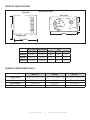
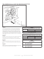
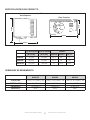
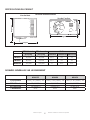
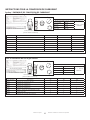
PRODUCT SPECIFICATIONS
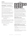
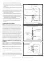
GENERAL PERFORMANCE DATA
Rear View
Width
Height
Length
Width
Dimensional Data
Top View
BTU input BTU output Size
[BTU/HR] [BTU/HR] WIDTH LENGTH HEIGHT
MHU50 50,000 40,000 25.5” 24” 13”
MHU80 80,000 64,000 25.5” 24” 18”
MHU125 125,000 100,000 27” 26.5” 25.5”

Compact Unit / Utility Heater 4Operating Instructions and Owner’s Manual
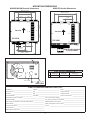
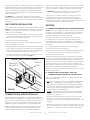
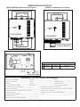
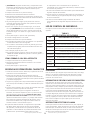
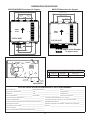
MOUNTING DIMENSIONS
FLUE OUTLET DIMENSION
MHU50 MHU80 MHU125
C 4.25” 6.75” 9.43”
ELECTRICAL INLETS
FLUE OUTLET
REAR VIEW
6” GAS INLET
C
START-UP AND PERFORMANCE CHECK LIST
Job Name: ___________________________ Job No.: _____________________________ Date: ___________________________
Job Location: _________________________ City: ________________________________ State/Province: ___________________
Installer: _____________________________ City: ________________________________ State/Province: ___________________
Unit Model No.: _______________________ Serial No.: ____________________________ Service Technician: ________________
Electrical Connections Tight? _____________________________ Flue Connections Tight? _________________________________
Supply Voltage ________________________________________ Fan Timer Operation Checked? ___________________________
Gas Piping Connections Tight & Leak-Tested? _______________ THERMOSTAT Calibrated? _______________________________
Motor Amps __________________________________________ Heat Anticipator Properly Set? ____________________________
Furnace BTU input _____________________________________ Level? _______________________________________________
Line Pressure _________________________________________
Manifold Pressure W.C. _________________________________
MHU50/MHU80 Bracket Dimensions MHU125 Bracket Dimensions
520mm (20.47")
320mm (12.6")
160mm
(6.3")
500mm (19.69")
310mm (12.2")
150mm
(5.9")
160mm
(6.3")
160mm
(6.3")
520mm (20.47")
320mm (12.6")
160mm
(6.3")
TOP VIEW TOP VIEW
AIR FLOW
AIR FLOW
Rear Bracket Identical
to Front Bracket

Compact Unit / Utility Heater 5Operating Instructions and Owner’s Manual
SHIPPING
The heater is completely assembled. Installation instructions, two
mounting brackets (shipped loose), and a flue transition are included.
Check the unit for shipping damage. The receiving party should
contact the last carrier immediately if any shipping damage is found.
REQUIREMENTS
REQUIREMENTS – CSA IN THE USA
Installation of gas unit heaters must conform with local building codes
or, in the absence of local codes, with the current National Fuel Gas
Code ANSI Z223.1.
Installation in aircraft hangers must be in accordance with the current
Standard for Aircraft Hangers ANSI/NFPA No. 409.
Installation in parking structures must be in accordance with the
current Standard for Parking Structures ANSI/NFPA No. 88A.
Installation in repair garages must be in accordance with the current
Standard for Repair Garages ANSI/NFPA No. 88B.
These units are approved for residential applications. For installation in
a residential garage these units must be installed so that the bottom
of the heater is located no less than 8 feet (2.438m) above floor.
Heater must be located or protected to avoid physical damage by
vehicles. Refer to the National Fuel Gas Code, ANSI Z223.1, current
edition.
Authorities having jurisdiction should be consulted before NFPA
installation. Air for combustion and ventilation must conform to the
methods outlined in ANSI Z223.1, section 5.3, Air for Combustion
and Ventilation, or applicable provisions of local building codes. The
National Fuel Gas Code is available from:
American National Standard Institute Inc.
11 West 42nd Street
New York, NY 10036
These units are CSA International design certified. These unit heaters
are certified for installation to combustible material as listed in table
1 and on unit rating plate. Accessibility and service clearances must be
observed in addition to fire protection clearances.
All electrical wiring and ground for unit must be in accordance with
the regulations of the current National Electric Code ANSI/No. 70.
The National Electric Code is available from:
National Fire Protection Association
1 Batterymarch Park
PO Box 9101
Quincy, MA 02269-9101
TABLE 1
UNIT CLEARANCES
Top Sides Access Panel
in mm in mm in mm
1 25 1 25 18 457
Bottom Rear
in mm in mm
0 0 18 456
REQUIREMENTS – CSA IN CANADA
The instructions are intended only as a general guide and do not
supersede local codes in any way. Authorities having jurisdiction
should be consulted before installation. The installation must conform
with local building codes or in the absence of local codes, with the
current CSA B149.1, Natural Gas and Propane Installation Code. All
electrical wiring and grounding for the unit must also comply with the
Canadian Electrical Code CSA C22.1, current edition.
These heaters are CSA International certified for the clearances to
combustible material listed on the rating plate and table1. Provide
adequate clearance around air openings into the combustion
chamber, clearances from combustible material, and provisions for
accessibility and for combustion and ventilation air supply. Provision
shall be made for service accessibility to the heater. Note that fire
protection clearances may be exceeded to provide additional space for
service and accessibility.
GARAGE INSTALLATIONS
Installation in parking structures must be in accordance with the
current Standard for Parking Structures ANSI/NFPA No. 88A.
Installation in repair garages must be in accordance with the current
Standard for Repair Garages ANSI/NFPA No. 88B.
1. In a storage area, clearance from heaters to combustible materials
must be such that the material shall not attain a temperature above
160°F by continuous operation of the unit.
2. Eight foot minimum clearance from the floor to the bottom of the
heater must be maintained. Refer to the CSA B149.1, Natural Gas
and Propane Installation Code.
AIRCRAFT HANGER INSTALLATIONS
Installation of gas unit heaters must conform with local building codes
or, in the absence of local codes, with the current National Fuel Gas
Code ANSI Z223.1.
1. In an area where aircraft are housed or serviced, 10’ minimum
clearance from highest surface of aircraft to bottom of the heater
must be maintained.
2. In other areas, 8’ minimum clearance from the floor to bottom of
heater must be maintained.
3. Heaters should be located so as to be protected from damage from
aircraft or other appliances needed for servicing of aircraft. Refer to
requirements of the enforcing authorities.

Compact Unit / Utility Heater 6Operating Instructions and Owner’s Manual
These units are certified for residential applications. For installation in
a residential garage, these units must be installed so that burners and
ignition source are located no less than 18” (457mm) above floor.
Heater must be located or protected to avoid physical damage by
vehicles. Refer to CSA B149.1, Natural Gas and Propane Installation
Code current edition.
IN CANADA: In a confined area, the heater must be installed in
accordance with the CSA B149.1, Natural Gas and Propane Installation
Code. Be sure to check with local codes and ordinances for additional
requirements.
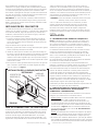
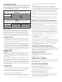
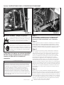
UNIT HEATER INSTALLATION
Unit is shipped ready for installation. Unit may be installed as shown in
figure 1 or inverted 180o depending on desired location as governed
by clearances, vent connection, air direction, gas supply, electrical
supply and service accessibility.
1. If installing unit in an inverted position: Remove and retain screws
securing door and rotate door 180o. Secure with retained screws.
Rotate louvers directing airflow as desired.
2. Choose location for mounting brackets.
3. Remove and retain three screws along top edge (bottom edge
when inverted) of front of unit.
4. Align screw holes on mounting bracket with holes along top edge
(either upright or inverted) of unit. Secure one mounting bracket to
front of unit with retained screws. Secure other mounting bracket
to back of unit with screws retained on the back of unit.
5. To support unit, secure mounting bracket to ceiling joist or truss.
Unit may also hang on rods as shown in figure 1.
INSTALL UNIT / UTILITY HEATER
FIGURE 1
MOUNTING
BRACKETS (2)
SUPPORT
RODS
COMBUSTION & VENTILATION AIR
Adequate facilities for supplying air for combustion and ventilation
must be provided in accordance with the latest edition of section 5.3,
Air for Combustion and Ventilation, of the National Fuel Gas Code,
ANSI Z223.1, in the U.S.A., CSA B149.1 Natural Gas and Propane
Installation Code, or applicable provisions of local building codes.
All gas fired appliances require air to be used for the combustion
process. In many buildings today, there is a negative indoor air
pressure caused by exhaust fans, etc. If sufficient quantities of
combustion air are not available, the heater or another appliance will
operate in an inefficient manner, resulting in incomplete combustion
which can result in the production of excessive carbon monoxide.
CAUTION:Insufficient combustion air can cause headaches,
nausea, dizziness, asphyxiation or death.
If indoor air is to be used for combustion, it must be free of the
following substances or the life of the heat exchanger will be
adversely affected: chlorine, carbon tetrachloride, cleaning solvent,
halogen refrigerants, acids, cements and glues, printing inks, fluorides,
paint removers, varnishes, or any other corrosives.
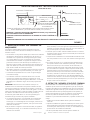
VENTING
A – GENERAL RECOMMENDATIONS AND REQUIREMENTS
NOTE: The vent is a passageway, vertical or nearly so, used to convey
flue gases from an appliance, or its vent connector, to the outside
atmosphere. The vent connector is the pipe or duct that connects a
fuel-gas burning appliance to a vent or chimney.
Unit heaters must be vented in compliance with all local codes
or requirements of the local utility, the current standards of the
(American) National Fuel Gas Code, ANSI Z223.1 or (Canada) CSA
B149.1 Natural Gas and Propane Installation Code, and the following
instructions.
Do not intermix different vent system parts from different
manufacturers in the same venting system.
Vent connectors serving Category I and Category II Appliances shall
not be connected into any portion of mechanical draft systems
operating under positive pressure.
A metal stamped/extruded transition is supplied with this certified
unit. It must not be modified or altered and must be installed on the
outlet of the induced draft blower assembly prior to the installation
of the vent or vent connector. Failure to comply with this requirement
will void the certification of the unit by the approval agencies. All
joints shall be secured with at least two corrosion resistant screws. All
joints must be checked for gas tightness after installation.
The heater and the venting system shall be inspected once a year by a
qualified service agency.
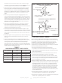
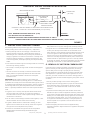
B – VERTICAL VENTS USING METAL VENT PIPE
– COMMERCIAL AND RESIDENTIAL INSTALLATIONS
MHU compact unit heaters are listed as Category I appliances for
vertical vent installations.
1. US: MHU unit heaters are to be used with NFPA- or ANSI-approved
chimneys, U.L. listed type B-1 gas vents, single wall metal pipe,
or listed chimney lining system for gas venting where applicable,
as well as the modifications and limitations listed in figure 2. Seal
single wall vent material according to the section A - General
Recommendations and Requirements.
Canada: Listed Category I Unit Heaters are to be used with Type
B gas vent. Minimum clearances of gas vent from combustible
material: 1 inch (25 mm)
2. The vent connector shall be 4”(102 mm) diameter on 50 & 80
& 125k units. In all cases, a flue transition piece (supplied) is
required to fit over the outlet of the induced draft assembly on the
appliance.
3. Keep the vent connector runs as short as possible with a minimum
number of elbows. Refer to the (American) National Fuel Gas Code
ANSI Z223.1 or (Canada) CSA B149.1 Natural Gas and Propane

Compact Unit / Utility Heater 7Operating Instructions and Owner’s Manual
Installation Code for maximum vent and vent connector lengths.
Horizontal run of the vent connector from the induced draft blower
to the chimney/vent cannot exceed the values in table 2.
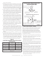
4. When the length of a single wall vent, including elbows, exceeds
5 feet (1.5m), the vent shall be insulated along its entire length
with a minimum of 1/2” thick foil faced fiberglass 1-1/2# density
insulation. If a single wall vent is used in an unheated area it shall
be insulated. Failure to do so will result in condensation of flue
gases.
5. The unit may be vented vertically as a single appliance or as a
common vent with other gas-fired appliances. In common venting
situations, vent connectors for other appliances must maintain a 4”
(100mm) vertical separation between the vent connectors. Refer to
common venting tables in the (American) National Fuel Gas Code
ANSI Z223.1 or (Canada) CSA B149.1 Natural Gas and Propane
Installation Code for proper vent size.
6. Clearance to combustible material is 6” (152mm) for single wall
vent material except where a listed clearance thimble is used.
Clearance to combustible material for type B-1 vent or factory-built
chimney is per manufacturer’s instructions.
7. The vent connector shall be supported without any dips or sags.
Vertical vents shall be supported in accordance with their listing and
manufacturers’ instructions. All horizontal vent connector runs shall
have a slope up to the vertical vent of at least 1/4” per foot (1mm
per 50mm).
8. All vertical type B-1 vents, single wall vents, or listed chimney lining
system must be terminated with a listed vent cap or listed roof
assembly.
9. The vent must extend at least 3’ (1m) above the highest point
where it passes through a roof of a building and at least 2’ (0.6m)
higher than any part of a building within a horizontal distance
of 10’ (3.05m) unless otherwise specified by the (American)
National Fuel Gas Code, ANSI Z223.1 or (Canada) CAN/CGA-B149
Installation Code. The vent must extend at least 5’ (1.6m) above the
highest connected equipment flue collar.
TABLE 2
MAXIMUM HORIZONTAL VENT LENGTHS
No. of Elbows Feet m
1 25 7.6
2 20 6.1
3 15 4.6
4 10 3.0
5 5 1.5
Maximum length of vent connector not to exceed 30 ft. (9.1m).
VENT TERMINATION ON SINGLE WALL VENT
ROOF FLASHING
ROOF PITCHED FROM
0° TO 45°
SHALL NOT BE A
CONCEALED SPACE
2” CLEARANCE
THIMBLE
ROOF FLASHING
ROOF PITCHED FROM
0° TO 45°
SEAL JOINT BETWEEN SINGLE WALL VENT
AND “B” VENT AND THE ANNULAR SPACE
OF THE “B” VENT
12” MAX
CLEARANCE TO BE AS
SPECIFIED ON TYPE “B”
VENT PIPE
FIGURE 2
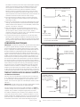
C – HORIZONTAL VENTING – GENERAL
Due to changes to Z83-8 2009 CSA2.6-2009, the use of single wall
B-Vent is no longer permitted as an acceptable material when venting
horizontally, this change covers both residential and commercial
installations. All horizontally vented units manufactured after July
of 2011 must be vented as a Caterory III Unit/Utility Heater in
compliance with UL 1738 & ULS636. Common venting is not allowed
when horizontally venting the unit heater.
The minimum horizontal vent length is 3 feet (914mm).
1. If possible, do not terminate the horizontal vent through a wall
that is exposed to prevailing wind. Exposure to excessive winds can
affect unit performance.
2. Vent termination must be free from obstructions and at least 12”
(306mm) above grade level and maximum snow height.
3. Do not terminate vent directly below roof eaves or above a walk-
way, or any other area where condensate dripping may be trouble-
some and may cause some staining. Avoid windows where steam
may cause fogging or ice buildup.
4. When horizontally vented, minimum clearance for termination from
any door, window, gravity air inlet, gas or electric meter, regulators,
and relief equipment is 4 ft. (1.2m) for U.S. installations. Refer to
NFPA 54/ANSI Z223.1 in the U.S.A. and CSA B149.1 Natural Gas
and Propane Installation Code and .2 in Canada or with authorities
having local jurisdiction. In Canada, vent termination must have a
minimum 6 ft. (1.8 m) horizontal clearance from gas and electric
meters and relief devices as specified in the Canadian B149.1, Natu-
ral Gas Installation Code.
5. Vent termination must be a minimum of 4’ (1.2m) below or 4’
(1.2m) horizontally from any soffit vent or under-eave vent.
6. Vent must be a minimum of 6’ from an inside corner formed by two
exterior walls. If possible, leave a 10’ clearance.
SINGLE WALL TERMINATION
DOUBLE WALL (TYPE B-1) TERMINATION

Compact Unit / Utility Heater 8Operating Instructions and Owner’s Manual
7. Vent termination must be a minimum of 10’ (3m) from any forced
air inlet (includes fresh air inlet for other appliances, such as a
dryer).
8. When termination is routed through an exterior combustible wall
the vent must be supported using a listed clearance thimble. Seal
the connection between the single wall and double wall pipes and
the annular space of the double wall pipe as shown in figure 2.
Inside edge of vent termination tee must be at least 12 inches from
outside wall as shown in figure 3.
9. For horizontal venting, the vent pipe shall be supported with
hangers no more than 3ft. (1m) apart to prevent movement after
installation.
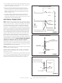
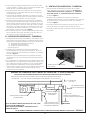
D – HORIZONTAL VENTING – COMMERCIAL
1. Horizontal commercial installations are for buildings which are not
attached to living spaces. The vent may be stainless steel sealed
single walled cat III vent material and must be installed according to
the sections
• A - General Recommendations and Requirements, and
• C - Horizontal Venting General, and
• D - Horizontal Venting - Commercial.
Refer to figure 3.
2. The vent pipe diameter for horizontal commercial installations shall
be 4” (76mm). a transition piece has been supplied and is already
attached to your heater. Refer to figure 4
3. Select a wall termination point that will maintain 1/4” rise per foot
slope of horizontal run of vent pipe.
4. For upward sloped vent a condensate tee and drain must be
installed within the first 5’ (1.5m) from the unit heater to protect
the appliance. If a flexible condensate drain line is used, the drain
line must include a loop entering the structure. If the unit is shut
down for an extended period of time and will be exposed to sub-
freezing temperatures, the condensate may freeze.
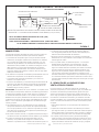
E – HORIZONTAL VENTING – RESIDENTIAL
1. For horizontal residential installations these units are certified as
Category III appliances. Venting A - General Recommendations and
Requirements and C - Horizontal Venting General and E - Horizontal
Venting - Residential. Refer to figure 5.
2. The vent pipe diameter for horizontal residential installations shall
be 4” on all units. A transition piece has been supplied and is
already attached to your heater. Refer to figure 4
3. The maximum vent length is 25’ (7.6m) plus one 90-degree elbow.
The minimum length is 5’(1.5m).
4. The vent must maintain a ¼1/4” rise per foot of slope (1mm per
50mm). upwards toward the termination.
Flue Transition (attached) FIGURE 4
CONDENSATE DRAIN THROUGH TEE PIPE AND DRAIN LOOP
UPWARD SLOPE ON HORIZONTAL VENT-COMMERCIAL INSTALLATION
CATEGORY III VENT ACCORDING TO THESE INSTALLATION INSTRUCTIONS.
SLOPE: +¼ INCH FOR 1 FOOT RUN MINIMUM (1mm per 50mm)
12 INCHES MIN
(30.5 CM)
EXHAUST VENT
TERMINATION TEE
12 INCHES MIN (30.5 CM)
MINIMUM ABOVE ALL
HIGHEST SNOWFALL
LISTED THIMBLE
THROUGH
COMBUSTIBLE WALL
DRAIN LOOP WITH WATER
TRAP (TO CONDENSATE DRAIN)
FLUE TRANSITION
(PROVIDED)
NOTE - MINIMUM HORIZONTAL LENGTH 3 FT. (1.5M)
NOT INCLUDING CAP FOR TERMINATION.
MAXIMUM HORIZONTAL LENGTH AND NUMBER OF ELBOWS
REFER TO TABLE 2.
FIGURE 3
COMMON VENTING NOT ALLOWED WHEN HORIZONTALLY VENTING THE UNIT / UTILITY HEATER

Compact Unit / Utility Heater 9Operating Instructions and Owner’s Manual
HORIZONTAL VENTING - RESIDENTIAL INSTALLATION
UPWARD SLOPE
CATEGORY III VENT ACCORDING TO THESE INSTALLATION INSTRUCTIONS.
SLOPE: +¼ INCH FOR 1 FOOT RUN MINIMUM (1mm per 50mm)
12 INCHES MIN
(30.5 CM)
VENT TERMINATION CAP
INDUCED DRAFT BLOWER
FLUE TRANSITION
(PROVIDED)
LISTED THIMBLE THROUGH
COMBUSTION WALL
NOTE - MINIMUM HORIZONTAL LENGTH 3FT. (1.5M)
NOT INCLUDING CAP FOR TERMINATION
MAXIMUM HORIZONTAL LENGTH AND NUMBER OF ELBOWS REFER TO TABLE 2
COMMON VENTING NOT ALLOWED WHEN HORIZONTALLY VENTING THE UNIT / UTILITY HEATER
FIGURE 5
F – VENTING USING A MASONRY CHIMNEY
The following additional requirements apply when a lined masonry
chimney is being used to vent the compact unit / utility heater.
1. Masonry chimneys used to vent Category I units heaters must
be either tile-lined or lined with a listed metal lining system or
dedicated gas vent. Unlined masonry chimneys are prohibited. A
category I appliance must never be connected to a chimney that is
servicing a solid fuel appliance. If a fireplace chimney flue is used
to vent this appliance, the fireplace opening must be permanently
sealed.
2. A fan assisted unit heater may be commonly vented into an existing
lined masonry chimney provided:
• The chimney is currently serving at least one draft-hood equipped
appliance.
• The vent connector and chimney are sized in accordance with
venting tables in the (American) National Fuel Gas Code ANSI
Z223.1 or (Canada) CSA B149.1 Natural Gas and Propane
Installation Code.
IMPORTANT Single appliance venting of a fan assisted unit
heater into a tile lined masonry chimney (interior or outside wall) is
prohibited. The chimney must first be lined with either type B-1 vent or
an insulated single wall flexible vent lining system, sized in accordance
with venting tables in the (American) National Fuel Gas Code ANSI
Z223.1 or (Canada) CSA B149.1 Natural Gas and Propane Installation
Code.
3. A type B-1 vent or masonry chimney liner shall terminate above
the roof surface with a listed cap or a listed roof assembly in
accordance with the terms of their respective listings and the vent
manufacturer’s instructions.
4. Do not install a manual damper, barometric draft regulator, or flue
restrictor between the unit heater and the chimney.
5. If type B-1 double-wall vent is used inside a chimney, no other
appliance can be vented into the chimney. Outer wall of type B-1
vent pipe must not be exposed to flue products.
6. Insulation for the flexible vent pipe must be an encapsulated
fiberglass sleeve recommended by the flexible vent pipe
manufacturer.
7. The space between liner and chimney wall should NOT be insulated
with puffed mica or any other loose granular insulating material.
8. If type B-1 vent or an insulated flexible vent pipe cannot be used
as liners, the chimney must be rebuilt to accommodate one of
these methods or some alternate approved method must be found
to vent the appliance. When inspection reveals that an existing
chimney is not safe for the intended purpose, it shall be rebuilt to
conform to nationally recognized standards, lined or relined with
suitable materials or replaced with a gas vent or chimney suitable
for venting unit heaters. The chimney passageway must be checked
periodically to ensure that it is clear and free of obstructions.
G –REMOVAL OF UNIT FROM COMMON VENT
In the event that an existing unit heater is removed from a venting
system commonly run with separate gas appliances, the venting
system is likely to be too large to properly vent the remaining
attached appliances. The following test should be conducted while
each appliance is in operation and the other appliances are not in
operation, yet remain connected to the common venting system. If
the venting system has been installed improperly, the system must be
corrected.
1. Seal any unused openings in the common venting system.
2. Visually inspect the venting system for proper size and horizontal
pitch. Determine there is no blockage or restriction, leakage,
corrosion, or other deficiencies which could cause an unsafe
condition.
3. If practical close all building doors and windows and all doors
between the space in which the appliances remaining connected
to the common venting system are located and other spaces of the
building. Turn on clothes dryers and any appliances not connected
to the common venting system. Turn on any exhaust fans, such
as range hoods and bathroom exhausts, so they will operate at
maximum speed. Do not operate a summer exhaust fan. Close
fireplace dampers.
4. Follow the lighting instructions. Place the appliance being
inspected in operation. Adjust thermostat so appliance will operate
continuously.

Compact Unit / Utility Heater 10 Operating Instructions and Owner’s Manual
5. Test for spillage at the draft hood relief opening after five minutes
of main burner operation. Use the flame of a match or candle, or
smoke from a cigarette, cigar, or pipe.
6. After it has been determined that each appliance remaining
connected to the common venting system properly vents when
tested as outlined above, return doors, windows, exhaust fans,
fireplace dampers and any other gas-burning appliance to their
previous condition of use.
7. If improper venting is observed during any of the above tests,
the common venting system must be corrected. The common
venting system should be re-sized to approach the minimum size as
determined by using the appropriate tables
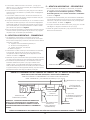
ELECTRICAL CONNECTIONS
NOTE: The MHU series unit/utility heaters use a direct spark ignition
system. There is no pilot necessary as the spark lights the main burner
as the gas valve is turned on. The direct spark ignition control board
emits radio noise during burner ignition. The level of energy may
be enough to disturb a logic circuit in a microprocessor controlled
thermostat. It is recommended that an isolation relay be used when
connecting the unit heater to a microprocessor controlled thermostat.
Select circuit protection and wire size according to the unit rating
plate. Install a separate disconnect switch (protected by either fuse
or circuit breaker) near the unit so that power can be turned off for
servicing. Remove electrical junction box cover and connect wiring
through knockout on the junction box located on the side of the
heater. Refer to heater wiring diagram for connection information.
Use 18 gauge wire or larger for line power connections. Make sure to
connect line power to wires located in the external electrical junction
box behind junction box cover. DO NOT CONNECT LINE POWER TO
THERMOSTAT TERMINAL STRIP ON OUTSIDE OF HEATER.
Electrically ground the unit in accordance with local codes or in the ab-
sence of local codes, in accordance with the current National Electrical
Code (ANSI/NFPA No. 70) in the USA, and in Canada with the current
Canadian Electrical Code, Part 1 CSA C22.1
NOTE: Un-insulated ground wire must be wrapped in electrical tape to
avoid damage to the electrical system.
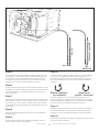
Make line voltage connections as shown in figure 6. Connect field
wiring as shown on wiring diagram on unit. Also, refer to typical
diagram in this manual.
To use the blower for air circulation only, your thermostat must have
a “fan only” or fan selection setting. In case your thermostat has this
option. an additional wire should be run to the “G” terminal on the
thermostat connection block. See wiring schematic on page 13.
UNIT
LINE VOLTAGE FIELD WIRING
L1
N
BLACK
BLACK
WHITE
WHITE
EQUIPMENT
GROUND
BLACK WIRE WITH WHITE TAPE
OR WHITE WIRE WITHOUT TAPE FIGURE 6
DRIP LEG
GROUNDED
JOINT UNION
MANUAL
MAIN SHUT-OFF VALVE
(FURNISHED BY INSTALLER)
GAS FLOW
GAS SUPPLY CONNECTION
FIGURE 7
UNIT HEATER
CAP
ISOLATE GAS
VALVE
MANUAL MAIN SHUT-OFF
VALVE WILL NOT HOLD
NORMAL TEST PRESSURE
GAS SUPPLY TO UNIT HEATER
FIGURE 8

Compact Unit / Utility Heater 11 Operating Instructions and Owner’s Manual
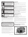
WARNING
Electric shock hazard. Can cause injury or death.
Do not use this heater if any part has been
under water. Immediately call a qualified service
technician to inspect the furnace and to replace
any part of the control system and any gas
control which has been under water.
WARNING
Electric shock hazard. Can cause injury or death.
Before attempting to perform any service or
maintenance, turn the electrical power to unit
OFF at disconnect switch(es). Unit may have mul-
tiple power supplies.
WARNING
Danger of explosion. Can cause injury or product
or property damage. If over-heating occurs or if
gas supply fails to shut off, shut off the manual
gas valve to the appliance before shutting off
electrical supply.
WARNING
Danger of explosion and fire. Can cause injury or
product or property damage. You must follow
these instructions exactly.
GAS CONNECTIONS
When connecting gas supply lines, the length of the piping run from
the meter to the heater must be considered in determining the pipe
size to avoid excessive pressure drop. A line pressure of 7” WC
(178mm WC) for natural gas should be maintained when sizing the
piping.
A line pressure of 13” WC (330mm WC) should be maintained for
propane (LP) gas. NOTE: Compounds used on threaded joints or gas
piping must be resistant to the actions of Liquefied petroleum gasses.
WARNING: TO PREVENT HEATER DAMAGE. WHEN USING A
PROPANE TANK TO SUPPLY HEATER, A MINIMUM 11”W.C.
LOW PRESSURE REGULATOR TO A MAXIMUM 14”W.C. LOW
PRESSURE REGULATOR IS REQUIRED. THIS REGULATOR
MUST BE INSTALLED BETWEEN THE TANK AND THE HEATER.
Regulator not supplied with heater.
For correct sizing of piping, refer to the (American) National Fuel Gas
Code ANSI Z223.1, or (Canada) CSA B149.1, National Gas and Pro-
pane Installation Code or consult the utility having jurisdiction.
A drip leg should be installed in the vertical pipe run to the unit. In
some localities, codes may require that a manual main shutoff valve
and union (furnished by installer) be installed external to the unit.
Union must be of the ground joint type. A drip leg should be readily
accessible to permit cleaning and empting. See figure 7.
NOTE: Leave a min of 4’’ clearance to the electrical connections box
on the back of the heater to allow for access.
A 1/8” NPT plugged tap shall be installed immediately upstream of the
gas supply connection to the heater. The purpose of this is to be able
to check for proper gas pressure entering the heater.
LEAK CHECK
CAUTION DO NOT use matches, candles, flame or other sources of
ignition to check for gas leaks.
After gas piping is completed, carefully check all piping connections,
(field and factory), for gas leaks. Use a soap solution or other pre-
ferred means.
Due to the natural heating cycles and vibration of this unit it is recom-
mended, as part of its annual maintenance, to check these connec-
tions for proper tightness and leak-check with a soap solution or other
preferred means prior to putting into service.
IMPORTANT The heater and its individual shut off valve must be
disconnected from the gas supply piping system during any pressure
testing of that system at test pressures in excess of 1/2 psig (3.45kPa).
The appliance must be isolated from the gas supply piping system by
closing its individual manual gas shutoff valve during any pressure
testing of the gas supply system at test pressures equal to or less than
1/2 psig (3.45kPa). See figure 8.
NOTE In case emergency shutdown is required, shut down main gas
valve and disconnect main power to unit. These devices should be
properly labeled by the installer.
START-UP OPERATION
UNIT START–UP
FOR YOUR SAFETY READ BEFORE LIGHTING
BEFORE LIGHTING smell all around the appliance area for gas. Be
sure to smell next to the floor because some gas is heavier than air
and will settle on the floor.
Use only your hand to move the gas control knob to the on position.
Never use tools. Do not use excessive force to switch valve from off to
on position. Force or attempted repair may result in a fire or explosion.
MHU 50/80/125 unit heaters are equipped with an automatic spark
ignition system. There is no pilot. In case of a safety shutdown, move
thermostat switch to OFF, then return the thermostat switch to HEAT
position.
Should overheating occur, or the gas supply fail to shut off, shut off
the manual gas valve to the appliance before shutting off the electrical
supply.
GAS VALVE OPERATION FOR HONEYWELL
VR8205M SERIES VALVE
MANIFOLD PRESSURE ADJUSTMENT
SCREW
(UNDER CAP)
GAS VALVE ROTARY SWITCH KNOB
MANIFOLD
PRESSURE
TAP
GAS
SUPPLY
INLET PRESSURE TAP
FIGURE 9

Compact Unit / Utility Heater 12 Operating Instructions and Owner’s Manual
1. STOP! Make sure you have read and understand all of the safety
information regarding the operation of this gas appliance. Any and
all service should be performed by a licensed installer
2. Set the thermostat to lowest setting.
3. Turn off all electrical power to appliance.
4. This appliance is equipped with an ignition device which
automatically lights burner. DO NOT attempt to light the burners
manually.
5. There is a black rotary switch knob that can be moved between the
on and off position. Rotate the switch knob to the off position. (See
Figure 9)
6. Wait five minutes to clear out any gas. If you then smell gas, STOP!
Immediately call your gas supplier from a neighbor’s phone. Follow
the gas supplier’s instructions. If you do not smell gas go to next
step.
7. Rotate the black switch knob to ON.
8. Turn on electrical power to unit.
9. Set the thermostat to desired setting.
10. The combustion air blower will start. The burners will light within
30 seconds.
11. If unit does not light first time (gas line not fully purged) it will
attempt up to two more ignitions before locking out.
12. If lockout occurs, repeat steps 1 through 9.
13. If appliance still will not operate, follow the instructions “TO TURN
OFF GAS TO UNIT” and call your service technician or gas supplier.
TO TURN OFF GAS TO UNIT
1. Set thermostat to lowest level.
2. Turn off all electrical power to unit if service is to be performed.
3. Rotate black knob to OFF position.
HEATING SEQUENCE OF OPERATION
1. When the thermostat calls for heat, the combustion air blower
starts immediately.
2. Combustion air pressure switch proves blower operation before
allowing power to the ignition controller. This switch is factory set
and no adjustment is necessary.
3. After pre-purge of approximately 30 seconds, the spark ignition is
energized and the solenoid valve opens in the gas valve.
4. The spark then ignites the gas, the ignition sensor proves the flame
and the combustion process continues.
5. In the event that the flame is not detected after the first 10-second
trial for ignition, the controller will repeat steps 3 and 4 an
additional two times before locking out the gas valve. Refer
to ignition control board table 3. Ignition control will then
automatically repeat steps 3, 4, and 5 after 60 minutes.
To interrupt the 60-minute lockout period, move thermostat from
“HEAT” to “OFF” then back to “HEAT.” Heating sequence then
restarts at step 1.
6. The burners shall light without noticeable crossover delay. There
shall be no flame lifting from the burner heads, flashback or
burning within the burner. The flames shall be predominantly blue
in color and shall be approximately centered in the tubes with no
apparent impingement taking place. If your burner characteristics
do not match those described above. Refer to the trouble shooting
sections.
7. The ignition control will energize the fan approximately 45 seconds
after ignition is established.
8. After the thermostat demand is satisfied the gas valve is closed; 5
seconds after the demand is satisfied the combustion air blower is
shut off.
9. The control center shall shut off the system fan approximately 150
seconds after the gas valve is de-energized.
IGNITION CONTROL LED
The ignition control board contains a green LED which indicates the
following: TABLE 3 IGNITION CONTROL LED
LED UNIT OPERATION
Slow Flash Normal Operation - No call for heat.
Fast Flash Normal Operation - Call for heat
Current signal at FLAME terminal 0.6 to 1.0 microamps
2 Flashes System lockout - failed to detect or sustain flame
Current signal at FLAME terminal <0.6 microamps
3 Flashes Pressure switch failed closed before CAB is energized or failed
open after CAB is energized
4 Flashes High limit or rollout switch open
5 Flashes Flame sensed and gas valve not energized
Steady Off Loss of power/Check 3AMP Fuse on circuit board
Steady On Ignition control failure
*When thermostat is placed in continuous fan mode LED will slowly
flash
LIMIT CONTROL
The limit control switch is factory set and not field adjustable.
LOUVER VANE ADJUSTMENTS
Rotate louver vanes to direct airflow upward, downward, straight,
or any combination of these directions. When unit is installed in an
inverted position, louvers may be positioned in the same manner.
COMBUSTION AIR PRESSURE SWITCH
This pressure switch checks for proper combustion air blower
operation before allowing an ignition trial. The switch is factory set
and no field adjustment is necessary. If a 3 flash LED occurs Please
make sure your venting is not blocked up. Next, remove the end of
the pressure switch tubing from the EXHAUST FAN hose barb. There
might be an obstruction in the hose barb opening clear out the
opening with a thin object that will fit inside the hose barb. Push that
through the length of the hose barb PLUS at least another 1/2 inch,
into the exhaust fan housing. This will clear out anything stopping the
vacuum from engaging the pressure switch.
FLAME ROLLOUT SWITCH
The flame rollout switch(es) are located on the burner box top, behind
the ignition control board. This normally closed switch opens on a
temperature rise. Check for adequate combustion air before manually
resetting switch.

Compact Unit / Utility Heater 13 Operating Instructions and Owner’s Manual
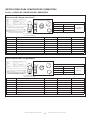
HIGH ALTITUDE
Units may be fired at full input up to 2000 ft. (610m) above sea level.
Above 2000 ft. (610m), manifold pressure must be adjusted on some
units. Adjust pressure regulator to pressure shown in table 4 for
natural gas and table 5 for LP/propane gas.
Table 4
NATURAL GAS MANIFOLD PRESSURES - IN. W.C.. (KPA)
MHU 50/80/125 ALTITUDE FT. (M)
0-2000 (0-610) 2000-4500 (610-1370)
MHU 50/80/125 4.0”WC (0.99 KPA)* 3.6”WC (0.89 KPA)
*NO ADJUSTMENT REQUIRED
Table 5
LP/PROPANE GAS MANIFOLD PRESSURES - IN.W.C.. (KPA)
MHU 50/80/125 ALTITUDE FT. (M)
0-2000 (0-610) 2000-4500 (610-1370)
MHU 50/80/125 10”WC (2.62 KPA)* 8.5”WC (2.12KPA)
*NO ADJUSTMENT REQUIRED
GAS FLOW
To check for proper gas flow to the combustion chamber, determine
the Btu input from the appliance rating plate. Divide this input rating
by the Btu per cubic feet of available gas. Result is the required
number of cubic feet per hour. Determine the flow of gas through the
gas meter for two minutes and multiply by 30 to get the hourly flow
of gas.
GAS PRESSURE
1. Check gas line pressure with unit firing at maximum rate. A
minimum of 5.0” w.c. for natural gas or 10.9” w.c. for LP/propane
gas should be maintained for proper unit operation.
2. After line pressure has been checked and adjusted, check manifold
pressure. Correct manifold pressure is shown on the unit rating
plate. See figure 9 for gas pressure adjustment screw location. A
natural gas to LP/propane gas changeover kit is required to convert
unit. Refer to installation instructions provided with changeover kit
for conversion procedure.
SERVICE
CAUTION Turn off gas and electrical power to unit before performing
any maintenance or service operations on this unit. Remember to
follow lighting instructions when putting unit back into operation after
service or maintenance.
If any of the original wire as supplied with the appliance must
be replaced, it must be replaced with wiring material having a
temperature rating of at least 105°C. Do not use this appliance if
any part has been under water. Immediately call a qualified service
technician to inspect the appliance and replace any gas control which
has been under water.
BURNERS
1. Periodically examine burner flames for proper appearance during
the heating season.
2. Before each heating season examine the burners for any deposits or
blockage that may have occurred.
3. Clean burners as follows:
• Turn off both electrical and gas supplies to unit.
• Disconnect gas supply piping, high tension and sensor leads.
Remove gas manifold. Remove burner tray.
• Clean burners as necessary. Make sure that burner heads line up
properly to ensure flame crossover. Check spark gap on electrode
and adjust if required. The gap should be between 0.110 inch and
0.140 inch (2.79mm to 3.56mm). The gap may be checked with
appropriately sized twist drills or feeler gauges.
• Reinstall burner tray, gas manifold, high tension and sensor leads.
Reconnect gas supply piping.
• Restore electrical power and gas supply. Follow lighting instructions
to light unit. Check burner flame.
FLUE PASSAGEWAY AND FLUE BOX
The flue passages and flue box should be inspected and cleaned prior
to each heating season. The sequence of operation should be as
follows:
1. Turn off both electrical and gas supply to unit.
2. Disconnect combustion air blower wiring.
3. Remove screws securing flue box to unit. Remove flue box. If
necessary, remove blower assembly from flue box. Clean flue box
with wire brush.
4. Remove turbulator retention bracket and turbulators. Clean
turbulators with wire brush.
5. Remove burners as described in section “BURNERS” section.
6. Clean tubes with a wire brush.
7. Reassemble unit. The combustion air and flue box gaskets should
also be replaced during reassembly.
8. Restore electrical power and gas supply. Follow lighting instructions
to light unit. Check operation of unit.
COMBUSTION AIR BLOWER
Under normal operating conditions, the combustion air blower should
be checked and cleaned prior to the heating season with the power
supply disconnected. Use a small brush to clean blower wheel.
ELECTRICAL
1. Check all wiring for loose connections.
2. Check for correct voltage at unit (unit operating).
3. Check amperage draw.
FLUE AND CHIMNEY
Check all vent and vent connector joints for tightness. Ensure that
connections are sealed and that there are no blockages.
FAILURE TO OPERATE
If unit fails to operate check the following:
1. Is thermostat calling for heat?
2. Is main disconnect closed?
3. Is there a breaker tripped or a fuse blown?
4. Is gas turned on at meter?
5. Is manual shutoff valve open?
6. Is unit ignition system in lock out? If unit locks out again, call service
technician to inspect unit.
7. Is pressure switch closed? Obstructed flue will cause unit to shut off
at pressure switch. Check flue passage and outlet.

Compact Unit / Utility Heater 14 Operating Instructions and Owner’s Manual
L1
ACB COOL
ACB HEAT
ACC LOW
ACC
ACC
HTG ACC
CWB BLWR
THERMOSTAT
24 VAC (HOT)
FLAME SENSOR
PSW RTN
PSW OUT
HIL RTN
HIL OUT
SPK ELE
VLV RTN
VLV OUT
GND
24 V POWER (R)
MAN BLOWER (G)
HEAT 1 (W1)
GND PRO THER
24 V (COMM) (C)
24V
120 V
Transformer
BlackWhite
Combustion Blower
BlackFan
White
Black
White
L1
(HOT)
N
(NEUTRAL)
EQUIPMENT
GROUND
Flame
Sensor
Flame Rollout
Switch
Air Switch
Red
Flame Rollout
Switch
Igniter
Gas Valve
Equipment Ground
Blue
Yellow
White
Blue
Black
Orange
Blue
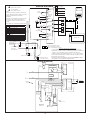
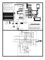
LADDER DIAGRAM
1
2
1
5
2
1
6
3
4
R
G
W
C
R
G
W
C
R
G
W
C
2
Red
White
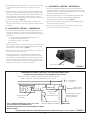
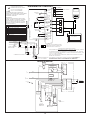
OPTIONAL THERMOSTAT INSTALLATION
IT IS RECOMMENDED TO USE 18AWG WIRE WHEN INSTALLING THE
THERMOSTAT. CONNECT ANALOG THERMOSTAT WIRING TO TERMINALS
‘R’ AND ‘W’ AS ILLUSTRATED ON THE SCHEMATIC DIAGRAM OR
CONNECT A DIGITAL/WiFi THERMOSTAT TO ‘R’ ‘W’ ‘C’ AS ILLUSTRATED.
NOTE: THERMOSTAT TERMINAL CONNECTIONS ARE MOUNTED ON THE
BACK PANEL OF THE HEATER.
EXTERNAL THERMOSTAT TERMINAL STRIP WANING: DO NOT CONNECT
LINE POWER TO THE THERMOSTAT TERMINAL STRIP.
24 Vac POWER
OPTIONAL FAN CONTROL
HEAT 1
COMMON
THERMOSTAT WIRING CONNECTOR ON HEATER
NOTE -
IF ANY WIRE IN THIS APPLIANCE IS REPLACED,
IT MUST BE REPLACED WITH WIRE OF LIKE SIZE,
RATING AND INSULATION THICKNESS.
WARNING -
ELECTRIC SHOCK HAZARD CAN CAUSE INJURY
OR DEATH. UNIT MUST BE GROUNDED IN
ACCORDANCE WITH NATIONAL AND LOCAL
CODES.
DISCONNECT ALL POWER BEFORE SERVICING!
MAXIMUM LOAD NOT TO EXCEED
20VA AT 24V, CLASS 2
(2) S47 USED IN
75, 80 AND 125 ONLY
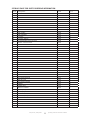
DESCRIPTION
KEY COMPONENT
A3 CONTROL BOARD (PCB)
B3 MOTOR CIRCULATION
B6 MOTOR-COMBUSTION AIR INDUCER
C4 CAPACITOR-BLOWER MOTOR 1
C5 CAPACITOR-INDUCED DRAFT MOTOR
DL36 RELAY-RELAY (N/A TO THESE MODELS)
GV1 VALVE-GAS
S10 SWITCH-PRIMARY GAS
S18 SWITCH-COMB AIR BLOWER
S47 SWITCH-FLAME ROLLOUT
T1 TRANSFORMER-CONTROL
BLACK
WHITE
CHASSIS GROUND
CONNECT CHASSIS
GROUND TO
EARTH GROUND
L1 CMB
BLWR ACC ACC
BLACK
WHITE
CAPACITOR USED IN 125 ONLY
C5
C4
BLACK
WHITE (COM)
GREEN
B3
B6
A3 LINE VOLTAGE FIELD INSTALLED
ANALOG THERMOSTAT WIRING
A3
GND
BLUE
YELLOW
GV1
SPARK
ELECTRODE
FLAME
SENSOR
BLUE
BROWN
(1)S47 (2)S47 ORANGE
24VAC
HOT
FLAME
1 TO 6
P1 ON BOARD
PRES. SW.
RETURN
PRES. SW.
OUT
HIGH LIMIT
SW. RETURN
HIGH LIMIT
SWITCH
OUT
GAS VLV
RETURN
GAS VLV
OUT
CAPACITOR USED IN
75, 80 AND 125 ONLY
S18
BROWN
RED
S10
WIRING DIAGRAM
120V
BLACK
BLUE
WHITE
GREEN / YELLOW 24V
Blue/Black
ANALOG
DIGITAL / WiFi
DIGITAL / WiFi THERMOSTAT WIRING

Compact Unit / Utility Heater 15 Operating Instructions and Owner’s Manual
FUEL CONVERSION
FUEL CONVERSION INSTRUCTIONS
FUEL CONVERSION Section 1: FUEL CONVERSION KITS
Fuel Conversion Part Numbers
Model # BTU/HR
Natural - To - LP
F260163
MHU 50 50,000
MHU 80 80,000
MHU 125 125,000
HONEYWELL KIT #393691
Orifice
(See P/N Table Below)
Gas Conversion Labels
For Converting from Natural Gas to L.P. Gas
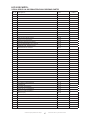
Part Number Description 50 80 125
13575 Gas conversion label 111
60232 Converted Rating tag 1
60233 Converted Rating tag 1
60234 Converted Rating tag 1
11727 Spring - gas valve (label inc.) 111
60156 L.P. Orifice 358
13576 Control Conversion Label 111
Control Conversion Labels
Fuel Conversion Part Numbers
Model # BTU/HR
LP - To - Natural
F260164
MHU 50 50,000
MHU 80 80,000
MHU 125 125,000
HONEYWELL KIT #393691
Orifice
(See P/N Table Below)
Gas Conversion Labels
For Converting from L.P. Gas to Natural Gas
Part Number Description 50 80 125
13575 Gas conversion label 111
60235 Converted Rating tag 1
60236 Converted Rating tag 1
60237 Converted Rating tag 1
11727 Spring - gas valve (label inc.) 111
60049 L.P. Orifice 358
13576 Control Conversion Label 111
Control Conversion Labels

Compact Unit / Utility Heater 16 Operating Instructions and Owner’s Manual
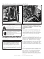
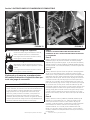
4 screws
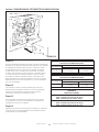
FUEL CONVERSION Section 2: FUEL CONVERSION INSTRUCTIONS
R
o
t
a
t
e
V
a
l
v
e
/
M
a
n
i
f
o
l
d
R
o
t
a
t
e
V
a
l
v
e
/
M
a
n
i
f
o
l
d
A
s
A
s
s
e
m
s
e
m
b
l
y
b
l
y
FIGURE 10 FIGURE 11
WARNING: Electrical Shock Hazard
Unplug the electrical cord from the outlet before
performing any service maintenance.
Failure to follow these instructions will result in death,
injury or property damage.
WARNING: Explosion Hazard
Turn off the gas supply to the heater before perform-
ing any service or maintenance.
Failure to follow these instructions will result in death,
injury or property damage.
The electrode and sensor are not adjustable. DO
NOT change location or position as part of this
conversion kit.
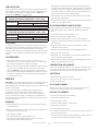
Step 1
CAUTION THE UNIT MUST NOT BE CONNECTED TO EITHER
THE GAS SUPPLY OR THE ELECTRICAL POWER SUPPLY, BEFORE
PROCEEDING WITH CONVERSION.
Step 2
Remove and retain the four screws holding the manifold on to the
burner box (Figure 10). Rotate the valve/ manifold assembly, away
from the burners (Figure 11). The valve/manifold assembly holds
the orifices (3 orifices on unit MHU50, 5 orifices on unit MHU80, 8
orifices on unit MHU125). This will allow access to the orifices on the
manifold, and also the adjustment spring in the valve/regulator.
Step 3
Remove and discard the adjustment spring cap from gas valve/
regulator with a flat blade screw driver by turning the screw counter-
clockwise. Remove and discard the regulator adjustment screw found
under the cap. Remove and discard the spring that is located under
the adjustment screw. Take the spring kit from the conversion kit,
and compare the part number of the kit to the parts list on page 14. If
it does not match, immediately contact Mr. Heater, Inc. for the correct
kit. After confirming the spring kit is correct for the heater model you
are converting, install the new spring and adjustment screw. Turn
spring adjustment screw clockwise (in) until the screw stops, then turn
it counter-clockwise (back) 1 ½ turns. Place conversion label supplied
with the spring kit on the valve near the adjustment screw cover
opening.
Step 4
Remove and discard the orifices (3 orifices on unit MHU50, 5 orifices
on unit MHU80, 8 orifices on unit MHU125) from the manifold with
using a ½ “ open end wrench. Turn them counter-clockwise to
remove. Take the new orifices from the conversion kit and before
installing, confirm that the number stamped on the side of the
orifice matches the number for the kit being installed. If it does not,
immediately contact Mr. Heater, Inc. for the correct kit. If they are
the correct orifices, install them in the manifold using caution not to
cross thread.
WARNING
This conversion kit shall be installed by a qualified service
agency in accordance with the manufacturer’s instructions
and all applicable codes and requirements of the authority
having jurisdiction. If the information in these instructions is
not followed exactly, a fire, explosion or production of carbon
monoxide may result causing property damage, personal injury
or loss of life. The qualified service agency performing this work
assumes responsibility for the proper conversion of this appliance
with this kit.

Compact Unit / Utility Heater 17 Operating Instructions and Owner’s Manual
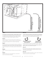
6
5
4
3
2
1
0
1
2
3
4
5
6
6
5
4
3
2
1
0
1
2
3
4
5
6
4” 10”
N.G. L.P.
FIGURE 12
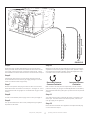
Step 5
Rotate the valve/ manifold assembly back up into the burner box,
making sure that all the orifices are indexed into the burners and are
not caught on the locating ring on the back of each burner. Secure
the manifold to the burner box with the four screws removed in step 2.
Step 6
Following the instructions in the unit heaters operations manual
mount the heater and connect the gas supply (making sure to leak
check all connections with soapy water).
Step 7
Remove valve pressure test plug and retain for later use. Connect a
water-filled U-tube manometer to the test port. See Figure 12. Use a
manometer because test gauges are not reliable and may give a false
reading.
Step 8
Connect main electrical power supply, and turn main gas supply on.
Step 9
Turn up the thermostat to call for heat, thereby starting the ignition
sequence for the heater.
Step 10
When the burners light, set the manifold gas pressure by turning the
adjustment screw to the regulator spring that was replaced in step 6.
Once the pressure has been adjusted, replace the adjustment screw
cover with a new one from the conversion kit.
Decrease Pressure
Counter-Clockwise
Increase Pressure
Clockwise
Refer to Table 6 for inlet pressure requirements, and set manifold
pressures according to gas type and altitude(See Table 4 and Table 5).
The manometer illustration (See Figure 12) shows each of the pressure
readings.
Step 11
Turn down the thermostat and allow the heater to complete a cool
down cycle. Then disconnect main electrical power, and turn the
main gas supply off to appliance.
Step 12
Disconnect the manometer from appliance and replace the test plug
on valve removed in step 6.

Compact Unit / Utility Heater 18 Operating Instructions and Owner’s Manual
FUEL CONVERSION Section 3: RATE TAG CONVERSION INSTRUCTIONS
FIGURE 13
Step 13
Connect main electrical power, and turn main gas supply back on.
Turn up thermostat to call for heat. When the main burners light
using soapy water check all connections thoroughly for gas leaks.
Remembering to also check the pressure test plug replaced in step
12. Allow the heater to operate for at least 5 minutes, then observe
the main burner flame. A hard blue flame extending into the tube is
normal. Slight yellow tipping is acceptable. There is no air adjustment
to the burner.
Step 14
See figure 13. Remove the data tag for their respective gases. Remove
label and place over the existing portion of the tag. This tag is
preprinted with all the correct information for the converted heater.
Step 15
Remove the converted information tag from the kit and fill in the
information. Then place this tag below the updated rating tag on the
unit.
Step 16
Replace any panels and operate heater following all warnings/cautions
and instructions in the operator’s manual and labels.
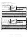
Table 4
NATURAL GAS MANIFOLD PRESSURES - IN. W.C.. (KPA)
MHU 50/80/125 ALTITUDE FT. (M)
0-2000 (0-610) 2000-4500 (610-1370)
MHU 50/80/125 4.0”WC (0.99 KPA)* 3.6”WC (0.89 KPA)
*NO ADJUSTMENT REQUIRED
Table 5
LP/PROPANE GAS MANIFOLD PRESSURES - IN.W.C.. (KPA)
MHU 50/80/125 ALTITUDE FT. (M)
0-2000 (0-610) 2000-4500 (610-1370)
MHU 50/80/125 10”WC (2.49 KPA)* 8.5”WC (2.12KPA)
*NO ADJUSTMENT REQUIRED
Table 6
INLET PRESSURES:
Natural Gas
MAX - 14” WC (3.49 kPa)
MIN - 5”WC (1.25 kPa)
Propane
MAX - 14” WC (3.49 kPa)
MIN - 11”WC (2.74 kPa)

Compact Unit / Utility Heater 19 Operating Instructions and Owner’s Manual
THIS PAGE INTENTIONALLY LEFT BLANK
ESTA PÁGINA SE DEJÓ INTENCIONALMENTE EN BLANCO
CETTE PAGE A ÉTÉ INTENTIONNELLEMENT LAISSÉE VIERGE

Compact Unit / Utility Heater 20 Operating Instructions and Owner’s Manual
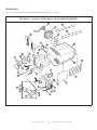
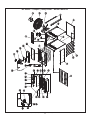
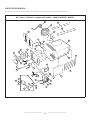
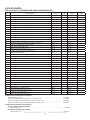
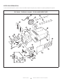
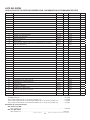
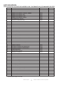
REPAIR PARTS
When ordering parts include the complete unit model number listed on the unit rating plate.
Mr. Heater • Compact / Utility Heater • Model # MHU50 / MHU80
30
31
19
20
28
22
21
27
2
4
3
5
6
7
12
8
9
34
11
10
35
15
13
16
17 18
14
23 24
26 32
38
36
37
25
1
29
La page est en cours de chargement...
La page est en cours de chargement...
La page est en cours de chargement...
La page est en cours de chargement...
La page est en cours de chargement...
La page est en cours de chargement...
La page est en cours de chargement...
La page est en cours de chargement...
La page est en cours de chargement...
La page est en cours de chargement...
La page est en cours de chargement...
La page est en cours de chargement...
La page est en cours de chargement...
La page est en cours de chargement...
La page est en cours de chargement...
La page est en cours de chargement...
La page est en cours de chargement...
La page est en cours de chargement...
La page est en cours de chargement...
La page est en cours de chargement...
La page est en cours de chargement...
La page est en cours de chargement...
La page est en cours de chargement...
La page est en cours de chargement...
La page est en cours de chargement...
La page est en cours de chargement...
La page est en cours de chargement...
La page est en cours de chargement...
La page est en cours de chargement...
La page est en cours de chargement...
La page est en cours de chargement...
La page est en cours de chargement...
La page est en cours de chargement...
La page est en cours de chargement...
La page est en cours de chargement...
La page est en cours de chargement...
La page est en cours de chargement...
La page est en cours de chargement...
La page est en cours de chargement...
La page est en cours de chargement...
La page est en cours de chargement...
La page est en cours de chargement...
La page est en cours de chargement...
La page est en cours de chargement...
La page est en cours de chargement...
La page est en cours de chargement...
La page est en cours de chargement...
La page est en cours de chargement...
La page est en cours de chargement...
La page est en cours de chargement...
La page est en cours de chargement...
La page est en cours de chargement...
-
 1
1
-
 2
2
-
 3
3
-
 4
4
-
 5
5
-
 6
6
-
 7
7
-
 8
8
-
 9
9
-
 10
10
-
 11
11
-
 12
12
-
 13
13
-
 14
14
-
 15
15
-
 16
16
-
 17
17
-
 18
18
-
 19
19
-
 20
20
-
 21
21
-
 22
22
-
 23
23
-
 24
24
-
 25
25
-
 26
26
-
 27
27
-
 28
28
-
 29
29
-
 30
30
-
 31
31
-
 32
32
-
 33
33
-
 34
34
-
 35
35
-
 36
36
-
 37
37
-
 38
38
-
 39
39
-
 40
40
-
 41
41
-
 42
42
-
 43
43
-
 44
44
-
 45
45
-
 46
46
-
 47
47
-
 48
48
-
 49
49
-
 50
50
-
 51
51
-
 52
52
-
 53
53
-
 54
54
-
 55
55
-
 56
56
-
 57
57
-
 58
58
-
 59
59
-
 60
60
-
 61
61
-
 62
62
-
 63
63
-
 64
64
-
 65
65
-
 66
66
-
 67
67
-
 68
68
-
 69
69
-
 70
70
-
 71
71
-
 72
72


Mr. Heater F260550 Le manuel du propriétaire
- Catégorie
- Chauffe-eau
- Taper
- Le manuel du propriétaire
dans d''autres langues
Autres documents
-
HeatStar HSU80NG Le manuel du propriétaire
-
HeatStar 8944969 Le manuel du propriétaire
-
-
Modine Manufacturing HDS Series Heaters Installation & Service Manual
-
Modine HDS125AS0111FBA Guide d'installation
-
Rheem ECOH180XELP-1 Manuel utilisateur
-
 Lennox Hearth Gas Stove Manuel utilisateur
-
Laars JVS160P Guide d'installation
-
Rinnai RUS65EP Manuel utilisateur
-
Rinnai REU-KCM2025W-US-N Guide d'installation
