Honeywell RCHT8610WF Guide d'installation
- Catégorie
- Thermostats
- Taper
- Guide d'installation

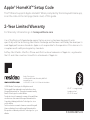
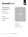
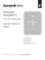
T5 Smart
Thermostat
Programmable
Thermostat
Quick Install Guide
For more information visit honeywellhome.com
Mode
Menu Fan
Mode Fan
Heat Auto
Wake Away Home Sleep
Following Schedule
RCHT8610WF,
RCHT8612WF,
RTH8800WF,
Read before installing

2 3
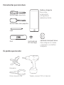
Included in your box:
Screws and
anchors
UWP™
Mounting
System
(UWP)
T5 Smart
Thermostat
Quick Install
uide

2 3
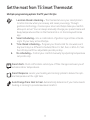
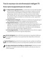
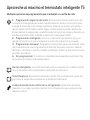
Multiple programming options that fit your lifestyle:
1. LocationBased scheduling – The thermostat uses your smartphone’s
location to know when you’re away, and saves you energy. Through
geofence technology, it senses your return and helps make you comfort-
able upon arrival. You can always manually change your preset Home and
Away temperature either on the thermostat or on the Honeywell Home
app.
2. Smart scheduling – Use a combination of geofencing and time schedul-
ing to fit your busy, active lifestyle.
3. TimeBased scheduling – Program your thermostat for one week; each
day (each day is a different schedule); MonFri, Sat, Sun; or MonFri, Sat-
Sun. All days with four adjustable periods per day.
4. No scheduling – Control your comfort manually by adjusting temperature
set points only.
Smart Alerts. Push notifications remind you of filter changes and warn you of
extreme indoor temperatures.
Smart Response. Learns your heating and cooling system to deliver the opti-
mal temperature at the right time.
Auto Change From Heat to Cool. Automatically determine if your home needs
heating or cooling to provide maximum comfort.
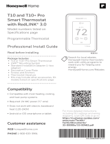
Get the most from T5 Smart Thermostat
!

4
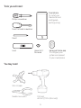
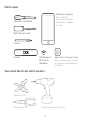
Tools you will need:
You may need:
Wire stripper
Needle-nose pliers Drill and
drill bit (7/32 in (5.6 mm))
Smartphone
To install your
thermostat and
photograph
existing wiring.
Honeywell Home app
To configure your
system and connect
to your smartphone.
Small flat head scr
ewdriver
Phillips scr
ewdriver
Pencil
Le
velHome Wi-Fi
Password

4 5
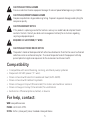
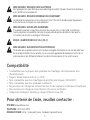
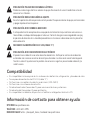
Compatibility
• Compatible with most heating, cooling, and heat pump systems
• Required: 24 VAC power (“C” wire)
• Does not work with electric baseboard heat (120240V)
• Does not work with millivolt systems
• Does not support input (S terminals) for indoor and outdoor sensors
• Does not support relay (U terminals) for ventilation
• Android or iOS smartphone, tablet, or device
For help, contact:
WEB honeywellhome.com
PHONE 18006333991
SOCIAL Twitter: @Honeywell_Home, Facebook: Honeywell Home
CAUTION: MERCURY NOTICE
If this product is replacing a control that contains mercury in a sealed tube, do not place the old
control in the trash. Contact your local waste management authority for instructions regarding
recycling and proper disposal.
CAUTION: EQUIPMENT DAMAGE HAZARD
Compressor protection is bypassed during testing. To prevent equipment damage, avoid cycling the
compressor quickly.
CAUTION: ELECTRICAL HAZARD
Can cause electrical shock or equipment damage. Disconnect power before beginning installation.
REQUIRED: 24 VAC POWER (“C” WIRE)
CAUTION: ELECTRONIC WASTE NOTICE
The product should not be disposed of with other household waste. Check for the nearest authorized
collection centers or authorized recyclers. The correct disposal of end-of-life equipment will help
prevent potential negative consequences for the environment and human health.

6 7
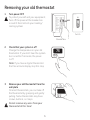
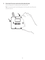
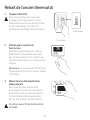
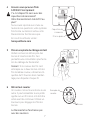
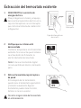
Removing your old thermostat
2 Check that your system is off
Change the temperature on your old
thermostat. If you don’t hear the system
turn on within 5 minutes, the power
is off.
Note: If you have a digital thermostat
that has a blank display, skip this step.
1 Turn power OFF
To protect yourself and your equipment,
Turn off the power at the breaker box
or switch that controls your heating/
cooling system.
3 Remove your old thermostat from the
wall plate
On most thermostats, you can take off
the thermostat by grasping and gently
pulling. Some thermostats may have
screws, buttons, or clasps.
Do not remove any wires from your
thermostat at this time!
75
OFF
OFF
ON
OFF
OFF
ON
75
Breaker box
Switch

6 7
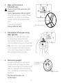
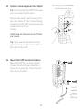
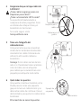
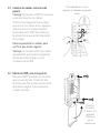
5 Take a picture of how your wiring
looks right now
Be sure to include the letters next
to the terminals where the wires
are inserted. This will be a helpful
reference when wiring your thermostat.
Tip: If the color of your wires has faded
or if 2 terminals have the same wire
color, use the wire labels provided in
the package to label each wire.
4 Make sure there are no
120/240V wires
Do you have thick black wires with
wire nuts?
Is your thermostat 120V or higher?
If you answered yes to either of these
questions, you have a line voltage
system and the thermostat will not
work.
If you are unsure visit:
honeywellhome.com
6 Remove any jumpers
A jumper connects one terminal to
another terminal. It may look like a
small staple or even a colored wire and
must be removed before continuing.
Use a screwdriver to release wires from
terminals.
The thermostat does not
need jumpers.
YRRC
Example of
a jumper
Wire nut
Thick black wire
Terminals
1/4” to 3/8”

8 9
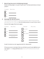
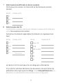
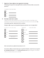
7 Record if you have wires in the following terminals
Do not include jumpers as a part of your count. The thermostat does not need
jumpers.
Terminal Wire Color
R
Rh
Rc
8 Write down the color of the wires
Check mark the wires that are connected to terminals. Next to the check mark,
write down the color of the wire. Do not include jumpers as a part of your count.
Check all that apply (Not all will apply):
Terminal Wire Color
Y
Y2
G
C
Terminal Wire Color
A or L/A
O/B
W2 or AUX
E
W
K
Required
S and U terminals are not supported with this thermostat.
If there are wires in terminals that are not listed, you will need additional wir-
ing support. Visit honeywellhome.com to find out if the thermostat will work
for you.

8 9
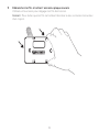
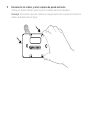
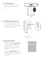
9 Disconnect the wires and remove the old wall plate
Use a screwdriver to release wires from terminals.
Tip: To prevent wires from falling back into the wall, wrap the wires
around a pencil.

10
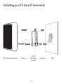
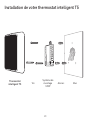
Installing your T5 Smart Thermostat
T5 Smart Thermostat Screws UWP
Mounting
System Anchors Wall

10 11
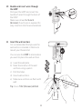
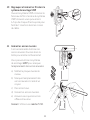
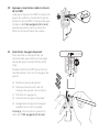
11 Insert the wall anchors
It is recommended that you use the
wall anchors included in the box to
mount your thermostat.
You can use the UWP to mark where
you want to place the wall anchors.
a) Level the wall plate.
b) Mark the location of the wall
anchors using a pencil.
c) Drill the holes.
d) Insert wall anchors.
e) Make sure anchors are flush with
wall.
Tip: Use a 7/32 (5.6 mm) drill bit.
10 Bundle and insert wires through
the UWP
Pull open the UWP and insert the
bundle of wires through the back of
the UWP.
Make sure at least 1/4-inch
(6.4 mm) of each wire is exposed for
easy insertion into the wire terminals.

12
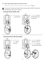
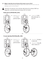
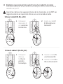
12 Set R-switch position and insert R-wire or wires
Set the R-switch up or down based on your wiring notes in Step 7.
Insert wires into the inner holes of the terminals on the UWP. The tabs will
stay down once the wire is inserted.
If you have 1 R-wire (R, Rh, or Rc)
If you have 2 R-wires (R or Rh, and Rc)
or
1. Set R-switch to
the up position.
1. Set R-switch
to the down
position.
2. Insert your R-wire
(R, Rh or Rc) into
R-terminal.
2. Insert your Rc wire
into Rc-terminal.
3. Insert your R or Rh
wire into RTerminal.

12 13
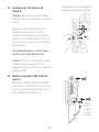
13 Connect remaining wires from Step 8
Tip: Do not mount the UWP to the wall
prior to connecting the wires.
Depress the tabs to put the wires into
the inner holes of their corresponding
terminals on the UWP (one wire per ter-
minal) until it is firmly
in place.
Gently tug on the wires to verify they
are secure.
Tip: If you need to release the wires
again, push down the terminal tabs on
the sides of the UWP.
14 Mount the UWP and close the door
Mount the UWP using the provided
screws. Install all three screws for a
secure fit on your wall. Close the door
after you’re finished.
This wiring is just an example,
actual wiring may vary.
Use 3x
supplied
screws
#8 11/2”
(38.1 mm)
1/4” to 3/8”

14 15
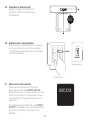
16 Turn your power ON
Turn on the power at the breaker box
or switch that controls the heating/
cooling system.
OFF
ON
ON
OFF
ON
ON
90o
15 Attach your thermostat
Align the thermostat onto the
UWP and firmly snap it into place.
17 Return to the thermostat
Return to the thermostat. Confirm the
screen shows START SETUP. If it does,
continue to “Setup with Honeywell
Home App” on page 15.
If your thermostat does not show
START SETUP, please contact
Resideo support.
Breaker box
Switch

14 15
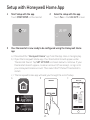
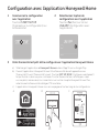
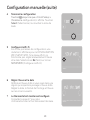
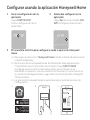
1 Start Setup with the app
Touch START SETUP on thermostat.
Setup with Honeywell Home App
No
Yes
Back
2 Select to setup with the app
Touch Yes on the USE APP screen.
3 Your thermostat is now ready to be configured using the Honeywell Home
app
a.) Download the “Honeywell Home” app from the App store or Google play.
b.) Open the Honeywell Home app. Your thermostat should appear under
Thermostat Found. Tap SET UP NOW as shown below to continue. If your
thermostat doesn’t appear, create an account (if necessary), or sign in to
your Honeywell Home account. Then select the T5 Smart Thermostat to
install.
c.) The Honeywell Home app will walk you through the rest of setup.
A B C
Thermostat Found:
SET UP NOW

16 17
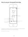
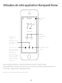
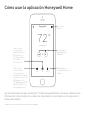
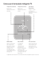
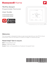
How to use your Honeywell Home App
SCHEDULEFANMODE
72˚
FOLLOWING SCHEDULE
72˚
MY HOME
Thermostat Access the
menu
Set desired
temperature
Schedule your home
comfort
Select System
mode Auto/Heat/
Cool/Off/EM Heat
Select Fan mode
Auto/On/Circulate.
Interested in more Resideo products? Visit honeywellhome.com to learn about all
available products connected by the Honeywell Home App.
App is regularly enhanced and may change.

16 17
Mode
Menu Fan
Mode Fan
Heat Auto
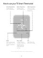
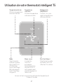
How to use your T5 Smart Thermostat
The screen will wake up by touching the center area of displayed temperature.
Mode
Select system mode
Auto/Heat/Cool/Off/
EM Heat (emergency
heat).
Menu
Contains features:
schedule, screen lock,
ventilation, WiFi,
clean screen, and
other thermostat
settings.
Fan
Select Fan mode
Auto/On/Circulate.
Desired temperature
Displays desired
indoor temperature.
Indoor Temperature
Displays current
indoor temperature.
Adjust temperature
Touch + or - to set
your desired indoor
temperature.

18 19
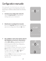
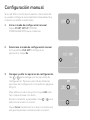
If your WiFi network is not working, you can
alternatively setup your thermostat manually
and connect your phone later.
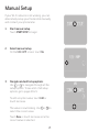
1 Start manual setup
Touch START SETUP to begin.
Manual Setup
Edit
No
Yes
3 Navigate and edit setup options
Use or to navigate through all the
setup options. To see a list of all setup
options, go to pages 2021.
To edit an option value, touch Edit or
touch text area.
The value is now blinking. Use or to
select the correct value.
Touch Done or touch text area once the
correct value is selected.
2 Select manual setup
On the USE APP screen, touch No.

18 19
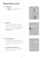
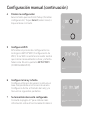
4 Finish Setup
Touch until you see Finish Setup.
Touch Select or touch text area.
Manual Setup (cont.)
Select
No
Yes
Back
No
Yes
Back
5 Setup WiFi
At the end of setup process you will be
prompted to SETUP WIFI. If your WiFi
is still not working, you have to manually
set the time and date. Select No on the
SETUP WIFI screen.
6 Set time and date
Set daylight saving time if you are in an
area that follows daylight saving time. Set
date, clock format and time on the next
screens.
7 Your thermostat is now setup
Refer to page 17 for more information
about basic operation.

20 21
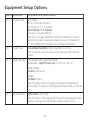
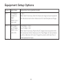
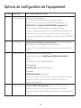
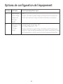
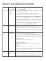
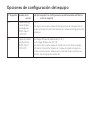
Equipment Setup Options
Option # Option Name Option Value (factory default in bold)
120 Schedule Type No Schedule
MOSU = Every day the same
MOFR SA SU = 511 schedule
MO-FR SA-SU = 5-2 schedule
Each Day = Every day different
Note: You can change default MO-FR, SA-SU schedule here. To edit
periods during days, temperature setpoints, or to turn Schedule On/
Off, touch MENU from the Home screen and go to SCHEDULE.
200 System Type Conventional Forced Air, Heat Pump, Boiler, Cool Only
Note: This option selects the basic system type your thermostat will
control.
205 Equipment Type Conventional Forced Air Heat:
Standard Gas, High Efficiency Gas, Oil, Electric, Fan Coil
Heat Pump:
Air to Air, Geothermal
Boiler:
Hot Water, Steam
Note: This option selects the equipment type your thermostat will
control. Note: This feature is NOT displayed if feature 200 is set to Cool
Only.
218 Reversing Valve O/B on Cool, 0/B on Heat
Note: This option is only displayed if the Heat Pump configured. Select
whether reversing valve O/B should energize in cool or in heat.
La page est en cours de chargement...
La page est en cours de chargement...
La page est en cours de chargement...
La page est en cours de chargement...
La page est en cours de chargement...
La page est en cours de chargement...
La page est en cours de chargement...
La page est en cours de chargement...
La page est en cours de chargement...
La page est en cours de chargement...
La page est en cours de chargement...
La page est en cours de chargement...
La page est en cours de chargement...
La page est en cours de chargement...
La page est en cours de chargement...
La page est en cours de chargement...
La page est en cours de chargement...
La page est en cours de chargement...
La page est en cours de chargement...
La page est en cours de chargement...
La page est en cours de chargement...
La page est en cours de chargement...
La page est en cours de chargement...
La page est en cours de chargement...
La page est en cours de chargement...
La page est en cours de chargement...
La page est en cours de chargement...
La page est en cours de chargement...
La page est en cours de chargement...
La page est en cours de chargement...
La page est en cours de chargement...
La page est en cours de chargement...
La page est en cours de chargement...
La page est en cours de chargement...
La page est en cours de chargement...
La page est en cours de chargement...
La page est en cours de chargement...
La page est en cours de chargement...
La page est en cours de chargement...
La page est en cours de chargement...
La page est en cours de chargement...
La page est en cours de chargement...
La page est en cours de chargement...
La page est en cours de chargement...
La page est en cours de chargement...
La page est en cours de chargement...
La page est en cours de chargement...
La page est en cours de chargement...
La page est en cours de chargement...
La page est en cours de chargement...
La page est en cours de chargement...
La page est en cours de chargement...
-
 1
1
-
 2
2
-
 3
3
-
 4
4
-
 5
5
-
 6
6
-
 7
7
-
 8
8
-
 9
9
-
 10
10
-
 11
11
-
 12
12
-
 13
13
-
 14
14
-
 15
15
-
 16
16
-
 17
17
-
 18
18
-
 19
19
-
 20
20
-
 21
21
-
 22
22
-
 23
23
-
 24
24
-
 25
25
-
 26
26
-
 27
27
-
 28
28
-
 29
29
-
 30
30
-
 31
31
-
 32
32
-
 33
33
-
 34
34
-
 35
35
-
 36
36
-
 37
37
-
 38
38
-
 39
39
-
 40
40
-
 41
41
-
 42
42
-
 43
43
-
 44
44
-
 45
45
-
 46
46
-
 47
47
-
 48
48
-
 49
49
-
 50
50
-
 51
51
-
 52
52
-
 53
53
-
 54
54
-
 55
55
-
 56
56
-
 57
57
-
 58
58
-
 59
59
-
 60
60
-
 61
61
-
 62
62
-
 63
63
-
 64
64
-
 65
65
-
 66
66
-
 67
67
-
 68
68
-
 69
69
-
 70
70
-
 71
71
-
 72
72


Honeywell RCHT8610WF Guide d'installation
- Catégorie
- Thermostats
- Taper
- Guide d'installation
dans d''autres langues
Documents connexes
-
Honeywell RCHT8610WF Guide d'installation
-
Honeywell RCHT8612WF20052PK Manuel utilisateur
-
Honeywell RCHT9610WFSW2003/U Guide d'installation
-
-
-
Honeywell THX321WFS2001W Mode d'emploi
-
-
Autres documents
-
 Honeywell Home RTH Series T5 Smart Thermostat Guide d'installation
-
Honeywell Home T6 Mode d'emploi
-
Honeywell Home RCHT8610WF Manuel utilisateur
-
 Honeywell Home THX321WFS2001W Guide d'installation
-
resideo RTH8800WF2022/U Une information important
-
 Honeywell Home TH6320WF2003/U Mode d'emploi
-
ecobee 55470766937 Manuel utilisateur
-
Bryant ecobee3 Lite Mode d'emploi
-
Bryant Smart thermostat Mode d'emploi
-
Nomadix ALERTS-SB1 Mode d'emploi


