Honeywell AQ3STF Sulfur Dioxide Gas so2 Sensor Mode d'emploi
- Taper
- Mode d'emploi

CONTENTS
Document Purpose
The Gas Response Curve
Linearity
Temperature Characteristics
Variation of Sensitivity with Temperature
Variation of SO2 Reading with Temperature after Compensation
Variation of Baseline Offset with Temperature after Compensation
Long-term Sensitivity Drift
Repeatability
Calibration Guidelines
Recommended Gas Flow Rates
Recommended Circuit
Compensation Logics of AQ3 Series Sensors
Cross Sensitivity Table
CHARACTERIZATION
NOTE
AQ3STF Sulfur Dioxide Gas Sensor
DOCUMENT PURPOSE
The purpose of this document is
to provide indicative, technical
performance data for the AQ3STF
gas sensor to assist in the
integration of the sensor into gas
detection instrumentation. The
sensor has been subjected to a
testing program as part of the
development process. Within this
document, detailed information
on the results of this program is
presented. All data has been taken
from equipment using a +5 Vdc
power supply.
This document and the information
contained within does not
constitute a specification. The
data is provided for informational
purposes only and is not warranted
by the manufacturer. It should be
used in conjunction with the AQ3
Product Datasheet, Operating
Principles(OP20) and the Product
Safety Datasheet (PSDS 19).
, NOTICE
• Ensure the sensor is powered on for a minimum of 24 hours before use.
• Sensor may experience higher failure risk when continuously exposed to
90 %RH/50ºC for > 168 hours.
• All baseline tests are performed under clean dry air instead of ambient air.

AQ3STF Sulfur Dioxide Gas Sensor Characterization Note | sps.honeywell.com/ast |
AQ3STF Sulfur Dioxide (SO2) Gas Characterization Note
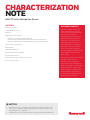
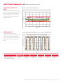
THE GAS RESPONSE CURVE
The data in Figure 1 shows a typical
response curve for the AQ3STF.
Test data was taken from current
production at the time of release of
this document, and reflects the typical
performance of a production batch at
this time.
The data in Figures 2 and 3 shows typical
response and recovery profiles based on
the data above.
Figure 1. AQ3STF Gas Response and Recovery Profile
Figure 2. AQ3STF Gas Response Profile
Figure 3. AQ3STF Gas Recovery Profile
0
100
200
300
400
500
050100 15
02
00
Concentration(ppb)
Time (s)
AQ3STF: EOL Test
Applied Concentration (ppb)
0
100
200
300
400
500
02040608
01
00
Concentration (ppb)
Time (s)
AQ3STF: Response Curve
T90: 5s
(Typical Value < 40 s)
0
100
200
300
400
500
02040608
01
00
Concentration (ppb)
Time (s)
AQ3STF: Recovery Curve

AQ3STF Sulfur Dioxide Gas Sensor Characterization Note | sps.honeywell.com/ast |
AQ3STF Sulfur Dioxide (SO2) Gas Characterization Note
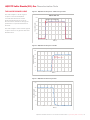
LINEARITY
The data in Figure 4 shows the typical
linearity performance of the AQ3STF gas
sensor when subjected to differing Sulfur
Dioxide concentrations which is
0 ppb to 1000 ppb.
The presented results reflect the
performance of a typical production
batch. Across typical measurement
ranges for atmospheric monitoring, the
sensor can often be considered linear.
Figure 4. Output Linearity from 0 ppb to 1000 ppb
0
100
200
300
400
500
600
700
800
900
1000
0100 200300 400500 600700 800900 1000
Measured Concentration (ppb)
Applied Concentration (ppb)
AQ3STF: Linearity
Applied Concentration (ppb) 0 20 40 80 100 200 400 500 800 1000
Measured concentration (ppb) 0 18 39 79 99 201 400 499 799 1000
TEMPERATURE
CHARACTERISTICS
Variation of Sensitivity with
Temperature
The sensitivity of the AQ3STF Series gas
sensor will vary as a function of ambient
temperature. The data in Figure 5 shows
the typical output performance across
the operating temperature range and is
presented normalized to the 20°C value
with clean air.
For instruments that are expected to
function across a wide range of ambient
temperatures. Honeywell recommends
that an electronic compensation
algorithm is used to ensure maximum
accuracy. The presented results reflect
the performance.
Figure 5. Sensitivity vs. Temperature without Compensation
Temperature (°C) 20 10 0 10 20 30 40 50
+3SD (equivalent to 99.7% confidence) 90 94 97 100 100 107 108 113
+2SD (equivalent to 95% confidence) 88 92 96 99 100 106 106 109
Mean (%) 82 88 93 96 100 102 102 101
2SD (equivalent to 95% confidence) 76 84 90 94 100 99 99 92
3SD (equivalent to 99.7% confidence) 74 83 88 93 100 97 97 88
40
60
80
100
120
140
-20 -10 01020304050
Sensitivity normalized at 20°C (%)
Temperature (°C)
AQ3STF: Sensitivity vs Temperature
+3SD
+2SD
Mean
-2SD
-3SD

AQ3STF Sulfur Dioxide Gas Sensor Characterization Note | sps.honeywell.com/ast |
AQ3STF Sulfur Dioxide (SO2) Gas Characterization Note
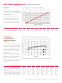
Variation of SO2 reading with
Temperature after Compensation
To ensure maximum accuracy, an
electronic compensation algorithm is
being used for above result.
The Data in Figure 6 shows the AQ3STF
reading performance across the
operating temperature range after
compensation.
Figure 6. SO2 Reading vs Temperature after Compensation
-38%
-28%
-18%
-8%
3%
13%
23%
33%
250
300
350
400
450
500
550
-20 -10 01020304050
SO2 Reading Variation
SO2 Reading After Compensation (ppb)
Temperature (°C)
AQ3STF: Reading Aer Compensaon
+3SD
+2SD
Mean (ppb)
-2SD
-3SD
Temperature (°C) 20 10 0 10 20 30 40 50
+3SD (equivalent to 99.7% confidence) 449 427 424 418 411 425 434 450
+2SD (equivalent to 95% confidence) 429 417 415 410 407 417 424 433
Mean (%) 387 397 398 393 399 401 403 399
2SD (equivalent to 95% confidence) 346 376 382 377 391 385 382 365
3SD (equivalent to 99.7% confidence) 325 366 373 368 387 377 372 348
Baseline Offset with Temperature
after Compensation
The electrical output in the absence of
target gas
(baseline offset) of the AQ3STF will
vary as a function of the ambient
temperature . The data on the right shows
typical AQ3STF performance across
the operating temperature range, for
sensors calibrated at 20°C with clean air.
Although the variation is relatively small,
Honeywell recommends the use of offset
correction factors so as to minimize
inaccuracies in the span measurement.
The presented results are being
compensated with correction factors.
You may find the correction factors in the
note on page 9. The presented results
reflect the typical performance of a
production batch.
Figure 7. Baseline vs Temperature after Compensation
-80
-60
-40
-20
0
20
40
60
80
-30 -20 -10 0102030405
06
0
Reading after compensation(ppb)
Temperature (°C)
AQ3STF: Baseline Reading@T

AQ3STF Sulfur Dioxide Gas Sensor Characterization Note | sps.honeywell.com/ast |
AQ3STF Sulfur Dioxide (SO2) Gas Characterization Note
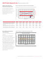
LONGTERM SENSITIVITY
DRIFT
The typical long term sensitivity of the
AQ3STF is represented in Figure 8, which
reflects the performance of a typical
production batch The sensor batches
under test were stored and tested in
ambient conditions.
Figure 8. LongTerm Sensitivity Drift
REPEATABILITY
The data in Figure 9 show the
repeatability performance of the AQ3STF
sensor when exposed repeatedly to
SO2. The presented results reflect the
performance of a typical production
batch.
Figure 9. Repeatability of AQ3STF Sensor response to 400 ppb SO2
-30%
-20%
-10%
0%
10%
20%
30%
0306090120 150 180 210
Sensitivity drift (%)
Time (day)
AQ3STF: Long-term Stability Performance
-50
0
50
100
150
200
250
300
350
400
450
0 100 200 300 400 500 600700 800 900 1000 1100
Response (ppb SO2)
Time (s)
AQ3STF: Repeatability when Exposed to 400 ppb SO2
1st
application
2nd 3rd 4th 5th 6th
Mean response (ppb) 412 408 406 405 404 402
Standard deviation (ppb) 4 3 5 6 5 4

AQ3STF Sulfur Dioxide Gas Sensor Characterization Note | sps.honeywell.com/ast |
AQ3STF Sulfur Dioxide (SO2) Gas Characterization Note
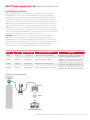
CALIBRATION GUIDELINES
Honeywell AQ3 Series gas sensors provide very stable signals over time and for
many applications, instruments containing AQ3 gas sensors only require periodic
recalibration. The time interval required between initial calibration and subsequent
recalibrations is dependent on various factors. In strenuous applications involving
extremes of operation, or for sensors used in safety applications, frequent instrument
calibration may be required. Electrochemical gas sensors need a certain amount of
oxygen to function. Generally, a few thousand ppm oxygen is sufficient. However, as
calibration normally involves exposing the sensing face of the AQ3 gas sensor to gas
for a relative short period of time, a calibration gas need not contain oxygen-sufficient
oxygen is supplied from the ambient air, for a limited time. In most cases, a five minute
exposure time is sufficient to achieve a stable calibration signal.
Safety Note: Many AQ3 gas sensors are designed to be used in safety critical
applications. To ensure that the sensor and/or instrument in which it is used, is
operating properly, it is a requirement that the function of the device is confirmed by
exposure to target gas (bump check) before each use of the sensor and/or instrument.
Failure to carry out such tests may jeopardize the safety of people and property.
Please be aware the recommended flow rate below is for a batch (6 sensor).
Sensor Warm-up
time
Calibration Gas
Concentration Gas Path Saturation EOL Step
AQ3CO 24 hours 1 ppm CO 1 ppm 2 L/min for 10 minutes Ambient Air 1 min à Clean Air 3 mins à
1 ppm CO 3 mins à Clean Air 2 mins
AQ3STF 24 hours 400 ppb SO25 ppm 2 L/min for 5 minutes Ambient Air 2 mins à Clean Air 3 mins à
400 ppb SO2 2 mins à Clean Air 3 mins
AQ3OZ 24 hours 400 ppb O32 ppm 2 L/min for 40 minutes Ambient Air 1 min à Clean Air 40 mins à
400 ppb O3 5 mins à Clean Air 3 mins
AQ3ND 24 hours 400 ppb NO25 ppm 100 mL/min for 30 minutes Ambient Air 1 min à Clean Air 40 mins à
400 ppb NO2 5 mins à Clean Air 5 mins
Figure 10. Calibration Schematic

AQ3STF Sulfur Dioxide Gas Sensor Characterization Note | sps.honeywell.com/ast |
AQ3STF Sulfur Dioxide (SO2) Gas Characterization Note
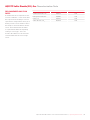
RECOMMENDED GAS FLOW
RATES
A suitable flow rate is required to ensure
accurate calibration – it also means that
the response from an AQ3 gas sensor is
equivalent in configurations where gas is
flowing over the sensor and those where
the sample is allowed to diffuse into the
sensor. The minimum flow rate which
is required will be different depending
on the gas sensor type – these are
shown in the table Please be aware the
recommended flow rate is for a single
sensor.
Gas Sensor Type Flow Rate (ml/min)
Carbon Monoxide, CO AQ3CO 500
Nitrogen Dioxide, NO2AQ3ND 500
Ozone, O3AQ3OZ 500
Sulfur Dioxide, SO2AQ3STF 500

AQ3STF Sulfur Dioxide Gas Sensor Characterization Note | sps.honeywell.com/ast |
AQ3STF Sulfur Dioxide (SO2) Gas Characterization Note
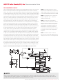
RECOMMENDED CIRCUIT
The recommended circuit for un-biased 4-electrode AQ3 Series gas sensor is shown
below. The description below can be applied to all AQ3 Sensors (unless otherwise
noted). The circuit is essentially divided into two parts. The first part is a potentiostat
circuit designed to keep the sensor sensing -reference voltage constant. An op amp is
used to compare voltage at the reference pin to a stable bias voltage. Any movement
of the reference pin voltage is compensated for by adjusting voltage on the counter
pin. The circuit should draw no current from the sensor reference pin or the sensor
output will be unstable. Further, the offset voltage of this op amp needs to be very
low (typically 60 uV to 100 uV) or be nulled out, as offset in the circuit will appear
as baseline offset in the sensor / instrument. The second part of the circuit, applied
to both sensing and auxiliary pins, is a trans-impedance amplifier (TIA). The job of
this circuit is to amplify the small current generated at the sensing pin when gas is
detected and convert to a much larger voltage output which can be easily measured
by instrumentation. Input is via a small load resistor (R106, R121 in the example
circuit), whose value is specified on the sensor datasheet. Gain of this circuit is
controlled by the feedback resistor, which is typically 20k to 1M (R107, R122 in the
example). The circuit gain should be high enough to give a readable output, but not
so high as to saturate the op amp at its highest (overload) output. The circuit below
is based on operation from a single rail 5 V op-amp circuit with rail to rail output and
a virtual ground reference for the sensor of 2.5 V. The output from the circuit will be
positive with respect to virtual ground for sensors measuring oxidizing gases (CO and
SO2) while the op amp output voltage ranges from 2.5 V to 4.5 V (2 V margin). Output
will be negative with respect to virtual ground for sensors measuring reducing gases
(NO2 and O3) while the op amp voltage ranges from 2.5 V to 0 V (2.5 V margin). Please
be aware that signals for NO2 and O3 sensors are negative when using below circuit,
remember to reverse the output signal when you use this circuit in real applications.
U100 – This LDO (LP5907 or similar,
with low noise and low IQ) is to provide a
stable voltage for the circuit. Please refer
to chosen LDO datasheet for more detail.
U104 – This amplifier act as a trans-im-
pedance amplifier (TIA) - current to
voltage converter only.
U102 – This dual op amp amplifier
should have either a low offset (<100 uV
typical) or have its offset nulled out. This
amplifier should also have a low power
consumption. A suitable op amp is the
OPA2336E or similar. This amplifier is
used both as potentiostat and a current
to voltage converter (trans-impedance
amplifier).
U101 – The Zener diode circuit is to
provide an accurate and stable reference
voltage (2.5 V) to serve as virtual ground.
, NOTE
Other op amp configurations may be used, including single- and dual-supply rails. In this case the reference voltage (bias
voltage) will need to change to suit the circuit output range and sensor output, avoiding saturation of the op amp at limits of
operation and ensuring a stable bias/virtual ground reference voltage.
Figure 11. Recommended Circuitry for 4-electrode AQ3 Series Gas Sensors

AQ3STF Sulfur Dioxide Gas Sensor Characterization Note | sps.honeywell.com/ast |
AQ3STF Sulfur Dioxide (SO2) Gas Characterization Note
COMPENSATION LOGICS OF AQ3 SERIES SENSORS
This compensation logics provides customers with insights into our air-quality AQ3
Series sensors.
AQ3 Series sensors, including AQ3CO, AQ3STF, AQ3ND and AQ3OZ, are specially
designed for high-precision and high-accuracy detection of ppb-level CO, SO2,
NO2 and O3 in ambient environment. As electrochemical sensors, AQ3 Series are
sensitive to the temperature variation, resulting in zero-background current change
and sensitivity change that are well-known for long years. Compensation for these
changes is indispensable for real-time and high-accuracy monitoring of ppb-level air
pollutants. Therefore, in this Characterization Note we are mainly focusing on well-
simulated algorithms to make up for these changes, thus enhancing the accuracy and
precision of result in the field application.
There are four electrodes in AQ3 Series sensors, i.e. sensing electrode, auxiliary
electrode, reference electrode and counter electrode. For customers, the signals of
sensing electrode and auxiliary electrode are most useful to compensate for zero-
background current and sensitivity in practical application. Based on our experiment
results, we provide the best-fit compensation algorithms for different kinds of AQ3
Series sensors. Some key parameters are explained as below:
WE real-time signal of sensing electrode, nA
WET
signal of sensing electrode at specific temperature in highly pure and
dry air, nA
WE20 signal of sensing electrode at 20°C in highly pure and dry air, nA
AE real-time signal of auxiliary electrode, nA
AE20 signal of auxiliary electrode at 20°C in highly pure and dry air, nA
STsensitivity of sensing electrode at specific temperature, nA/ppm
S20 sensitivity of sensing electrode at 20°C, nA/ppm
CF cross-factor, different sensors have different CF, no unit
RNO2 AQ3ND concentration reading, ppb
RO3 AQ3OZ concentration reading, ppb
r1 a function of temperature, usually r1=a1*T2+b1*T+c1, T/°C
r2 a function of temperature, usually r2=a2*T2+b2*T+c2, T/°C
r3 a function of temperature, usually r3=a3*T2+b3*T+c3, T/°C
The table below lists the compensation formula for different sensors, and the table
above gives the parameters for different sensors.
Sensor
Type Compensation Formula
AQ3STF Concentration (ppb) = [(WEWE20) - r1*(AEAE20)-r2
CF1*RNO2*r3*S20CF2*RO3*r3*S20] /(r3*S20) *1000
AQ3OZ Concentration (ppb) = [(WEWE20-r2CF1*RNO2*r3*S20)/(r3*S20)]*1000
AQ3CO Concentration (ppb) = (WEWE20– r2)/(r3*S20)*1000
AQ3ND
Note:
r1 and r2 compensates for the
zero-background current change
due to temperature variation
r3 compensates for the sensitivity
change due to temperature variation;
r1, r2 and r3 are usually function
of temperature /°C

AQ3STF Sulfur Dioxide Gas Sensor Characterization Note | sps.honeywell.com/ast |
AQ3STF Sulfur Dioxide (SO2) Gas Characterization Note
CROSS SENSITIVITY TABLE
Whilst AQ3 Series gas sensors are designed to be highly specific to the gas they are
intended to measure, they will still respond to some degree to various other gases. The
table below is not exclusive and other gases not included in the table may still cause a
sensor to react.
IMPORTANT NOTE: The cross sensitivity data shown below does not form part
of the product specification and is supplied for guidance only. Values quoted
are based on tests conducted on a small number of sensors and any batch may
show significant variation. For the most accurate measurements, an instrument
should be calibrated using the gas under investigation.
Gas Gas Concentration Cross Interference
Carbon Monoxide, CO 5 ppm ~None
Nitric Oxide, NO 5 ppm ~None
Nitrogen Dioxide, NO20.4 ppm 110%<x%<0%
Hydrogen Sulfide, H2S 5 ppm ~None
Ozone, O3 0.4 ppm 50%<x%<0%
Isobutylene, C4H85 ppm ~None

FOR MORE INFORMATION
Honeywell Advanced Sensing
Technologies services its customers
through a worldwide network of sales
offices and distributors. For application
assistance, current specifications, pricing
or the nearest Authorized Distributor,
visit our website or call:
USA/Canada +1 302 613 4491
Latin America +1 305 805 8188
Europe +44 1344 238258
Japan +81 (0) 367307152
Singapore +65 6355 2828
Greater China +86 4006396841
Honeywell
Advanced Sensing Technologies
830 East Arapaho Road
Richardson, TX 75081
sps.honeywell.com/ast AQ3STF Characterization Note ECN 5062 | 0027281EN | 1 | 05/21
© 2021 Honeywell International Inc. All rights reserved.
WARRANTY/REMEDY
Honeywell warrants goods of its manufacture
as being free of defective materials and
faulty workmanship during the applicable
warranty period. Honeywell’s standard product
warranty applies unless agreed to otherwise by
Honeywell in writing; please refer to your order
acknowledgment or consult your local sales
office for specific warranty details. If warranted
goods are returned to Honeywell during the
period of coverage, Honeywell will repair or
replace, at its option, without charge those
items that Honeywell, in its sole discretion,
finds defective. The foregoing is buyer’s sole
remedy and is in lieu of all other warranties,
expressed or implied, including those of
merchantability and fitness for a particular
purpose. In no event shall Honeywell be
liable for consequential, special, or indirect
damages.
While Honeywell may provide application
assistance personally, through our literature
and the Honeywell web site, it is buyer’s sole
responsibility to determine the suitability of
the product in the application.
Specifications may change without notice.
The information we supply is believed to
be accurate and reliable as of this writing.
However, Honeywell assumes no responsibility
for its use.
m WARNING
MISUSE OF
DOCUMENTATION
• The information presented in
this characterization note is for
reference only. Do not use this
document as a product installation
guide.
• Complete installation, operation,
and maintenance information
is provided in the instructions
supplied with each product.
Failure to comply with these
instructions could result in death or
serious injury.
-
 1
1
-
 2
2
-
 3
3
-
 4
4
-
 5
5
-
 6
6
-
 7
7
-
 8
8
-
 9
9
-
 10
10
-
 11
11


Honeywell AQ3STF Sulfur Dioxide Gas so2 Sensor Mode d'emploi
- Taper
- Mode d'emploi
dans d''autres langues
Autres documents
-
Comelit 47RT282EC-H Manuel utilisateur
-
 Tecno Control TS282EHCL Manuel utilisateur
-
Altair 5X Multigas Detector Le manuel du propriétaire
-
SICK Additional information for analyzers, measuring devices and traffic sensors according to EN IEC 61010-1:2011 Mode d'emploi
-
Mettler Toledo O2 Sensor InPro6950 Gas Mode d'emploi
-
-
-
-
-
