Chalmit lighting NexLED Guide d'installation
- Taper
- Guide d'installation

I-NELE-01.doc Issue 17 01/01/2021 1
IOM – NexLED - ZONE 1 BULKHEAD (ATEX & IECEx)
INSTALLATION
,
OPERATION AND MAINTENANCE INSTRUCTIONS
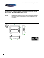
NexLED - Bulkhead Luminaires
ATEX & IECEx
Important: Please read these instructions carefully before installing or maintaining this equipment.
Good electrical practices should be followed at all times and this data should be used
as a guide only.
168
99
300
205
2 x M20
Entries

I-NELE-01.doc Issue 17 01/01/2021 2
IOM – NexLED - ZONE 1 BULKHEAD (ATEX & IECEx)
Type Of Protection Ex e mb (Increased safety,encapsulation), Ex tb (dust)
Protection Standards (IEC) EN 60079-0, (IEC) EN 60079-7, (IEC) EN 60079-18, (IEC) EN 61241-1
Area Classification Zone 1 and Zone 2 areas to (IEC) EN 60079-10-1
Zone 21 and Zone 22 areas to (IEC) EN 60079-10-2
Installation (IEC) EN 60079-14
Certificate IECEx Certificate of Conformity IECEx BAS09.0062
EC - Type Examination Certificate Baseefa04ATEX0245
Equipment Coding Ex e mb IIC T4 Gb -45°C Ta +55°C
Ex tb lllC T95°C Db IP6X
ATEX Coding II 2GD
Ingress Protection IP66/67 to EN/IEC 60529
Laser safet
y
class Class 1 LED product
CE Mark
The CE marking of this product applies to "The Electrical Equipment (Safety) Regulations
2006", "The Electromagnetic Compatibility Regulations 2004", the “Waste Electrical and
Electronic Equipment Regulations 2006” and the "Equipment and Protective Systems intended
for use in Explosive Atmospheres Regulations 1996". [This legislation is the equivalent in UK
law of EU directives 2014/35/EU, 2014/30/EU, 2012/19/EU and 2014/34/EU respectively].
The Equipment is declared to meet the provisions of the ATEX directive (2014/34/EU)
by reason of the EC Type Examination and compliance with the Essential Health and
Safety Requirements.
M Poutney Technical Manager
1.0 Introduction
The Chalmit NexLED brings to hazardous areas the very latest in lighting technology. It is a compact light source
that uses ultra bright light emitting diodes to provide light from mains power. The LEDs are maintenance free and
can last up to 80000 hours or more. They are housed in an impact and corrosion resistant marine grade
aluminium enclosure with a toughened glass lens. The control gear is electronic with regulated lamp output. The
LEDs work equally well at very low temperatures as they do at high and produce a product with very low overall
power consumption. The LEDs also emit no ultra-violet light and no forward heat.
The product is available with 2 or 6 LED’s and an accessory kit is available for exit signs.
Led 2 x 1
W
6 x 1
W
(801)
Voltage range AC 110 - 254V
Frequency range Hz 50/60/0Hz
Power Watts 220-254V 5W 10W
Current Amps 220-254V 0.05
–
0.05A 0.07
–
0.06A
Power Watts 110-130V 6W 8.7W
Current Amps 110-130V 0.05A 0.08A
The safety limit for surface temperature (T rating) is +/-10% on the rated voltage. Equipment should not be
operated continuously at more than +10/-10% of the rated voltage of the control gear.
Power Factor 0.8 minimum
Over voltage 400V ac for 1 min
Looping The looping current rating is 16A. 4mm² terminals are standard.
SPECIAL CONDITIONS FOR SAFE USE
None

I-NELE-01.doc Issue 17 01/01/2021 3
IOM – NexLED - ZONE 1 BULKHEAD (ATEX & IECEx)
Tamb Storage -40°C to +50°C
Storage Luminaires are to be stored in cool dry conditions preventing ingress of moisture
and condensation.
LED The LED used in the Nexled is the latest technology and is a class 1 LED
product.
Fuse and MCB Ratings Current consumption of an 6 x 1W (801) LED unit is 58mA and for a 2 x 1W
(201) LED unit is 49mA. It is recommended that for selection of MCB's users
should consult the MCB manufacturer. MCB ratings can vary depending on the
manufacturer and type and the size of the installation, i.e. impedance of
conductors, however type ‘C’ breakers are usually suitable. The electronic
control gear has an inrush current of 12A for less than 1ms on 230V. These
figures are worst case with low resistance connections with short cables and
low impedance supplies.
2.0 Storage
Luminaires and control gear boxes are to be stored in cool dry conditions preventing ingress of moisture and
condensation. Any specific instructions concerning emergency luminaires must be complied with.
LIVE
NEUTRAL
EARTH
ELECTRONIC
CONTROLLER
WIRING DIAGRAM FOR NON-EMERGENCY LED DRIVER
3.0 Installation and Safety
3.1 General
There are no health hazards associated with this product whilst in normal use. However, care should be
exercised during the following operations. Installation should be carried out in accordance with EN/IEC 60079-14
or the local hazardous area code of practice, whichever is appropriate, and fitting of specified insulating material
to be adhered to where a specific fire resistance rating is required. In the UK the requirements of the 'Health and
Safety at Work Act' must be met.
Handling and electrical work associated with this product to be in accordance with the 'Manual Handling
Operations Regulations' and 'Electricity at Work Regulations, 1989'. Your attention is drawn to the paragraphs
(i) 'Electrical Supplies', (ii) 'Electrical Fault Finding and Replacement' and (iii) 'Inspection and Maintenance'.
The luminaires are class 1 and should be effectively earthed. Certification details on the rating plate must be
verified against the application requirements before installation.
The information in this leaflet is correct at the time of publication. The company reserves the right to make
specification changes as required.
3.1.1 Use in Combustible Dust Atmospheres
Where the equipment is used in ignitable dust atmospheres reference must be made to the selection and
installation standards in order that the equipment is used correctly. In particular this applies to the de-rating of
surface temperature for use where dust clouds may be present. Dust layers should not be allowed to accumulate
on the surface and good housekeeping is required for safe operation. Dust in layers has the potential to form
ignitable clouds and to burn at lower temperatures.
Refer to EN (IEC) 60079-10-2 & EN (IEC) 60079-14 for additional details of selection and installation.

I-NELE-01.doc Issue 17 01/01/2021 4
IOM – NexLED - ZONE 1 BULKHEAD (ATEX & IECEx)
3.1.2 Hybrid Mixtures – Gas and Dust
Where hybrid mixtures exist as defined in EN 1127 as a potentially explosive atmosphere, consideration should
be given to verifying that the maximum surface temperature of the luminaire is below the ignition temperature of
the hybrid mixture.
3.2 Tools
No 1/2 Philips/Pozidriv/T20 Torx screwdrivers
3mm and 5mm flat blade screwdriver
Spanners for installing cable glands. Pliers, knife, wire strippers/cutters.
3.3 Electrical Supplies
The standard unit is rated for a nominal 110V-254V AC 50Hz or 60Hz. A maximum voltage variation of +6%/-6%
on the nominal is expected. (The safety limit for T rating is +10%). Equipment must not be operated outside of
the rated voltage of the control gear. The lamp supply is regulated therefore the light output over the supply
range is constant.
3.4 LED Array & Driver
This product is fitted with LED lamps that can last in excess of 80000 hours. Therefore in many applications
replacement of the LED array will be unnecessary. If replacement is required ensure mains supplies are isolated
before commencing work. Remove the front cover and then remove the LED array mounting plate by
disconnecting the cables. In the event that the LED Driver needs replacement first disconnect the cables then
remove the Torx head screws. Assembly is the reverse of disassembly making sure that the polarity is correct
that the earths are connected and also ensuring the gasket/glass mating surfaces are clean and cables are not
trapped.
3.5 Mounting
Luminaires should be installed where access for maintenance is practical and in accordance with any lighting
design information provided for the installation. Mounting is by 4 holes in the base of the body casting external to
the gasket. These should be secured with lock washers or self-locking nuts and bolts and are accessed by
removing the front cover. Any mounting attitude may be used.
3.6 Cabling and Cable Glands
3.6.1 Cables
The maximum conductor size is 6mm². Internal earth point is provided next to the main terminal block. 300/500V
cable ratings are adequate and no special internal construction is necessary. The standard looping cable size is
up to 6mm². The selection of cable size must be suitable for the fuse rating. Terminals are supplied with
suitability for looping. Where looping is used the maximum current is 16A. Terminals are accessed by removing
the front cover and LED array. Maximum cable temperature rise is 20oC above ambient.
3.6.2 Cable Glands
The installer and user must take responsibility for the selection of cables, cable glands and seals. Three tapped
cable entries are provided, two with a plug and seal suitable for permanent use, the other with a travelling plug
not suitable for use in service. Sealing plugs are similarly rated and a tool must be used for their removal. Cable
entries are M20x1.5. Cable glands and sealing plugs must have ATEX approval or be certified to EN60079-0.
For installation outside the EU suitable cable glands in accordance with IEC 60079-0 will meet the technical
requirements.
The cable and gland assembly when installed must maintain a minimum of IP54 rating.
The cable glands must be suitable for the application. Where brass cable glands are used in a corrosive
environment, cadmium or nickel plating should be used.
4.0 Inspection and maintenance
Visual inspection should be carried out at a minimum of 12 monthly intervals and more frequently if conditions
are severe; refer to EN/IEC 60079-17.

I-NELE-01.doc Issue 17 01/01/2021 5
IOM – NexLED - ZONE 1 BULKHEAD (ATEX & IECEx)
4.1 Electrical fault finding and replacement
Any fault finding must be done by a competent electrician with the luminaire isolated and, if carried out with the
luminaire in place, under a permit to work. Fault finding is by substitution with known good components.
5.0 Routine Maintenance
Visual tests and checks should be carried out at intervals described by the appropriate regulations, EN/IEC
60079-17, and should include the following:
Check that the LEDs are working.
Check for mechanical damage/corrosion.
Check for loose connections including earthing.
Check for undue accumulations of dust or dirt.
Verification of tightness of fixing, glands, blanking plugs etc.
Check for unauthorised modifications.
Check condition of enclosure gasket and fastenings.
Check for any accumulation of moisture.
Periodic inspection of the enclosure seal should be carried out to ensure that the seal is sound.
If the luminaire has been subject to abnormal conditions, for example, severe mechanical impact or chemical
spillage, it must be de-energised until it has been inspected by an authorised and competent person. If in doubt,
the unit should be returned to Chalmit for examination and, if necessary, replacement.
Before re-assembling, all connections should be checked and any damaged cable replaced.
6.0 Disposal of Material
The unit is mainly made from incombustible materials. The control gear contains plastic resin and electronic
components. All electrical components may give off noxious fumes if incinerated. Take care to render these
fumes harmless or avoid inhalation. Any local regulations concerning disposal must be complied with. Any
disposal must satisfy the requirements of the WEEE directive [2012/19/EU] and therefore must not be treated as
commercial waste.
To comply with the Waste Electrical and Electronic Equipment directive 2012/19/EU the
apparatus cannot be classified as commercial waste and as such must be disposed of or
recycled in such a manner as to reduce the environmental impact.

I-NELE-01.doc Issue 17 01/01/2021 6
IOM – NexLED - ZONE 1 BULKHEAD (ATEX & IECEx)
EU-Declaration of conformit
y
UE-Déclaration de conformité
EU-Konformitätserklärung
Manufacturer Chalmit Address 388 Hillin
g
ton Road, Glas
g
ow. G52 4BL Scotland UK
Product Nexled Luminaire.
EC - T
y
pe Examination Certificate Baseefa04ATEX0245
Notified Bod
y
SGS Fimko OY 0598
ATEX Coding II 2 GD ATEX Classification Group II Category 2 GD
Equipment Coding Ex e mb IIC T4 Gb , Ex tb lllC T95°C Db IP6X -45°C Ta +55°C
In
g
ress Protection IP66/67
The technical basis, with respect to equivalence of
La base technique, en ce qui concerne l'équivalence de
Die technische Grundla
g
e hinsichtlich der Normen
Protection Standards EN 60079-0, EN 60079-7, EN 60079-18, EN 61241-1
Area Classification EN 60079-10-1and EN 60079-10-2
of compliance with the EHSRs is valid as there are no chan
g
es which materiall
y
affect the state of technolo
g
ical pro
g
ress of the product.
en conformité avec les EESS est valide puisqu'il n'y a aucun changement qui affecte matériellement l'état de l'évolution technologique du
produit.
zur Erfüllung der GSGA ist gegeben, da keine Änderungen erfolgt sind, die einen Einfluss auf den technischen Stand des Produkts haben.
Terms of the directive: Standard & Date Certified to Standards Date Declared to
Prescription de la directive: Standard & date certifiée à Normes date Déclaré
Bestimmungen der Richtlinie: Standard & Datum
Zertifiziert nach
Standards Datum erklärt
2014/34/EU Equipment and protective systems intended for use in
potentially explosive atmospheres.
EN 60079-0: 2007 2012
EN 60079-7: 2007 2015
2014/34/UE Appareils et les systèmes de protection destinés à être
utilisés en atmosphères potentiellement explosibles.
EN 60079-18: 2004
EN61241-1:2004
2015
EN 60079-31: 2014
2014/34/EU Geräte und Schutzsysteme zur bestimmungs-
g
emäßen Verwendun
g
in explosionsfähi
g
en Bereichen.
2014/30/EU Electromagnetic compatibility EN 55015 : 2013
2014/30/UE Compatibilité électroma
g
nétique EN 61547 : 2009
2014/30/EU Elektroma
g
netische Verträ
g
lichkeit EN 61000-3-2 : 2014
2014/35/EU Low volta
g
e equipment EN 60598-1 : 2015
2014/35/UE
É
quipements électriques à bas volta
g
eEN 60598-2-5 : 2015
2014/35/EU Niederspannungsgeräte / -systeme EN 60529 : 1992
2012/19/EU Waste of electrical and electronic equipment
2012/19/UE Déchets d'équipements électriques et électroniques
2012/19/EU Entsorgung der elektrischen und elektronischen Geräte
/ S
y
steme
2011/65/EU RoHS II Directive

I-NELE-01.doc Issue 17 01/01/2021 7
IOM – NexLED - ZONE 1 BULKHEAD (ATEX & IECEx)
On behalf of the Chalmit, I declare that, on the date the equipment accompanied by this declaration is placed on the market, the equipment conforms to all
technical and re
g
ulator
y
requirements of the above listed directives.
En tant que représentant du fabricant Chalmit, je déclare qu'à la date où les équipements accompagnant cette déclaration sont mis sur le marché, ceux-ci
sont conformes à toutes les dispositions ré
g
lementaires et techniques des directives énumérées ci-dessus.
Hiermit bestätige ich, im Namen von Chalmit, dass am Tag der Lieferung des Produkts/der Produkte zusammen mit dieser Erklärung das Gerät/die Geräte
alle technischen und regulativen Anforderungen der oben aufgeführten Direktiven erfüllt.
Name and Date Mark Poutney 01/01/2021 Technical Manager
Nom et Date Directeur technique
Name und Datum Technischer Leiter
Quality Assurance Notification by: SGS Fimko OY Quality Management System Acreditation: ISO 9001
Notification d'assurance qualité par: 0598 S
y
stème de Mana
g
ement Qualité Accréditation:
Qualitätssicherun
g
snotifikation durch: Qualitätsmana
g
ements
y
stem Akkreditierun
g
:
Environmental Management System. ISO 14001
S
y
stème de
g
estion de l'environnement.
by
/par/durch
Umwelt kontroll system. Loyd's Register
Certificate No./Certificat N°/Zertifikat Nr. LRQ 4005876
-
 1
1
-
 2
2
-
 3
3
-
 4
4
-
 5
5
-
 6
6
-
 7
7


Chalmit lighting NexLED Guide d'installation
- Taper
- Guide d'installation
dans d''autres langues
Documents connexes
Autres documents
-
 Hadar Lighting HDN106 Guide d'installation
-
Dialight SafeSite LED Bulkhead Pole Mount Guide d'installation
-
Raychem NGC-20-C(L)-E Guide d'installation
-
Eaton PXLED Operating Instructions Manual
-
KILLARK L1L Series Guide d'installation
-
Eaton GHG 731 11 Mode d'emploi
-
Eaton GHG 449 2 Operating Instructions Manual
-
