Eaton PXLED Operating Instructions Manual
- Taper
- Operating Instructions Manual

Explosionsgeschützte Strahlerleuchte Typ: PXLED
Explosion protected flood light type: PXLED
Projecteur à LED pour atmosphères explosives Série: PXLED
Betriebsanleitung
Operating instructions
Mode d’emploi
C
R
OUS
E-HIND
S
S
ERIE
S
300 8000 1466 D/GB/F (-)

2
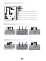
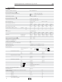
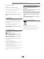
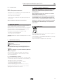
Bild 1 / fig. 1 / Fig.1 Netzanschluss / Mains connection / Raccordement au secteur
LED 1
LED 2
+
-
PE
LN
-
+
-
+
-
+
PE
LN
PE
PE
A
C
B
B
1
1
2
2
3 4 5
D
D
D
L1NPE L3 L2
L1NPE
PXLED 15L; PXLED 20L; PXLED 25L; PXLED 30L
PXLED 5L PXLED 10L
L1 N PEL3L2
L1
N PE
A Treibermodul qTEK Module qTEK Module qTEK
B Grund Modul Basic module Module de base
C
Klemmen Terminals bornes
D Stecker Plug fiche
1
rot red rouge
2
schwarz black noir
3
schwarz black noir
4
blau blue bleu
5
gn/ge gn/ye gn/ye
L1NPE L3 L2
L1 N PEL3L2

3
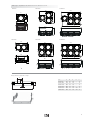
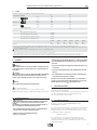
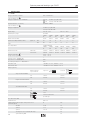
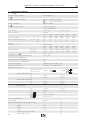
Bild 2 / fig. 2 / Fig.2 Maße in mm / Dimensions in mm / Dimensions en mm
835
798
465
858
325
197
835
798
465
858
325
197
607
465
607
325
197
303
502
259
197
502
PXLED 5l PXLED 15l PXLED 25l
PXLED 10l PXLED 20l PXLED 30l
A
B
D
C
E
mm A B C D E
PXLED 5lm 343 50 120 --- 13
PXLED 10lm 476 50 120 --- 13
PXLED 15lm 608 49 120 --- 13
PXLED 20lm 608 49 120 --- 13
PXLED 25lm 866 49 120 270 13
PXLED 30lm 866 49 120 270 13
Bügel / bracket / support de montage
255
197
343
265
343
607
465
607
325
197

4
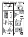
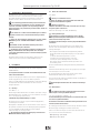
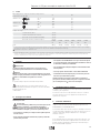
EN/IEC 60079-14
E X
M 12 /
Ø 13
5x
3x
SW 24
90°
90°
90°
90°
1 2
3
4
5 6
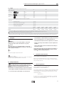
PXLED installieren PXLED installing
7 8
Installation du PXLED
D GB F
SW 8

5
1,2 Nm
9 10
4,5 Nm
11
PXLED installieren PXLED installing PXLED installer
D GB F
EN/IEC 60079-14
Test

6
Explosionsgeschützte Strahlerleuchte Typ: PXLED
D
1 Technische Daten
1.1 PX LED
EU-Baumusterprüfbescheinigung BVS 17 ATEX E 013 X
(Besondere Bedingungen siehe
X
ATEX - IEC
)
Kennzeichnung nach 2014/34/EU und Norm
II 2 G
Ex db eb op is q IIC T4 Gb
II 2 D
Ex tb op is IIIC T100 °C Db
IEC Ex Prüfbescheinigung IECEx BVS 17.0004 X
(Besondere Bedingungen siehe
X
ATEX - IEC
)
Kennzeichnung nach IEC Ex Ex db eb op is q IIC T4 Gb
Ex tb op is IIIC T100 °C Db
Bemessungsspannung AC: 110 ... 277 V DC: 127 ... 270 V
Bemessungsfrequenzbereich: 50 / 60 Hz
PXLED
5L
PXLED
10L
PXLED
15L
PXLED
20L
PXLED
25L
PXLED
30L
Bemessungsstrom (bei 230 V): 0,24 A 0,48 A 0,72 A 0,96 A 1,20 A 1,44 A
Anzahl PX LED pro MCB (T
U
40 °C) Typ B / C 10 A 38 19 12 9 7 6
16 A 60 30 20 15 12 10
Licht:
Farbtemperatur: 5700 K (Standard)
PXLED
5L
PXLED
10L
PXLED
15L
PXLED
20L
PXLED
25L
PXLED
30L
Lichtstrom: breitstrahlend 5207 lm 10414 lm 15621 lm 20828 lm 26035 lm 31242 lm
tiefstrahlend 5386 lm 10772 lm 16158 lm 21544 lm 26930 lm 32316 lm
Zulässige Umgebungstemperatur:
X
ATEX - IEC
(1)
-50 °C ... +55 °C
Lagertemperatur in der Originalverpackung -50 °C ... +55 °C
Schutzklasse nach EN/IEC 61140 I
Schutzart nach EN/IEC 60529 IP67
Photobiologische Sicherheit nach EN/IEC 62471: RG 1
LED Lebensdauer L80 >200 000 h bei +25 °C / 60 000 h bei +55 °C
Treiber Lebensdauer C10 >100 000 h bei +25 °C / 60 000 h bei +55 °C
Anschlussklemmen
Klemmvermögen 2 x je
Klemme
einadrig
mehradrig
Einreihenklemme 2410-4
min.
1,0 mm² 1,0 mm²
max.
4,0 mm² 4,0 mm²
Doppelreihenklemme 2410-6
min.
1,0 mm² 1,0 mm²
max.
6,0 mm² 4,0 mm²
Mantelklemme GHG 790
min.
1,5 mm² 1,5 mm²
max.
4,0 mm² 4,0 mm²
eindrähtig
feindrähtig mit Adernendhülse
Stiftkabelschuh
Ex-e Kabel- und Leitungseinführung (KLE)
Standardausführung
M25 x 1,5
geeignete Leitungen und Prüfdrehmomente der Druckschraube
von CCH Metall KLE
ØNm
standard
10 - 16 20
optional
7 - 12 12,5
optional
13,5 - 21 30
Einschraubgewinde:
30
optional Reduzierung M20
30

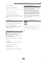
7
– Die Anforderungen der EN/IEC 60079-31, u.a. in Bezug auf übermä-
ßige Staubablagerungen und Temperatur, sind vom Anwender zu
beachten.
– Die auf der Strahlerleuchte angegebenen technischen Daten sind
zu beachten!
– Umbauten oder Veränderungen an der Strahlerleuchte sind nicht
zulässig!
– Die Strahlerleuchte ist bestimmungsgemäß in unbeschädigtem
und einwandfreiem Zustand zu betreiben!
Beachten Sie die nationalen Unfallverhütungs- und Sicherheitsvor-
schriften und die nachfolgenden Sicherheitshinweise, die in dieser
Betriebsanleitung mit einem (
) gekennzeichnet sind!
3 Normenkonformität
Die Strahlerleuchte entspricht den aufgeführten Normen, in der separat
beigelegten Konformitätserklärung.
Verweise auf Normen und Richtlinien in dieser Betriebsanleitung beziehen
sich immer auf die aktuelle Version. Zusätzliche Ergänzungen
(z.B. Jahreszahlangaben) sind zu beachten.
4 Verwendungsbereich
Die Strahlerleuchte ist zum Einsatz in explosionsgefährdeten Bereichen
der Zonen 1, 2 oder 21, 22 gemäß EN/IEC 60079-10-1 und
EN/IEC 60079-10-2 geeignet!
Die eingesetzten Gehäusematerialien einschließlich der außenliegenden
Metallteile bestehen aus hochwertigen Werkstoffen, die einen anwen-
dungsgerechten Korrosionsschutz und Chemikalienresistenz in „norma-
ler Industrieatmosphäre“ gewährleisten:
- Aluminiumlegierung
Bei einem Einsatz in extrem aggressiver Atmosphäre, können Sie
zusätzliche Informationen über die Chemikalienbeständigkeit der
eingesetzten Kunststoffe, bei Ihrer zuständigen Cooper Crouse-Hinds
Niederlassung erfragen.
2 Legende
Warnung
Dieses Symbol warnt vor einer ernsten Gefahr. Diese Warnung nicht
zu beobachten kann Tod oder die Zerstörung von Einrichtungen zur
Folge haben.
Achtung
Dieses Symbol warnt von einem möglichen Ausfall. Wird diese Warnung
nicht beobachtet kann der Gesamtausfall der Vorrichtung oder des
Systems oder des Betriebes erfolgen, an die es angeschlossen wird.
Hinweis
Dieses Symbol hebt wichtige Informationen hervor.
X
ATEX - IEC
Besondere Bedingungen
Dieses Symbol weißt auf Hinweise zum sicheren Betrieb gemäß
EG-Baumusterprüfbescheinigung / IECEx-Konformitätsbescheinigung hin.
2.1 Sicherheitshinweise
Zielgruppe:
Elektrofachkräfte und geeignet qualifizierte, unterwiesene
Personen gemäß den nationalen Rechtsvorschriften,
einschließlich der einschlägigen Normen für elektrische Geräte in
explosionsgefährdeten Bereichen (EN/IEC 60079-14).
– Diese Strahlerleuchte darf nicht in explosions gefährdeten Berei-
chen der Zone 0 und Zone 20 eingesetzt werden.
– Nicht in das Licht der Strahlerleuchte starren.
Keine Personen blenden.
D
1.1 PX LED
geeignete Leitungen und Prüfdrehmomente der Druckschraube
von CCH Kunststoff KLE
ØNm
Dichtung 1+2+3
1 2
3
min.
max.
(2)
8,0
10,0
1,5
2,0
Dichtung 1+2
1 2
min.
max.
(2)
10,0
13,0
2,3
2,6
Dichtung 1
1
min.
max.
(2)
13,5
17,5
1,3
2,3
Einschraubgewinde:
3,0
Prüfdrehmomente
Befestigungsschrauben Treiber:
1,2 Nm
Deckelschrauben Anschlussraum:
4,5 Nm
Anschlussklemmen (Reihenklemme):
1,2 Nm
Anschlussklemmen (Bolzenklemme):
2,5 Nm
PXLED
5L
PXLED
10L
PXLED
15L
PXLED
20L
PXLED
25L
PXLED
30L
Gewicht:
9,9 kg 14,4 kg 24,3 kg 27,7 kg 38,5 kg 41,1 kg
(1)
Intensive Sonneneinstrahlung in Regionen mit hohen Umgebungstemperaturen kann im Leuchten inneren zu unzulässig hohen Erwärmungen führen.
Eine Reduzierung der Lebensdauer des EVGs und der LEDs kann eine Folge hiervon sein. Zur Vermeidung sollten in diesen Regionen tagsüber die Leuchten über einen
Lichtsensor geschaltet werden.
X
ATEX - IEC
Der Strahler darf nicht unter einer Umgebungstemperatur von -40 °C eingeschaltet werden.
(2)
Die Prüfungen der Klemmbereiche und Prüfdrehmomente wurden mit Metalldornen durchgeführt.
Bei der Verwendung von Leitungen mit unterschiedlichen Fertigungstoleranzen und Materialeigenschaften kann der Klemmbereich variieren. Bitte verwenden Sie im
Zwischenbereich eine geeignete Kombination aus Dichtungen, so dass bei zukünftigen Wartungsarbeiten an der KLE die Hutmutter nachgezogen werden kann.
Explosionsgeschützte Strahlerleuchte Typ: PXLED

8
6.2 Öffnen der Strahlerleuchte
Siehe Bild 6
Warnung vor elektrischem Schock.
Vor Öffnen des Gehäuses Spannungsfreiheit sicherstellen bzw.
geeignete Schutzmaßnahmen ergreifen.
Warnung vor Explosion.
Vor Öffnen der Gehäuse sicherstellen, dass keine explosive Umge-
bungsatmosphäre vorhanden ist.
Zubehör für die Montage: siehe CCH / EATON-Katalog.
6.2.1 Leitungseinführungen
Die Leitungen und Leitungseinführungen müssen der Min-
desttemperaturbeständigkeit in Abhängigkeit des Leuchtmittels
(siehe technische Daten) entsprechen.
Zugbelastete Anschlussleitungen sind mit geeigneten Maßnahmen
zu entlasten.
Bei der Montage der Leitungseinführungen für den Netzanschluss
beachten sie die Herstellerangaben der benutzten Dichtungen und
Leitungseinführungen!
– Die Leitung durch die Ex-Kabel- und Leitungseinführung einführen.
Für Kunststoff KLEs Leitungen/Dichtungsringe wie folgt kombiniert
werden:
von Ø 8 bis 10 mm Dichtungsein sätze 1,2 und 3,
von Ø 10 bis 13 mm Dichtungsein sätze 1 und 2 und
von Ø 13,5 bis 17,5 mm Dichtungseinsatz 1 verwenden.
Auf korrekten Sitz des verbleibenden Dichtungseinsatzes in der
Verschraubung achten.
Hinweise für Metall KLEs der beiliegenden Anleitung der Metall KLE
entnehmen.
Unbenutzte Gehäuseöffnungen müssen mit geeigneten, bescheinigten
Verschlussstopfen verschlossen werden.
Die Leitungseinführungen und Verschlussstopfen müssen für die
Zündschutzart der Strahlerleuchte zugelassen sein!
Zur Sicherstellung der erforderlichen Mindestschutzart sind die KLE fest
anzuziehen (siehe Technische Daten).
Bei übermäßigem Anziehen kann die Schutzart beeinträchtigt
werden.
6.2.2 Netzanschluss
Der elektrische Anschluss des Betriebsmittels darf nur durch
Elektrofachpersonal erfolgen (EN/IEC 60079-14).
Siehe Anschlussdiagramm und Bild 8 ... 9
Zur Aufrechterhaltung der Zündschutzart ist der Leiteranschluss mit
besonderer Sorgfalt durchzuführen.
Die minimal und maximal anschließbaren Leiterquerschnitte sind zu
beachten (siehe Technische Daten).
Die ordnungsgemäß abisolierten Anschluss leitungen der Kabel sind unter
Berücksichtigung einschlägiger Vorschriften anzuschließen.
Führen Sie Isolationsmessungen nur zwischen PE und Außenleiter L1
(L, L2, L3) sowie zwischen PE und N durch!
– Messspannung: max. 1kV DC
– Messstrom: max. 10 mA
5 Verwendung / Eigenschaften
Die Strahlerleuchte ist für besondere Einsatzbedingungen wie Offshore
Plattformen, Chemische- oder Pharmazeutische Industrie geeignet.
Die modular aufgebaute Strahlerleuchte PXLED kann nicht durch den
Betreiber um weitere Module erweitert oder verkleinert werden.
Die bestimmungsgemäße Verwendung umfasst nicht Anwen-
dungen, bei welchen hochaufladende Prozesse stattfinden. Diese
wären z.B. Ionenwinde aufgrund von Hochspannungsquellen in
näherer Umgebung oder pneumatisch geförderte Stäube, welche das
Gehäuse berühren.
X
ATEX - IEC
Der Strahler ist vor elektrostatischen Aufladungen zu schützen.
Angaben aus Punkt 3 und 4 sind bei der Verwendung zu berück-
sichtigen.
Andere als die beschriebenen Anwendungen sind ohne schriftli-
che Erklärung der Fa. COOPER CROUSE-HINDS / CEAG nicht
zulässig.
Beim Betrieb sind die in der Betriebsanleitung unter Punkt 7
genannten Anweisungen zu beachten.
Die Verantwortung hinsichtlich bestimmungsgemäßer Verwen-
dung der Strahlerleuchte unter Bezugnahme der in der Anlage
vorhandenen Rahmenbedingungen (s. Technische Daten) liegt allein
beim Betreiber.
Das Produkt ist durch Patente geschützt. Weitere Hinweise hierzu
erhalten Sie bei Ihrer Cooper Crouse-Hinds/EATON Vertretung.“
6 Installation
Für das Errichten / Betreiben sind die relevanten nationalen Vorschriften
sowie die allgemein anerkannten Regeln der Technik maßgebend
(EN/IEC 60079-14).
Unsachgemäße Installation / Betrieb der Strahlerleuchte kann zum
Verlust der Garantie führen.
Transport und Lagerung der Strahlerleuchte ist nur in Originalverpackung
und der angegebenen Lage in trockenen Räumen gestattet!
Achten sie auf Beschädigungen der Glasoberfläche während der Montage
oder Reparatur! Abrieb oder Sandstrahlen kann die mechanische
Festigkeit aufheben!
6.1 Montage
Siehe Bilder 1 ... 7
Die Montage der Betriebsmittel kann ohne Öffnen der Gehäuse erfolgen.
Bei Kabeleinführung von oben bitte nur in trockenen Räumen verwenden
oder vor Feuchtigkeit geschützt errichten.
!
Bei Wandmontage Kabeleinführung von unten.
Die Strahlerleuchte nur an den vorgesehenen Befestigungspunkten,
verwindungsfrei anschrauben.
Montagefläche z.B. Wände, Decken oder Gerüstteile müssen eben sein.
Die gewählten Schrauben müssen der Befestigungsöffnung angepasst
sein (siehe Maßbild) und darf die Öffnung nicht beschädigen
(z.B. Verwendung einer Unterlegscheibe).
Bei übermäßigem Anziehen der Befestigungsschrauben kann
das Betriebsmittel beschädigt werden.
D
Explosionsgeschützte Strahlerleuchte Typ: PXLED

9
D
Explosionsgeschützte Strahlerleuchte Typ: PXLED
6.3 Schließen der Strahlerleuchte
Bild 10 ... 11
Alle Fremdkörper sind aus dem Gerät zu entfernen.
– Auf den richtigen Sitz des Gehäuseoberteils und der Dichtungen achten.
– Alle Dichtungen müssen sauber und unbeschädigt sein.
– Die Strahlerleuchte darf nicht beschädigt sein.
– Alle Gehäuse-Kombischrauben über kreuz, gleichmäßig fest anziehen
(Prüfdrehmoment siehe Technische Daten).
Bei übermäßigem Anziehen kann die Schutzart beeinträchtigt
werden.
7 Inbetriebnahme
Vor Inbetriebnahme des Betriebsmittels sind die in den einzelnen
nationalen Bestimmungen genannten Prüfungen durchzuführen.
Außerdem ist vor der Inbetriebnahme die korrekte Funktion und
Installation des Betriebsmittels in Übereinstimmung mit dieser Betriebs-
anleitung und anderer anwendbaren Bestimmungen zu überprüfen
(EN/IEC 60079-14).
Bevor die Strahlerleuchte geschlossen wird folgendes beachten:
– Alle Dichtungen müssen sauber und unbeschädigt sein.
– Die Strahlerleuchte darf nicht beschädigt sein.
Unsachgemäße Installation und Betrieb der Strahlerleuchte führt
zum Verlust der Garantie.
8 Instandhaltung / Wartung
Die erforderlichen Wartungsintervalle sind anwendungsspezifisch
und daher in Abhängigkeit von den Einsatzbedingungen vom
Betreiber festzulegen.
Warnung vor elektrischem Schock.
Vor Öffnen des Gehäuses Spannungsfreiheit sicherstellen bzw.
geeignete Schutzmaßnahmen ergreifen.
Sicherstellen, dass beim Öffnen der Geräte keine explosive
Umgebungs atmosphäre vorhanden ist.
Halten Sie die für die Instandhaltung, Wartung und Prüfung von explo-
sions geschützten Betriebsmitteln geltenden Bestimmungen z.B.
EN/IEC 60079-17 ein!
8.1 Wartung / Inspektion allgemein
Im Rahmen der Wartung / Inspektion sind vor allem die Teile, von denen
die Zündschutzart abhängt, auf Beschädigungen zu prüfen z.B.:
– Schutzschläuche über den Anschlussleitungen.
– Gehäuse und Schutzglas auf Risse!
– Dichtungen von Strahlerleuchte und Kabel und Leitungseinführungen!
– Leitungseinführungen müssen korrosionsfrei sein!
– Klemmen und Verschlussstopfen auf festen Sitz!
Sollte bei einer Wartung festgestellt werden, dass Instandsetzungsarbei-
ten erforderlich sind, ist Abschnitt 9 dieser Betriebsanleitung zu
beachten.
9 Reparatur / Instandsetzung / Änderungen
Reparaturen, die den Explosionsschutz betreffen, dürfen nur von
CCH oder einer qualifizierten Elektrofachkraft in Übereinstimmung
mit national geltenden Regeln durchgeführt werden
(EN/IEC 60079-19).
Als Ersatz und zu Reparatur dürfen nur Originalteile von COOPER
CROUSE-HINDS / EATON verwendet werden.
Bei Schäden an der druckfesten Kapselung ist nur ein Austausch des
kompletten Betriebsmittel zulässig. Im Zweifelsfalle ist das Betriebs-
mittel an COOPER Crouse-Hinds / EATON zur Reparatur zurückzugeben.
Umbauten oder Veränderungen an dem Betriebsmittel sind nicht
gestattet.
Die Strahlerleuchte ist bestimmungsgemäß in unbeschädigtem und
einwandfreiem Zustand zu betreiben.
10 Entsorgung / Wiederverwertung
Bei der Entsorgung des Betriebsmittels sind die jeweils geltenden
nationalen Abfallbeseitigungsvorschriften zu beachten.
Zusätzliche Informationen zur Entsorgung des Produktes können Sie bei
Ihrer zuständigen Cooper Crouse-Hinds Niederlassung erfragen.
Programmänderungen und -ergänzungen sind vorbehalten.

10
Explosion protected flood light type: PXLED
GB
1 Technical data
1.1 PX LED
EU type examination certificate BVS 17 ATEX E 013 X
(special conditions see
X
ATEX - IEC
)
Category of application acc to 2014/34/EU
II 2 G
Ex db eb op is q IIC T4 Gb
II 2 D
Ex tb op is IIIC T100 °C Db
IEC Ex Certification of conformity
IECEx BVS 17.0004 X
(special conditions see
X
ATEX - IEC
)
Category of application: Ex db eb op is q IIC T4 Gb
Ex tb op is IIIC T100 °C Db
Rated voltage:
AC: 110 ... 277 V DC: 127 ... 270 V
Rated frequency range: 50 / 60 Hz
PXLED
5L
PXLED
10L
PXLED
15L
PXLED
20L
PXLED
25L
PXLED
30L
Rated current (at 230 V): 0.24 A 0.48 A 0.72 A 0.96 A 1.20 A 1.44 A
Numbers PX LED per MCB (T
U
40 °C) type B / C 10 A 38 19 12 9 7 6
16 A 60 30 20 15 12 10
Light:
Color temperature: 5700 K (standard)
PXLED
5L
PXLED
10L
PXLED
15L
PXLED
20L
PXLED
25L
PXLED
30L
Rated luminous flux wide beam 5207 lm 10414 lm 15621 lm 20828 lm 26035 lm 31242 lm
narrow beam 5386 lm 10772 lm 16158 lm 21544 lm 26930 lm 32316 lm
Ambient temperature:
X
ATEX - IEC
(1)
-50 °C ... +55 °C
Storage temp. orig packing
-50 °C ... +55 °C
Insulation class to IEC/EN 61140
I
Protection acc. to IEC/EN 60529 IP67
Photobiological safety acc. to IEC/EN 62471: RG 1
LED lifetime L80 >200 000 h at +25 °C / 60 000 h at +55 °C
Driver lifetime C10 >100 000 h at +25 °C / 60 000 h at +55 °C
Calmping capacity:
Calmping capacity
2 x per terminals
single wire
multi wire
Single-row-terminal 2410-4
min. 1.0 mm² 1.0 mm²
max. 4.0 mm² 4.0 mm²
Doppel-row-terminal 2410-6
min. 1.0 mm² 1.0 mm²
max. 6.0 mm² 4.0 mm²
Terminalblock GHG 790
min. 1.5 mm² 1.5 mm²
max. 4.0 mm² 4.0 mm²
solid
multi wire with ferrules
pin cable lugs
Ex e-cable entries (KLE)
Standard version M25 x 1.5
suitable
c
ables and test torques of the pressure screw
metal cable glands
ØNm
standard 10 - 16 20
optional 7 - 12 12.5
optional 13.5 - 21
30
Test torque for screw in thread cable entry: 30
optional reducing M20
30

11
2 Principles
Warning
This symbol warns of a serious hazard. Failure to observe this
warning may result in death or the destruction of property.
Caution
This symbol warns of a possible failure. Failure to observe this
caution may result in the total failure of the device or the system or
plant to which it is connected.
Note
This symbol highlights important information.
X
ATEX - IEC
Special conditions
This symbol shows Highlights for safe use in accordance to EU-Type-Ex-
amination Certificate/ IEC Ex-Certificate of Conformity.
2.1 Safety instructions
Target group:
For skilled electricians and suitable qualified, instructed
personnel in accordance with national legislation, including
the relevant standards and, where applicable, in acc. with
IEC/EN 60079-14 on electrical apparatus for explosive atmospheres.
– The flood light is not suitable for use in hazardous areas of zone 0 and 20 .
– Do not stare into light of the flood light . Do not blind anyone.
– The requirements of the IEC/EN 60079-31 regarding excessive dust
deposits and temperature to be considered from the user.
– The technical data indicated on the flood light are to be observed!
– Changes of the design and modifications to the flood light are not
permitted!
– The flood light shall be operated as intended and in undamaged
and perfect condition!
Observe the national safety rules and regulations for prevention of
accidents and the following safety instructions which are marked
with an ( ) in these operating instructions!
3 Conformity with standards
The flood light are conform to the standards specified in the EU-Declara-
tion of conformity, enclosed separately.
References to standards and directives in these operating instructions
always relate to the latest version. Other additions (e.g. details relating to
the year) shall be observed.
4 Field of application
The flood light is intended for use in potentially explosive atmospheres in
zones 1, 2 and zones 21, 22 in accordance with
IEC/EN 60079-10-1 and IEC/EN 60079-10-2.
The enclosure materials used, including any external metal parts, are high
quality materials which ensure a corrosion protection and resistance to
chemical substances corresponding to the requirements in a “normal
industrial atmosphere”:
- Aluminium alloy
In case of use in an extremely aggressive atmosphere, you can obtain
information concerning the chemical resistance of the materials used
from your Cooper Crouse-Hinds branch.
1.1 PX LED
suitable
c
ables and test torques of the pressure screw
plastic cable glands
ØNm
Seal 1+2+3
2
3
min.
max.
(2)
8.0
10.0
1. 5
2.0
Seal 1+2
2
min.
max.
(2)
10.0
13.0
2.3
2.6
Seal 1
min.
max.
(2)
13.5
17.5
1. 3
2.3
Test torque for screw in thread cable entry (Nm): 3.0
Test torque
Mounting screws: 1,2 Nm
Cover screws connection cabinet: 4,5 Nm
Doppel-row-terminal 24110-6: 1,2 Nm
Terminalblock GHG 790: 2,5 Nm
PXLED
5L
PXLED
10L
PXLED
15L
PXLED
20L
PXLED
25L
PXLED
30L
Weight: 9.9 kg 14.4 kg 24.3 kg 27.7 kg 38,5 kg 41,1 kg
(1)
Intensive sun radiation in areas of high ambient temperatures may cause inadmissible temperature rise inside of the luminaire. This may result a decrease in lifetime of
the electronic ballast (EVG) and the LEDs. Therefore those luminaires should be switched off during daytime by a photocell control.
X
ATEX - IEC
The floodlight shall not be switched on at an ambient temperature below -40 °C.
(2)
The tests of clamping ranges and torque values were performed with metal mandrel. The clamping range can vary by using cables with different manufacturing tolerances and
material properties. Please use a suitable combination of seals in the intermediate area, so that the cap nut can be tightened in future maintenance work on the cable entry.
Explosion protected flood light type: PXLED
GB

12
5 Installation
The floodlight is suitable for special operating conditions such as on
offshore platforms or in chemical or pharmaceutical plants.
The adding of further modules or the removal of modules from the modular
PXLED floodlight by the operator is not permitted.
The intended use does not include applications with
high-charging processes. Those could be for example high-voltage
sources generating ion-winds or pneumatically transported dust
atmospheres in touch with the enclosure.
X
ATEX - IEC
The floodlight has to be protected against electrostatic
discharges.
The data as per point 3 and 4 shall be taken into account with the use.
Applications other than those described are not permitted
without Cooper Crouse-Hinds’s / EATON’s prior written consent.
The instructions stated in section 7 of the operating instructions
shall be observed during operation.
The user alone is responsible for the appropriate use of this
junction box in consideration of the basic conditions existing at the
plant (see technical data).
The product is protected by patents. For more information, please contact
your local Cooper Crouse-Hinds / EATON representative.
6 Installation
For the mounting and operation, the respective national regulations as
well as the general rules of engineering will have to be observed
(IEC/EN 60079-14).
The improper installation and operation of floodlight may result in
the explosion protection and invalidation of the guarantee.
Transport and storage only in original packaging in a closed and dry room!
Observe for any cracks or damage in housing and glass during installation
or reparation! Don´t damage the fire-finish of the glass adquired during
moulding (abrasions, sanding, etc.) that can weaken their mechanical
functions.
6.1 Montage
See fig. 1 ... 7
The flood lights can be mounted without opening their enclosure.
If cable entries are used from the top, mount only in dry rooms or attach
where protected from moisture.
!
For wall assembly Cable entry from below.
The flood light may rest evenly only at the respective fastening points.
Mounting surfaces, e.g. walls, ceilings or parts of frameworks, have to be
flat.
The chosen screw shall match the fastening hole (see dimensional
drawing) and it must not damage the hole (e. g. use of a washer).
If the screws are overtightened, the apparatus can be damaged.
6.2 Opening flood light connection cabinet
See fig 6
Warning against electric shock.
Ensure and take suitable precautions before opening the housing.
Warning of explosion.
Before opening the housing to make sure that no explosive atmos-
phere environment.
Additional mounting material see CCH / EATON catalogue.
6.2.1 Cable entries
The cables and cable entries must correspond with the minimum
temperature resistance depending on the lamp (see technical data).
Connecting cable exposed to strain must be relieved by suitable
measures.
When assembling the cable entries for the mains connection, please observe
the manufacturer’s specifications for the used seals and cable entries!
–
Introduce the cable through the Ex cable entry.
When using plastic KLEs u
se
sealing inserts 1,2 and 3 for cables from 8 to 10 mm Ø,
sealing inserts 1 and 2 for cables from 10 to 13 mm Ø
and sealing insert 1 for cables from 13.5 to 17.5 mm Ø.
Pay attention to the proper fit of the remaining sealing insert in the
cable gland.
For metal KLE see additional KLE instruction.
Unused cable entries have to be closed by a correspondante certified
blanking plug.
The cable entries and sealing stoppers must be approved for the lamp’s
type of protection!
In order to ensure the required minimum protection category, the cable
glands shall be tightened down (test torque) .
Overtightening might impair the protection category.
6.2.2 Electrical connection
The electrical connection of the equipment must be performed
by qualified electricians (IEC/EN 60079-14).
See wiring diagram and fig. 8 and 9.
All screws and/or nuts of the connection terminals, including those not in
use, shall be tightened securely.
To maintain the explosion protection, the connection of conductors
shall be carried out with special care.
The minimum and maximum conductor cross sections shall be taken
in account (see technical data).
The respective regulations shall be taken into account when connecting
the correctly stripped connection conductors of the cables.
Only carry out insulation measurements between PE and the external
conductor L1 (L, L2, L3) as well as between PE and N.
– measuring voltage: max. 1 kV DC
– measuring current: max. 10 mA
Explosion protected flood light type: PXLED
GB

13
6.3 Closing flood light
Fig 10 ... 11
Remove all foreign bodies from the device.
– Pay attention to the correct fit of the enclosure top part and the seals.
– All seals must be clean and undamaged.
– The flood light may not be damaged.
– Tighten all enclosure combi-screws evenly diagonally (test torque see
technical data).
Mind! Overtightening might impair the pull-relief effect!
7 Taking into operating
Prior to taking the apparatus into operation, the tests specified in the
relevant national regulations will have to be carried out.
Apart from that, the correct functioning and installation of the apparatus
in accordance with these operating instructions and other applicable
regulations will have to be checked (IEC/EN 60079-14).
Please observe the following before closing the flood light:
– All seals must be clean and undamaged.
– The flood light may not be damaged.
Improper installation and operation of the lamp leads to loss of the
guarantee.
8 Maintenance/Servicing
The required maintenance intervals are set according to their
application and should therefore be determined depending on the
conditions of use.
Warning against electric shock.
Before opening the enclosure make sure that the apparatus is
disconnected from the voltage, or take the appropriate protective
measures.
Make sure that there is no explosive ambient atmosphere when
opening the equipment.
The relevant national regulations which apply to the maintenance/
servicing of electrical apparatus in explosive atmospheres, shall be
observed (IEC/EN 60079-17).
8.1 General Maintenance / Inspection
Within the scope of the maintenance / inspection, especially those parts
on which the type of protection depends must be checked for damage, e.g.:
– Protective hoses over the connecting cables.
– Housing and protective glass for any cracks or damages.
– Seals for the flood light and cable glands.
– Cable entries must be free from corrosion!
– Terminals and blanking plugs must be checked for secure fitting.
If during servicing repairs prove to be necessary, section 9 of these
operating instructions will have to be observed.
9 Repairs / Overhaul / Modification
Repairs that affect the explosion protection, may only be carried
out by COOPER CROUSE-HINDS or a qualified electrician (Compe-
tent person) in compliance with the applicable national rules
(IEC/EN 60079-19).
For replacement and repair only original parts from COOPER
CROUSE HINDS-/ EATON may be used.
Should the flameproof enclosure be damaged, only a replacement
will be permitted. In case of doubt, the respective apparatus will
have to be returned to COOPER CROUSE-HINDS / EATON for repair.
Modifications to the device or changes of its design are not permitted.
They shall be used for their intended purpose and in perfect and
clean condition.
10 Disposal/Recycling
When the apparatus is disposed of, the respective national regulations on
waste disposal will have to be observed.
In case of disposal you can obtain additional information from your Cooper
Crouse-Hinds / EATON branch.
Subject to modifications or supplement of the product range.
Explosion protected flood light type: PXLED
GB

14
Projecteur à LED pour atmosphères explosives Série: PXLED
F
1 Caractéristiques techniques
1.1 PX LED
Attestation d’examen UE de type: BVS 17 ATEX E 013 X
(voir
X
ATEX - IEC
)
Marquage selon directive 2014/34/UE
II 2 G
Ex db eb op is q IIC T4 Gb
II 2 D
Ex tb op is IIIC T100 °C Db
Certificat d´essai IEC EX IECEx BVS 17.0004 X
(voir
X
ATEX - IEC
)
Marquage selon directive IEC Ex Ex db eb op is q IIC T4 Gb
Ex tb op is IIIC T100 °C Db
Tension nominale: AC: 110 ... 277 V DC: 127 ... 270 V
Gamme des fréquences: 50 / 60 Hz
PX LED
5L
PX LED
10L
PX LED
15L
PX LED
20L
PX LED
25L
PX LED
30L
Courant nom. (à 230 V): 0,24 A 0,48 A 0,72 A 0,96 A 1,20 A 1,44 A
Numéros PX LED par MCB (T
U
40 °C) Type B / C 10 A 38 19 12 9 7 6
16 A 60 30 20 15 12 10
Eclairage:
Température de couleur: 5700 K (standard)
PXLED
5L
PXLED
10L
PXLED
15L
PXLED
20L
PXLED
25L
PXLED
30L
Flux lumineux nominal: faisceau large 5207 lm 10414 lm 15621 lm 20828 lm 26035 lm 31242 lm
faisceau étroit 5386 lm 10772 lm 16158 lm 21544 lm 26930 lm 32316 lm
Température ambiante:
X
ATEX - IEC
(1)
-50 °C ... +55 °C
Température de stockage dans l’emballage original -50 °C ... +55 °C
Classe d’isolation selon CEI/EN 61140: I
Indice de protection selon CEI/EN 60529: IP67
Sécurité photobiologique selon CEI/EN 62471: RG 1
Durée de vie des LED L80 >200 000 h à +25 °C / 60 000 h à +55 °C
Durée de vie du driver C10 >100 000 h à +25 °C / 60 000 h à +55 °C
Capacité de serrage des bornes
Capacité de serrage des
bornes, 2 x par borne
unifilaire
multifilaire
Bornier à double rangée 2410-4
min. 1,0 mm²
1,0 mm²
max. 6,0 mm²
4,0 mm²
Bornier à double rangée 2410-6
min. 1,0 mm²
1,0 mm²
max. 6,0 mm²
4,0 mm²
Bornier GHG 790
min. 1,5 mm²
1,5 mm²
max. 4,0 mm²
4,0 mm²
rigide
fil souple avec embout
fil souple avec cosse
Presse étoupe polyamide Ex e
Modèle standard M25 x 1,5
Diamètre extérieur du câble et couple de serrage du chapeau Ø Nm
standard 10 - 16 20
optionnel 7 - 12 12,5
optionnel 13,5 - 21 30
Couple d' essai pour l’entrée de câble: 30
Réduction M20 optionnel 30

15
– Les exigences des CEI/EN 60079-31 en ce qui concerne des dépôts
de poussière démesurés et les températures maximales de surfaces
doivent être considérées par I’utilisateur.
– Les caractéristiques techniques indiquées sur le luminaire doivent
être respectées!
– Il n’est pas permis de transformer ou de modifier le luminaire!
– Le luminaire ne doit être exploité que pour la fonction qui lui est
dévolue et qu’en état intact et parfait!
Veuillez respecter les prescriptions nationales de sécurité et de
prévoyance contre les accidents ainsi que les consignes de sécurité
qui sont marquées d’un (
) dans ce mode d’emploi!
3 Conformité avec les normes
Les Appareils sont conformes aux normes reprises dans la déclaration de
conformité, jointe séparément.
Les références aux normes et directives dans cette notice se réfèrent
toujours à la dernière version. Les suppléments éventuels doivent
également être respectés.
4 Domaine d’utilisation
Les projecteur conviennent à l’emploi en zones 1 et zones 2 ainsi que
l’emploi en zones 21 et zones 22 d’une atmosphère explosive selon
CEI/EN 60079-10-1 et CEI/EN 60079-10-2!
Les matériaux utilisés pour le boîtier et les pièces métalliques extérieures
sont de haute qualité et garantissent une protection anticorrosion et une
résistance aux produits chimiques adaptées à une « atmosphère
industrielle normale » :
- Aluminium
En cas d‘utilisation dans une atmosphère extrêmement agressive, vous
pouvez obtenir des informations supplémentaires sur la résistance aux
produits chimiques des plastiques utilisés auprès de la filiale Cooper
Crouse Hinds / EATON compétente.
2 Légende
Avertissement
Ce symbole avertit d’un danger grave. Le non-respect de cet
avertissement peut entrainer la mort ou la destruction de biens.
Attention
Ce symbole met en garde contre un éventuel défaut. Le non-respect
de cette consigne peut entrainer une panne totale de l’appareil ou du
système ou de l’installation à laquelle il est connecté.
Remarque
Ce symbole indique la présence d’informations importantes.
X
ATEX - IEC
Conditions particulières:_Ce symbole indique la présence de
conditions particulières d’utilisation à respecter, en lien avec l’attestation
d’examen CE de type et le
certificat IEC Ex.
2.1 Consignes de sécurité
Ne pas regarder longuement la lumière du projecteur portatif. Ne pas
éblouir les personnes.
Groupe cible:
Pour les électriciens qualifiés et les personnels ayant reçu les
formations adéquates, conformément à la législation
nationale en vigueur et, si applicable, à la norme CEI/EN 60079-14
sur les installations électriques pour les atmosphères explosives.
– Ce projecteur ne convient pas a l’emploi en atmosphère explosive
de zones 0 et 20!
– Ne pas regarder longuement la lumière du projecteur portatif. Ne
pas éblouir les personnes.
Projecteur à LED pour atmosphères explosives Série: PXLED
F
1.1 PX LED
Câbles appropriés et couples d’essai de la vis de pression de
plastic Entrées de câble CCH
Ø
Nm
Garniture 1+2+3
2
3
min.
max.
(2)
8,0
10,0
1,5
2,0
Garniture 1+2
2
min.
max.
(2)
10,0
13,0
2,3
2,6
Garniture 1
min.
max.
(2)
13,5
17,5
1,3
2,3
Couple de serrage du corps: 3,0
Couples de serrage
Vis de fixation du driver: 1,2 Nm
Vis du couvercle boîte de connexion: 4,5 Nm
Bornes de connexion (fixation du rail DIN): 1,2 Nm
Bornes de connexion ( les bornes à tige ): 2,5 Nm
PXLED
5L
PXLED
10L
PXLED
15L
PXLED
20L
PXLED
25L
PXLED
30L
Poids: 9,9 kg 14,4 kg 24,3 kg 27,7 kg 38,5 kg 41,1 kg
(1)
Le rayonnement solaire intensif dans des régions à température ambiante élevée peut provoquer à l’intérieur du luminaire un échauffement extensif. Ceci peut impliquer
une réduction de durée de vie considérable. Pour pallier à cela, il est préconiser d’utiliser un interrupteur photoélectrique.
X
ATEX - IEC
Ne pas allumer le projecteur en dessous de -40°C.
(2)
Les tests des plages de serrage et les valeurs de couple de serrage ont été réalisés avec un mandrin métallique. La plage de serrage peut varier légèrement selon le type
de câble et les propriétés des matériaux utilisés. Pour les plages de serrage intermédiaires, veuillez utiliser des garnitures d’étanchéité qui laisseront la possibilité de
resserrer le chapeau du presse étoupe lors de futures opérations de maintenance.

16
5 Utilisation / propriétés
Ce projecteur est adapté pour les environnements particuliers tels que les
plateformes offshores, les sites chimiques et pharmaceutiques.
Ce projecteur modulaire ne peut pas être modifié après livraison (ajout ou
suppression de modules).
L’utilisation prévue n’inclut pas les applications avec des
processus de fortes charges électro-statiques. Ceux-ci pourraient être
par exemple des sources haute tension générant des vents ioniques
ou des déplacements pneumatiques d’atmosphères poussiéreuses
en contact avec le boitier.
X
ATEX - IEC
Le projecteur doit être protégé contre les décharges électrostatiques.
Respecter les indications des points3 et4 pendant l'utilisation.
Toute utilisation autre que celle décrite ci-dessus est interdite,
sauf accord écrit de Cooper Crouse-Hinds / EATON.
Pour l'utilisation, respecter les instructions décrites au point7 du
mode d'emploi.
Seul l’utilisateur est responsable de l’emploi comme prévu de
cette Lumière d'inondation, en tenant compte des conditions
générales existant dans l’établissement (voir Caractéristiques
techniques).
Ce produit est protégé par des brevets. Pour plus d'information, merci de
contacter votre représentant local Cooper Crouse-Hinds / Eaton.
6 Installation
Pour l’installation et l’exploitation d’appareils électriques pour atmosphère
explosive, la règlementation nationale en vigueur ainsi que les règles de la
technique généralement reconnues devront être respectées
(CEI/EN 60079-14).
L’installation inadéquates de luminaire peuvent entraîner la perte de
la garantie.
Le transport et le stockage du luminaire ne sont autorisés que dans
l’emballage d’origine et dans la position prescrite dans des locaux secs.
Veillez à ne pas endommager la surface de verre au cours du montage ou
des réparations. Le frottement ou les projections de sable peuvent porter
atteinte à ses caractéristiques mécaniques.
6.1 Montage
Voir schéma de câblage et figures 8 ... 9.
Le montage du matériel peut s'effectuer sans ouvrir les boîtiers.
Le montage des presse étoupe sur le dessus n'est possible que dans les
locaux couverts et sans projections d'eau.
!
En cas de montage mural : introduction du câble par le bas.
La fixation ne peut se faire que sur les points de fixation prévus.
Le support de fixation (mur, plafond) doit être une surface plane et
régulière.
La vis choisie doit correspondre à l'orifice de fixation (voir plan coté) sans
l'endommager (p.ex. utilisation d'une rondelle).
Le matériel peut être endommagé en cas de serrage excessif des
vis de fixation.
6.2 Ouvrir le projecteur
Voir la Fig. 6
Attention aux risques de chocs électriques. Prendre toutes les
précautions nécessaires avant d'ouvrir le boitier.
Attention aux risques d'explosions. Assurer vous qu'il n'y a pas
de présence d'une atmosphère explosive.
Accessoires pour le montage : voir le catalogue (CCH / EATON).
6.2.1 Entrées de câble
Les câbles et entrées de câble doivent correspondre à la
résistance minimale aux températures en fonction du projecteur
(caractéristiques techniques).
Les câbles de raccordement soumis à la traction doivent être
amarrés par des mesures appropriées.
Pour le montage des entrées de câble pour le raccordement au secteur,
respectez les indications du fabricant des joints et des entrées de câble
employés!
– Introduire le câble par l’entrée de câble Ex e. Utiliser des inserts d'étanchéité
1, 2 et 3 pour les câbles de 8 à 10 mm Ø,
inserts 1 et 2 d'étanchéité pour les câbles 10 -13 mm Ø
et étanchéité insert 1 pour câbles de 13,5 à 17,5 mm Ø.
Dans le cas de presse étoupe métalliques, se référer à leur notice
d'utilisation.
Les ouvertures non utilisées doivent être obturées avec les bouchons
homologués appropriés.
Les entrées de câble et les bouchons doivent être homologués pour le
type de protection antidéflagrante du projecteur!
Pour garantir le type de protection minimale nécessaire, les KLE doivent
être serrées en respectant les couples de serrage indiqués (voir Caracté-
ristiques techniques).
Un serrage excessif peut nuire au type de protection.
6.2.2 Branchement sur secteur
Le raccordement électrique du dispositif doit être éffectué
uniquement par une personne qualifiée (CEI/EN 60079-14).
Voir le schéma et l'image câblage ... 8 9
Les conducteurs seront connectés avec soin de manière à préserver
la catégorie d´explosion.
Les sections min. et max. connectables du conducteur sont à
observer (voir Caractéristiques techniques).
Raccorder les conducteurs correctement isolés des câbles en respectant
les directives applicables.
Des mesurages d’isolation ne doivent être effectués qu’entre PE et le
conducteur extérieur L1 (L, L2, L3) ainsi qu’entre PE et N!
– tension de mesurage : 1 kV CC au maxi
– courant de mesurage : 10 mA a maxi
Projecteur à LED pour atmosphères explosives Série: PXLED
F

17
Projecteur à LED pour atmosphères explosives Série: PXLED
F
6.3 Fermeture du projecteur
Fig 10 ... 11
Tout corps étranger doit être ôte du dispositif.
– Veillez au bon positionnement de la partie supérieure du boîtier et des
joints.
– Tous les joints doivent être propres et intacts.
– Le luminaire ne doit pas être endommagé.
– Serrez à fond en croisant et de façon homogène les 6 boulons à
rondelles incorporées du boîtier
(Couples de contrôle voir les Caractéristiques techniques).
Au cas où elles seraient forcées, cela pourrait être nuisible à l’indice
de protection.
7 Mise en service
Avant la mise en service du matériel, les vérifications spécifiées dans les
règlements nationaux individuels devront être exécutées. De plus, il
faudra vérifier son fonctionnement et installation corrects en conformité
avec ce mode d’emploi et avec d’autres règlements y applicables.
Avant de fermer le projecteur, respectez ce qui suit :
– Tous les joints doivent être propres et intacts.
– Le projecteur ne doit pas être endommagé.
L’installation et l’exploitation inadéquates du projecteur peuvent
entraîner la perte de la garantie.
8 Mise en service
Les intervalles d´entretien sont spécifiques aux applications et
sont donc déterminées en fonction des conditions d´utilisation.
Attention aux risques de chocs électriques. Prendre toutes les
précautions nécessaires avant d'ouvrir le boitier.
En ouvrant les appareils, veillez à ce qu’ils ne se trouvent pas
dans une atmosphère explosive.
Pour la remise en état, la maintenance et le contrôle du mode de
protection antidéflagrant, respectez les dispositions en vigueur telles que
CEI/EN 60079-17.
8.1 Entretien
Dans le cadre de la maintenance / inspection , il conviendra de vérifier
tout particulièrement les organes dont dépendent la protection ATEX,
comme par exemple :
– le bon état de la gaine extérieure du câble.
– le bon état de l'enveloppe extérieure et de la vitre!
– le bon état des différents joints!
– l'absence de corrosion!
– vérifier le serrage des presse étoupe, bouchons et bornes!
Dans le cas où des travaux de remise en état sont nécessaires, merci de
contacter au préalable votre représentant local Cooper Crouse-Hinds /
EATON (voir chapitre 9).
9 Réparation / Remise en état
Des réparations qui portent sur la protection contre l’explosion,
ne devront être exécutées que par COOPER CROUSE-HINDS /
EATON ou par un électricien qualifié en conformité avec la règlemen-
tation nationale en vigueur (CEI/EN 60079-19).
Des réparations ne doivent être exécutées qu’à l’aide de pièces
de rechange d’origine COOPER CROUSE-HINDS / EATON.
Si l’enveloppe antidéflagrante est avariée, seul un remplacement
sera admis. En cas de doute, le dispositif en question devra être
renvoyé à COOPER CROUSE-HINDS / EATON pour être réparé.
Il n’est pas permis de transformer ou de modifier ce matériel.
Ils sont prévus pour n´être utilisés qu´en parfait état de fonctionne-
ment et sans aucun dommage..
10 Évacuation des déchets /Recyclage
Lors de l’évacuation de ce matériel électrique, la règlementation nationale
respective en vigueur devra être respectée.
En cas d'élimination, vous pouvez obtenir des informations supplémen-
taires auprès de votre branche Cooper Crouse-Hinds / EATON.
Sous réserve de modification ou de supplément de cette série de
produits.

18
Notizen / Notes / Remarques

19
Notizen / Notes / Remarques

Eaton is a registered trademark.
All trademarks are property
of their respective owners.
Eaton is dedicated to ensuring that reliable, efficient
and safe power is available when it’s needed most. With
unparalleled knowledge of electrical power management
across industries, experts at Eaton deliver customized,
integrated solutions to solve our customers’ most critical
challenges.
Our focus is on delivering the right solution for the appli-
cation. But, decision makers demand more than just
innovative products. They turn to Eaton for an unwavering
commitment to personal support that makes customer
success a top priority. For more information, visit
www.eaton.com/electrical.
Changes to the products, to the information contained in this
document, and to prices are reserved; so are errors and omissions.
Only order confirmations and technical documentation by Eaton is
binding. Photos and pictures also do not warrant a specific layout or
functionality. Their use in whatever form is subject to prior approval
by Eaton. The same applies to Trademarks (especially Eaton, Moeller,
and Cutler-Hammer). The Terms and Conditions of Eaton apply, as
referenced on Eaton Internet pages and Eaton order confirmations.
C
ooper
C
rouse-Hinds
G
mbH
Neuer Weg-Nord 49
69412 Eberbach
E-Mail: [email protected]
www.crouse-hinds.de
© 2017 Eaton
All Rights Reserved
Printed in Germany
Publication No.
300 8000 1466 D/GB/F (-)
Auflage / 11.2017 / CS
CZ: "Tento návod k pouåití si m åHWH vyåiGDt
ve
svém PDWe
ském MD]yce u p íslušného
]DVWRXSHQt spole
nosti Cooper Crouse-
Hinds/CEAG ve YDãt ]HPL"
'.0RQWDJHYHMOHGQLQJHQNDQRYersættes til
DQGUH(UVSURJoJUHNYLUHUHVKRV'eres
Cooper Crouse-Hinds/CEAG leverDndør"
E: "EQFDVo necesDrio podrá soliciWDUGHVX
representDnte Cooper Crouse-Hinds/CEAG
HVWDV instrucciones de servicio en otro idiomD
GHOD8QLRQ(XURSeD
EST: "SedDNDVXWXVjuhendit omD riiJikeeles
võite NVLGD RPD ULLJLV DsXYDVW DVMDRPDVHVt
Cooper Crouse+LQGVL&($*HVLQGXVHVW
FIN: "TDUYLWWDHVVDWlPlQNlytW|RKMHHQNllQnös
RQVDDWDYLVVDWRLVHOOD(8QNLHOHOOl7HLGlQ
Cooper
Crouse-Hinds/CEAG HGXVWDMDOWDQQH
GR:
Cooper Crouse-
Hinds/CEAG"
+$NH]HOpVL~WPXWDWyWD]DGRWWRUV]iJ
nyHOYpQD&Roper Crouse-HinGV&($*FpJ
helyi képviseletén LJpQyelheti PHJ"
,6HGHVLGHUDWHODtrDGX]LRQHGHOPDQXDOH
RSHUDWLYRLQXQDOWUDOLQJXDdHOOD&RPXQLWj
(XURSHDSRtHWHULFKLHGHUODDOYRVWUR
UDSSUHVHQtDQWH&ooper Crouse-Hinds/CEAG"
LT: Šios QDXGRMLPR instrukcijos, išverstos
J su
JLPt
j NDOb , JDOLWH SDUHLNDODXWL DWVDNLQJRMe
"Cooper Crouse-Hinds/CEA*DWVWRvyb
je VDYo
ãDOyje
/9âRHNVSOXDW
FLMDV instrukciju vDlsts vDlod
YDUDWSLHSUDV t j su YDOVWV DWELOd JDM Cooper
Crouse-Hinds/CEAG p
rst vniec b
M: JistJ
ujitolbu dDn il-mDQwDO fil-linJwD
QD]]MRQDOL WDJ
KRPPLQJ DQGLUUDppre entDQW
WD&RRper Crouse Hinds/CEA*ISDMML
KRP
NL: "Indien QRRG]DNHOLMN NDQ de YHUWDOLQJ YDn
GH]HJHEUXLNVLQVWUXFWLHLQHHQDQGHUH(UWDDO
worden oSJHYUDDJd bij Uw Cooper Crouse-
+LQGV&($*YHUWHJHnZRRUGLJLQJ
36HIRUQHFHVViULDDtrDGXomRGHVWDV
LQVWUXo}HVGHRSHUDomRSDUDRXtURLGLRPDGD
8QLmR(XURSHLDSoGHVROLFLWDODMXQWRGRVHX
representDnte Cooper Crouse-Hinds/CEAG"
PL: Niniejs]
instrukcj obsXJLw odpowiedniej
wersji j
]ykowej mo nD]Dmywi
w
pU]edstDwicielstwie firmy Cooper-Crouse-
Hinds/CEAG QD dDQy NUDM
6(Q|YHUVlWWQLQJDYGHQQDmRQWDJHRch
skötselinstruktion till DQQDW EU - språk NDQ vid
EHKRYEHVWlOODVIUnQ(U&RRper Crouse-
Hinds/CEAG- representDQW
SK: "Tento niYRGQDREVOXKX9iPYR9DãRP
URGQRPMD]yku poskytQH]DVW~SHQLHVSROR
nosti
Cooper Crouse-Hinds/CEAG vo 9DãHM NUDMLQH
SLO: "NDYRGLOD ]D XSRUDER v 9DãHP MH]LNu
ODKNR ]DKWHYDWH pri pristojnem ]DVWRSQLãWYu
SRGMHWMD&RRSHUCrouse+LQGV&($*Y9DãL
GUåDYL"
RUS:
"
При необходимости, вы можете запрашивать
перевод данного руководства на другом языке
ЕС или на русском от вашего
Cooper Crouse-Хиндс / CEAG - представителей."
-
 1
1
-
 2
2
-
 3
3
-
 4
4
-
 5
5
-
 6
6
-
 7
7
-
 8
8
-
 9
9
-
 10
10
-
 11
11
-
 12
12
-
 13
13
-
 14
14
-
 15
15
-
 16
16
-
 17
17
-
 18
18
-
 19
19
-
 20
20


Eaton PXLED Operating Instructions Manual
- Taper
- Operating Instructions Manual
dans d''autres langues
- English: Eaton PXLED
- Deutsch: Eaton PXLED
Documents connexes
-
Eaton Crouse-hinds series Operating Instructions Manual
-
Eaton GHG 731 11 Mode d'emploi
-
-
-
-
-
-
-
Eaton GHG 511 Mode d'emploi
-

