Sauder Palladia Hutch 412308 Mode d'emploi
- Taper
- Mode d'emploi

NOTE: THIS INSTRUCTION
BOOKLET CONTAINS IMPORTANT
SAFETY INFORMATION.
PLEASE READ AND KEEP FOR
FUTURE REFERENCE.
English pg 1-29
Français pg 30-33
Español pg 34-37
Lot # 390090 04/21/16
Purchased: __________________
Be sure to give us a ring before
making any returns. 1-800-523-3987
Hutch
Palladia Collection | Model 412308
Need help? Visit Sauder.com to view video assembly tips or chat with a live rep.
Prefer the phone? Call 1-800-523-3987.
Share your journey!
sauder.com
Knick-knack
paddywhack,
give your stu a home.

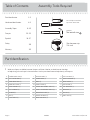
Table of Contents Assembly Tools Required
2-3
4-5
6-29
30-33
34-37
38
39
Part Identifi cation
Hardware Identifi cation
Assembly Steps
Français
Español
Safety
Warranty
Hammer
Not actual size
No. 2 Phillips Screwdriver
Tip Shown Actual Size
Skip the power trip.
This time.
412308 www.sauder.com/servicesPage 2
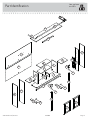
Part Identifi cation
å While not all parts are labeled, some of the parts will have a label or an inked letter on the edge
to help distinguish similar parts from each other. Use this part identifi cation to help identify similar parts.
A OUTER RIGHT END (1)
B LEFT OUTER END (1)
C INNER RIGHT END (1)
D INNER LEFT END (1)
E RIGHT UPRIGHT (1)
F LEFT UPRIGHT (1)
G DIVIDER (2)
H TOP (1)
I LONG SHELF (1)
J CENTER SHELF (1)
K LOWER BACK (1)
L BACK (1)
M SMALL DOOR (1)
N LARGE ADJUSTABLE SHELF (1)
O SMALL ADJUSTABLE SHELF (2)
P MOUNTING PLATE (2)
Q FRONT VALANCE (1)
R RIGHT VALANCE (1)
S LEFT VALANCE (1)
T SHELF MOLDING (1)
U RIGHT DOOR (1)
V LEFT DOOR (1)
W TOP MOLDING (1)
X MOLDING (2)
Y PLINTH (2)
Z HALF DISK (4)

Part Identifi cation
Now you know
our ABCs.
412308www.sauder.com/services
Page 3
A
B
C
D
E
F
G
H
I
J
K
L
M
N
O
P
Q
R
S
T
U
V
W
X
Y
G
X
P
Y
O
Z
Z
Z
Z

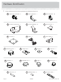
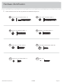
Hardware Identifi cation
å Screws are shown actual size. You may receive extra hardware with your unit.
412308 www.sauder.com/servicesPage 4
SAFETY BRACKET - 1
BB
ANGLE BRACKET - 20
CC
WASHER - 2
LL
GROMMET CAP - 2
OO
TWIST-LOCK® FASTENER - 4
AA
RUBBER SLEEVE - 12
SS
METAL PIN - 24
RR
MAGNETIC CATCH - 1
JJ
CORD CLIP - 2
MM
NN
GROMMET - 2
STRIKE PLATE - 1
KK
KNOB - 2
PP
HOLE PLUG - 2
QQ
TIE PLATE - 1
GG
VALANCE CONNECTOR - 2
DD
VALANCE BRACKET - 9
EE
VALANCE CLIP - 2
FF
PIVOT HINGE - 2
II
FELT DISC CARD - 1
TT
HH
HINGE - 4

Hardware Identifi cation
å Screws are shown actual size. You may receive extra hardware with your unit.
412308www.sauder.com/services
Page 5
BLACK 1-1/8" MACHINE SCREW - 2
WW
BLACK 9/16" LARGE HEAD SCREW - 65
ZZ
SILVER 7/8" PAN HEAD SCREW - 2
YY
BLACK 1-5/8" PAN HEAD SCREW - 2
VV
BLACK 1-7/8" FLAT HEAD SCREW - 25
UU
BROWN 1" FLAT HEAD SCREW - 4
XX
AAA
BLACK 1/2" FLAT HEAD SCREW - 9
BBB
NAIL - 55

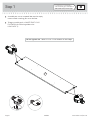
Step 1
Look for this icon. It means a
video assembly tip is available at
www.sauder.com/services/tips
å
Assemble your unit on a carpeted fl oor or on the empty
carton to avoid scratching your unit or the fl oor.
å
To begin assembly, push a SAUDER TWIST-LOCK®
FASTENER (AA) into the large holes in the
LONG SHELF (I).
412308 www.sauder.com/servicesPage 6
I
AA
AA
Do not tighten the TWIST-LOCK® FASTENERS in this step.

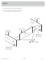
å
Insert four METAL PINS (RR) into the CENTER SHELF (J).
å
Insert the METAL PINS (RR) in the ends of the CENTER
SHELF (J) into the holes in the UPRIGHTS (E and F).
Step 2
412308www.sauder.com/services
Page 7
E
F
J
RR
Finished edge
Finished edge
Finished edge
Surface with
more holes
Surface with
fewer holes
Surface with holes
The large hole
should be here.
The large hole
should be here.
(4 used)

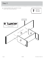
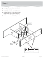
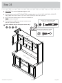
Step 3
å
Fasten the UPRIGHTS (E and F) to the TOP (H). Use four
BLACK 1-7/8" FLAT HEAD SCREWS (UU).
412308 www.sauder.com/servicesPage 8
E
F
H
Surface with fewer holes
Rounded edge
BLACK 1-7/8" FLAT HEAD SCREW
(4 used in this step)
UU
Remember:
Righty tighty.
Lefty loosey.

å
Insert eight METAL PINS (RR) into the DIVIDERS (G).
å
Insert the METAL PINS (RR) in one end of the
DIVIDERS (G) into the holes in the CENTER SHELF (J).
å
Fasten the LONG SHELF (I) to the UPRIGHTS (E and F).
Use four BLACK 1-7/8" FLAT HEAD SCREWS (UU).
å
NOTE: Be sure the METAL PINS in the DIVIDERS (G)
insert into the holes in the LONG SHELF (I).
Step 4
412308www.sauder.com/services
Page 9
RR
E
F
G
G
I
Surface with
TWIST-LOCK®
FASTENERS
Finished edge
J
BLACK 1-7/8" FLAT HEAD SCREW
(4 used in this step)
UU
(8 used)

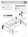
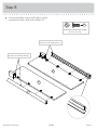
Step 5
å
Fasten the INNER ENDS (C and D) to the TOP (H). Use
four BLACK 1-7/8" FLAT HEAD SCREWS (UU).
å
NOTE: Be sure the dowel end of the TWIST-LOCK®
FASTENERS in the LONG SHELF (I) insert into the holes
in the INNER ENDS (C and D).
å
Fasten the LONG SHELF (I) to the INNER ENDS (C
and D). Tighten four TWIST-LOCK® FASTENERS.
412308 www.sauder.com/servicesPage 10
H
I
C
D
Surface with holes
Surface without holes
Finished edge
These edges
should be even.
BLACK 1-7/8" FLAT HEAD SCREW
(4 used in this step)
UU
How to use the SAUDER TWIST-LOCK
®
FASTENER
1. Insert the dowel end of the FASTENER into the hole
of the adjoining part.
NOTE: The dowel end of the FASTENER must remain
fully inserted in the hole of the adjoining part while
locking the FASTENER.
2. Tighten the FASTENER with a Phillips screwdriver as
tight as possible.
Dowel end

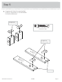
å
Fasten the HALF DISKS (Z) to the MOUNTING
PLATES (P) and PLINTHS (Y). Use four BROWN 1"
FLAT HEAD SCREWS (XX).
Step 6
412308www.sauder.com/services
Page 11
The larger hole
should be facing up.
Y
Y
Z
Z
Z
Z
P
Curved edge
Finished
surface
P
Finished
surface
BROWN 1" FLAT HEAD SCREW
(4 used in this step)
XX
The larger hole
should be facing up.

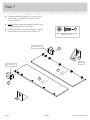
Step 7
å
Fasten twelve ANGLE BRACKETS (CC) to the OUTER
ENDS (A and B). Use twelve BLACK 9/16" LARGE
HEAD SCREWS (ZZ).
å
NOTE: Be sure the edges of the ANGLE BRACKETS are
even with the edges of the OUTER ENDS.
å
Fasten the PLINTHS (Y) to the OUTER ENDS (A and B).
Use four BLACK 9/16" LARGE HEAD SCREWS (ZZ).
412308 www.sauder.com/servicesPage 12
Y
Y
B
CC
CC
Z
Z
Surface
with holes
Use lower holes
Use lower holes
A
Surface
with holes
BLACK 9/16" LARGE HEAD SCREW
(16 used in this step)
ZZ
(12 used)

å
Fasten the MOLDINGS (X) to the OUTER ENDS (A and B).
Use eight BLACK 9/16" LARGE HEAD SCREWS (ZZ).
Step 8
412308www.sauder.com/services
Page 13
A
B
X
X
The MOLDING (X) should be
centered over the HALF DISK (Z).
The MOLDING (X) should be
centered over the HALF DISK (Z).
BLACK 9/16" LARGE HEAD SCREW
(8 used in this step)
ZZ

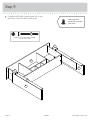
Step 9
å
Fasten the OUTER ENDS (A and B) to the TOP (H). Use
four BLACK 1-7/8" FLAT HEAD SCREWS (UU).
412308 www.sauder.com/servicesPage 14
A
B
H
X
X
Y
Y
BLACK 1-7/8" FLAT HEAD SCREW
(4 used in this step)
UU
Now might be a
good time to refresh
your drink.

å
Fasten the MOUNTING PLATES (P) to the OUTER
ENDS (A and B) and INNER ENDS (C and D). Use eight
BLACK 1-7/8" FLAT HEAD SCREWS (UU).
å
Push the CORD CLIPS (MM) into the holes in the
OUTER END (A).
å
NOTE: The CORD CLIP is used to manage your cords.
Step 10
412308www.sauder.com/services
Page 15
C
B
D
P
P
A
Curved edge
Curved edge
Surface without
HALF DISK
Surface without
HALF DISK
MM
BLACK 1-7/8" FLAT HEAD SCREW
(8 used in this step)
UU

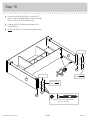
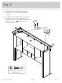
Step 11
å
Carefully turn your unit onto its top.
å
Fasten eight ANGLE BRACKETS (CC) to the TOP (H)
and LONG SHELF (I). Use eight BLACK 9/16" LARGE
HEAD SCREWS (ZZ).
å
Fasten the TOP MOLDING (W) to the TOP (H) and SHELF
MOLDING (T) to the LONG SHELF (I). Use eight BLACK
9/16" LARGE HEAD SCREWS (ZZ).
å
NOTE: There are no pre-drilled holes in the MOLDINGS.
The SCREWS will tighten into the groove.
412308 www.sauder.com/servicesPage 16
H
I
T
W
CC
BLACK 9/16" LARGE HEAD SCREW
(16 used in this step)
ZZ
(8 used)

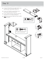
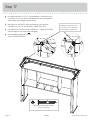
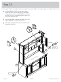
å
Fasten the TIE PLATE (GG) to the LONG SHELF (I). Use
two BLACK 9/16" LARGE HEAD SCREWS (ZZ).
å
Fasten a PIVOT HINGE (II) to the DOOR (M). Use a
BLACK 9/16" LARGE HEAD SCREW (ZZ).
å
Fasten a STRIKE PLATE (KK) to the SMALL DOOR (M).
Use a BLACK 1/2" FLAT HEAD SCREW (AAA).
å
NOTE: The surface of the STRIKE PLATE with "SAUDER"
should be facing up.
Step 12
412308www.sauder.com/services
Page 17
I
M
GG
II
KK
BLACK 9/16" LARGE HEAD SCREW
(3 used for the TIE PLATE)
ZZ
BLACK 1/2" FLAT HEAD SCREW
(1 used for the STRIKE PLATE)
AAA

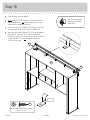
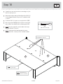
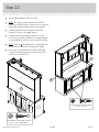
Step 13
å
Insert a PIVOT HINGE (II) into the TIE PLATE on the LONG SHELF (I).
å
Insert the PIVOT HINGE, which is fastened to the SMALL DOOR (M),
into both WASHERS (LL), and into the hole in the MOUNTING
PLATE (P). You will need to tilt your DOOR slightly.
å
Now, tip the SMALL DOOR in and fasten the free HINGE to the SMALL
DOOR. Use a BLACK 9/16" LARGE HEAD SCREW (ZZ).
å
NOTE: To make adjustments to the DOOR, loosen the SCREW in the
HINGE, make needed adjustments, and tighten the SCREW.
å
Push a MAGNETIC CATCH (JJ) into the hole in the
MOUNTING PLATE (P).
412308 www.sauder.com/servicesPage 18
I
M
P
II
LL
JJ
BLACK 9/16" LARGE HEAD SCREW
(1 used in this step)
ZZ

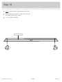
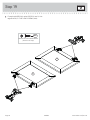
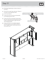
å
NOTE: Pay close attention to the positioning of the parts.
å
Slide two patented* VALANCE CONNECTORS (DD) onto
the FRONT VALANCE (Q) as shown.
å
* U.S. Patent No. 6,179,515B1
Step 14
412308www.sauder.com/services
Page 19
Q
Unfi nished surface
DD DD

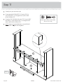
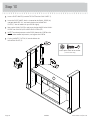
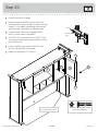
Step 15
å
Carefully stand your unit upright.
å
NOTE: Hold the FRONT VALANCE (Q) in place until this
step is completed. Do not allow the VALANCE to hang
freely until it is completely fastened.
å
Fasten the VALANCE CONNECTORS (DD) to the TOP (H).
Use two BLACK 9/16" LARGE HEAD SCREWS (ZZ).
å
Now, slip fi ve VALANCE BRACKETS (EE) into the groove
in the FRONT VALANCE (Q). Fasten the VALANCE
BRACKETS to the TOP (H). Use fi ve BLACK 9/16" LARGE
HEAD SCREWS (ZZ). Do not completely tighten the
SCREWS at this time.
412308 www.sauder.com/servicesPage 20
Q
H
EE
DD
DD
BLACK 9/16" LARGE HEAD SCREW
(7 used in this step)
ZZ
(5 used)
Pro Tip: Lift with your
legs. And, you know,
your arms.
La page charge ...
La page charge ...
La page charge ...
La page charge ...
La page charge ...
La page charge ...
La page charge ...
La page charge ...
La page charge ...
La page charge ...
La page charge ...
La page charge ...
La page charge ...
La page charge ...
La page charge ...
La page charge ...
La page charge ...
La page charge ...
La page charge ...
La page charge ...
-
 1
1
-
 2
2
-
 3
3
-
 4
4
-
 5
5
-
 6
6
-
 7
7
-
 8
8
-
 9
9
-
 10
10
-
 11
11
-
 12
12
-
 13
13
-
 14
14
-
 15
15
-
 16
16
-
 17
17
-
 18
18
-
 19
19
-
 20
20
-
 21
21
-
 22
22
-
 23
23
-
 24
24
-
 25
25
-
 26
26
-
 27
27
-
 28
28
-
 29
29
-
 30
30
-
 31
31
-
 32
32
-
 33
33
-
 34
34
-
 35
35
-
 36
36
-
 37
37
-
 38
38
-
 39
39
-
 40
40


Sauder Palladia Hutch 412308 Mode d'emploi
- Taper
- Mode d'emploi
dans d''autres langues
Documents connexes
-
Sauder HomePlus Collection 411967 Mode d'emploi
-
-
-
-
-
-
-
Sauder 416967 Guide d'installation
-
-