Sauder 409048 Assembly Instructions Manual
- Taper
- Assembly Instructions Manual

04 / 09 / 13
Lot #: 352229
Date Purchased:
409048
Assembly Instructions
Instructions d’assemblage
Instrucciones de Ensamblaje
DO NOT RETURN YOUR UNIT TO THE STORE
Contact us first
NE PAS RAPPORTER L’ÉLÉMENT AU MAGASIN
Nous contacter en premier
NO DEVUELVA SU UNIDAD A LA TIENDA
Comuníquese con nosotros primero
This instruction booklet contains important safety information.
Please read and keep for future reference.
NOTE
Este folleto de instrucciones contiene información importante sobre la seguridad.
Por favor lea y guárdelo para referencia en el futuro.
NOTA
Ce manuel d’instructions contient d’importantes informations relatives à la sécurité.
À lire et conserver pour toute référence future.
REMARQUE
www.sauder.com
For immediate service, our website is available
24 hours a day, 7 days a week
to order replacement parts, access assembly tips,
register your product, and view Sauder products.
Most replacement parts ship from our
facility in one or two business days.
Les pièces de rechange sont, pour la plupart, expédiées de
notre établissement dans les un à deux jours ouvrables.
La mayoría de piezas de repuesto son enviadas desde
nuestra instalación en uno o dos días laborables.
Mon-Fri -- 9am-5:30pm ET
United States and Canada (except holidays)
Consumer Services 1--800--523--3987
register your new purchase online
www.sauder.com
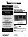
Entertainment Credenza
Meuble Télévision/Vidéo/Stéréo
Centro de Entretenimiento
Pour obtenir une service immédiate, notre site Internet
est disponible 24 heures sur 24, 7 jours sur 7,
pour commander des pièces de rechange,
des conseils d’assemblage, enregistrer tout produit
ou visualiser des produits Sauder.
Du lundi au vendredi de9h00à17h30
(heure normale de l’est)
Aux États--Unis et au Canada (sauf jours fériés)
Services aux consommateurs 1--800--523--3987
Para el servicio inmediata, nuestro sitio Web está
disponible las 24 horas al día,
7 días a la semana para pedir piezas de repuesto,
consejos de ensamblaje, registrar su producto y
ver los productos Sauder.
De lunes a viernes de 9 a.m. a 5:30 p.m. (hora del este)
Estados Unidos y Canadá (salvo días festivos)
Servicios del consumidor 1 --800--523--3987
The Edge Water Collection
La Collection Edge Water
La Colección Edge Water

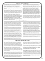
This Sauder unit is designed for use with televisions weighing not more than 95 pounds. Use of a TV that is too large or too heavy is
hazardous. Severe injury or death can occur because the TV and furniture combination will be unstable, and may tip over.
S Check the size and weight of your TV. Compare it to the size diagram below -- before you begin assembly.
S Make sure that the base of the TV can set completely on the TV shelf. The TV base should never extend past the
edge of the TV shelf. (The picture tube cone may extend past the shelf.)
S Never use a TV that is too heavy or too large.
S Be sure to apply the warning label as instructed in the last step. The label provides important safety related TV weight
information.
Cet élément Sauder est conçu pour être utilisé avec des téléviseurs ne pesant pas plus de 43 kg. L’utilisation d’un téléviseur trop
large ou trop lourd est dangereuse. Cette combinaison téléviseur et meuble instable risque de provoquer des blessures graves, voire
mortelles, et de se renverser.
S Vérifier la taille et le poids du téléviseur. La comparer au diagramme de tailles ci--dessous avant de commencer l’assemblage.
S S’assurer que la base du téléviseur soit bien installée sur la tablette de téléviseur. La base du téléviseur ne doit jamais dépasser
le bord de la tablette de téléviseur. (Le cône du tube cathodique peut dépasser la tablette.)
S Ne jamais utiliser un téléviseur qui soit trop lourd ou trop large.
S Veiller à installer l’étiquette de mise en garde comme il l’est indiqué à la dernière étape. L’étiquette fournit d’importants
consignes de sécurité concernant le poids des téléviseurs.
Esta unidad Sauder está diseñada para el uso con televisores que pesan 43 kg o menos. El uso de un televisor demasiado grande o
demasiado pesado es peligroso. Existe un riesgo de lesiones graves o la muerte por la inestabilidad de la combinación de televisor y
mobiliario que pueda inclinar y caerse.
S Verifique el tamaño y el peso del televisor. Compárelo al diagrama de tamaño abajo antes de comenzar el ensamblaje.
S Asegúrese que la base del televisor puede colocarse completamente sobre el estante televisor. La base del televisor nunca debe
extenderse sobre el borde del estante televisor. (El cono del tubo de imagen puede extenderse sobre el estante.)
S Nunca use un televisor que es demasiado pesado o demasiado grande.
S Asegúrese de instalar la Etiqueta de Advertencia tal como se instruye en el último paso. La etiqueta proporciona información
importante de seguridad en cuanto al peso del televisor.
ADVERTENCIA
409048
WARNING
AVERTISSEMENT
18”
45.7 cm
58--3/4”
149.2 cm
95 lbs.
43 kg.

409048
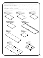
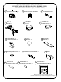
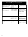
PARTS IDENTIFICATION: Each part for this unit may not have a label or inked letter on it. Use this PARTS
IDENTIFICATION page, the labels, and the inked letters to help distinguish similar parts from each other.
IDENTIFICATION DES PIÈCES : Les pièces de cet élément ne comportent peut--être pas toutes une
étiquette ou une lettre imprimée. Utiliser cette page IDENTIFICATION DES PIÈCES, les étiquettes et les lettres
imprimées pour faciliter l’identification des pièces semblables.
IDENTIFICACIÓN DE LAS PARTES: Cada pieza para esta unidad puede que no tenga una etiqueta o una
letra entintada. Use esta página IDENTIFICACIÓN DE LAS PARTES, etiquetas y las letras entintadas para ayudar
a identificar piezas similares.
RIGHT UPRIGHT -- 1
MONTANT DROIT -- 1
PARAL DERECHO -- 1
RIGHT END -- 1
EXTRÉMITÉ DROITE -- 1
EXTREMO DERECHO -- 1
LEFT END -- 1
EXTRÉMITÉ GAUCHE -- 1
EXTREMO IZQUIERDO -- 1
A B C
TOP -- 1
DESSUS -- 1
PANEL SUPERIOR -- 1
LEFT UPRIGHT -- 1
MONTANT GAUCHE -- 1
PARAL IZQUIERDO -- 1
D E
SHELF -- 1
TABLETTE -- 1
ESTANTE -- 1
BOTTOM -- 1
DESSOUS -- 1
FONDO -- 1
F G
DOOR -- 2
PORTE -- 2
PUERTA -- 2
BACK -- 1
ARRIÈRE -- 1
DORSO -- 1
H I

409048
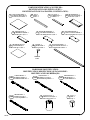
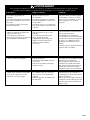
PARTS IDENTIFICATION (CONTINUED):
IDENTIFICATION DES PIÈCES (SUITE) :
IDENTIFICACIÓN DE LAS PARTES (CONTINUACIÓN):
ADJUSTABLE SHELF -- 5
TABLETTE RÉGLABLE -- 5
ESTANTE AJUSTABLE -- 5
J
LEG -- 2
PIED -- 2
PATA -- 2
K
VALANCE -- 1
LAMBREQUIN -- 1
CORNISA -- 1
L
DRAWER FRONT -- 1
DEVANT DE TIROIR -- 1
CARA DE CAJÓN -- 1
M
DRAWER BACK -- 1
ARRIÈRE DE TIROIR -- 1
DORSO DE CAJÓN -- 1
N
RIGHT DRAWER SIDE -- 1
CÔTÉ DROIT DE TIROIR -- 1
LADO DERECHO DE CAJÓN -- 1
O
LEFT DRAWER SIDE -- 1
CÔTÉ GAUCHE DE TIROIR -- 1
LADO IZQUIERDO DE CAJÓN -- 1
P
DRAWER BOTTOM -- 1
FOND DE TIROIR -- 1
FONDO DE CAJÓN -- 1
Q
SPACER -- 2
SÉPARATEUR -- 2
ESPACIADOR -- 2
R
BOTTOM MOLDING -- 1
MOULURE DE DESSOUS -- 1
MOLDURA DE FONDO -- 1
S
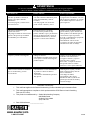
HARDWARE IDENTIFICATION:
IDENTIFICATION DES PIÈCES DE QUINCAILLERIE :
IDENTIFICACIÓN DE HERRAJES:
PLASTIC FOOT -- 2
PIED EN PLASTIQUE -- 2
PATA EN PLÁSTICO -- 2
X
FOOT -- 2
PIED -- 2
PATA -- 2
Y
35DA 35DB 35DC
35DD
DRAWER RIGHT -- 1
TIROIR DROIT -- 1
CAJÓN DERECHO -- 1
CABINET RIGHT -- 1
ÉLÉMENT DROITE -- 1
GABINETE DERECHO -- 1
CABINET LEFT -- 1
ÉLÉMENT GAUCHE -- 1
GABINETE IZQUIERDO -- 1
DRAWER LEFT -- 1
TIROIR GAUCHE -- 1
CAJÓN IZQUIERDO -- 1
HIDDEN
PART

409048
HARDWARE IDENTIFICATION (CONTINUED):
IDENTIFICATION DES PIÈCES DE QUINCAILLERIE (SUITE) :
IDENTIFICACIÓN DE HERRAJES (CONTINUACIÓN):
WARNING LABEL -- 1
ÉTIQUETTE DE MISE EN GARDE -- 1
ETIQUETA DE ADVERTENCIA -- 1
(Refer to the last step for proper location and application)
(Consulter la dernière étape pour l’emplacement et application appropriées)
(Consulte el último paso para la ubicación e instalación apropiada)
NN
TWIST-LOCKR FASTENER -- 16
FIXATION TWIST–LOCK
R
-- 1 6
SUJETADOR TWIST–LOCK
R
-- 1 6
Z
HIDDEN CAM -- 4
EXCENTRIQUE ESCAMOTABLE -- 4
EXCÉNTRICO ESCONDIDO -- 4
1F
CAM SCREW -- 4
VIS D’EXCENTRIQUE -- 4
BIELA DE EXCÉNTRICO -- 4
8F
HINGE -- 4
CHARNIÈRE -- 4
BISAGRA -- 4
CC
GROMMET -- 1
PASSE--CÂBLES -- 1
OJAL -- 1
DD
GROMMET CAP -- 1
COUVERCLE DE PASSE--CÂBLES -- 1
CUBIERTA DE OJAL -- 1
EE
ANGLE BRACKET -- 6
CONSOLE À ÉQUERRE -- 6
SOPORTE ANGULAR -- 6
FF
PULL -- 4
POIGNÉE - 4
TIRADOR - 4
GG
BACKPLATE -- 2
FERRURE -- 2
PLACA DE TIRADOR -- 2
HH
SLIDE CAM -- 2
EXCENTRIQUE DE COULISSE -- 2
EXCÉNTRICO DE CORREDERA -- 2
II
FELT DISC CARD -- 1
FICHE DE TAMPONS EN FEUTRE - 1
TARJETA CON TOPES DE FIELTRO - 1
JJ
CLIP -- 2
CLIP -- 2
GRAPA -- 2
KK
METAL PIN -- 20
GOUPILLE EN MÉTAL -- 20
ESPIGA DE METAL -- 20
LL
RUBBER SLEEVE -- 20
MANCHON EN CAOUTCHOUC -- 20
MANGUITO DE GOMA -- 20
MM

409048
BLACK 1--7/8” FLAT HEAD SCREW -- 4
VIS NOIRE TÊTE PLATE 48 mm -- 4
TORNILLO NEGRO DE CABEZA PERDIDA de 48 mm -- 4
BLACK 1--5/8” PAN HEAD SCREW -- 2
VIS NOIRE TÊTE GOUTTE DE SUIF 41 mm -- 2
TORNILLO NEGRO DE CABEZA REDONDA de 41 mm -- 2
1
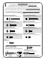
NOTE / REMARQUE / NOTA:
Using a SCREW that is too long will cause damage. Before beginning assembly, separate
each type of SCREW. Carefully study the SCREW diagrams below (SHOWN ACTUAL SIZE
).
Pay close attention to the color of each SCREW. You may receive extra hardware with your unit.
L’usage d’une VIS trop longue peut endommager l’élément. Avant de commencer l’assemblage, séparer chaque
type de VIS. Attentivement, réviser les schémas des VIS ci--dessous (VIS ILLUSTRÉES GRANDEUR NATURE
).
Faire attention à la couleur de chaque VIS. Il est possible que unes pièces supplémentaires sont incluses avec l’élément.
El uso de un TORNILLO demasiado largo causará daño. Antes de comenzar el ensamblaje, separe cada tipo de TORNILLO.
Atentamente estudie los diagramas de TORNILLO abajo (TORNILLOS MOSTRADOS EN TAMAÑO REAL
).
Preste cuidadosa atención al color de cada TORNILLO. Es posible que se incluyen unas piezas de herraje suplementarias
con la unidad.
OO PP
SS TT
UU VV
BLACK 1--1/8” MACHINE SCREW -- 2
VIS NOIRE À MÉTAUX 28 mm -- 2
TORNILLO NEGRO PARA METAL de 28 mm -- 2
BROWN 1” FLAT HEAD SCREW -- 4
VIS MARRON TÊTE PLATE 25 mm -- 4
TORNILLO MARRÓN DE CABEZA PERDIDA de 25 mm -- 4
QQ RR
BLACK 7/8” MACHINE SCREW -- 2
VIS NOIRE À MÉTAUX 22 mm -- 2
TORNILLO NEGRO PARA METAL de 22 mm -- 2
BLACK 9/16” LARGE HEAD SCREW -- 12
VIS NOIRE TÊTE LARGE 14 mm -- 12
TORNILLO NEGRO DE CABEZA GRANDE de 14 mm -- 12
BLACK 1/2” FLAT HEAD SCREW -- 8
VIS NOIRE TÊTE PLATE 13 mm -- 8
TORNILLO NEGRO DE CABEZA PERDIDA de 13 mm -- 8
GOLD 5/16” FLAT HEAD SCREW -- 8
VIS DORÉE TÊTE PLATE 8 mm -- 8
TORNILLO DORADO DE CABEZA PERDIDA de 8 mm -- 8
WW
NAIL -- 44
CLOU -- 44
CLAVO -- 44
ASSEMBLY TOOLS REQUIRED
OUTILS D’ASSEMBLAGE REQUIS
HERRAMIENTAS DE ENSAMBLAJE REQUERIDAS
TIP SHOWN ACTUAL SIZE
POINTE GRANDEUR NATURE
PUNTA MOSTRADA EN TAMAÑO REAL
HAMMER
MARTEAU
MARTILLO
NO. 2 PHILLIPS SCREWDRIVER
TOURNEVIS À TÊTE CRUCIFORME PHILLIPS n_2
DESTORNILLADOR PHILLIPS (CRUZ) No. 2

2
409048
A
B
www.sauder. com/services
Assembler l’élément sur un sol à
moquette ou sur le carton vide pour éviter
d’endommager l’élément ou le sol.
- Pour commencer l’assemblage,
enfoncer une FIXATION
TWIST--LOCK
R
SAUDER (Z) dans les
gros trous de l’EXTRÉMITÉ
DROITE (A) et l’EXTRÉMITÉ
GAUCHE (B). Répéter cette étape pour
les MONTANTS (C et D), le
DESSOUS (F) et la TABLETTE (G).
REMARQUE
: Ne pas serrer les
FIXATIONS TWIST--LOCK
R
àcestade
de l’assemblage.
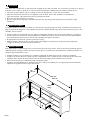
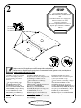
Assemble your unit on a carpeted
floor or on the empty carton to
avoid scratching your unit or
the floor.
- To begin assembly, push a
SAUDER TWIST-LOCK
R
FASTENER (Z) into the large
holes in the RIGHT END (A) and
LEFT END (B). Repeat this step
for the UPRIGHTS (C and D),
BOTTOM (F), and SHELF (G).
NOTE
: Do not tighten the
TWIST-LOCK
R
FASTENERS at
this time.
Ensamble la unidad sobre un piso
alfombrado o sobre el cartón vacío para
evitar rayar la unidad o el piso.
- Para comenzar el ensamblaje, empuje
un SUJETADOR TWIST--LOCK
R
SAUDER (Z) dentro de los agujeros
grandes del EXTREMO DERECHO (A) y
del EXTREMO IZQUIERDO (B). Repita
este paso para los PARALES (C y D), el
FONDO (F) y el ESTANTE (G).
NOTA
: No apriete los SUJETADORES
TWIST--LOCK
R
por ahora.
Look for this icon. It means a video assembly tip is available at:
Repérer cette icône. Elle signifie qu’un conseil de montage vidéo est disponible à :
Busque este icono. Significa que un consejo práctico para ensamble de muebles, grabado en video, está disponible en:
www.sauder.com/services/tips
Z
(16 used)
(16 utilisées)
(16 utilizados)
If you purchased the 409049
TV Wall with Bracket, assemble that unit
first.
Si le Mur Télévision avec support pour
téléviseur 409049 a été acheté,
l’assembler en premier.
Si usted compró el Mural Televisión con
Soporte para TV 409049, ensámblelo
primero.
STOP
STOP

3
409048
www.sauder. com/services
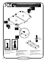
Do not tighten the HIDDEN CAMS in this step.
Ne pas
serrer les EXCENTRIQUES ESCAMOTABLES à cette étape.
No
apriete los EXCÉNTRICOS ESCONDIDOS en este paso.
A
B
Arrow
Flèche
Flecha
Arrow
Flèche
Flecha
Arrow
Flèche
Flecha
Hole
Trou
Agujero
- Push four HIDDEN CAMS (1F)
into the ENDS (A and B).
- Turn four CAM SCREWS (8F)
into the LEGS (K).
- Empuje cuatro EXCÉNTRICOS
ESCONDIDOS (1F) dentro de los
EXTREMOS (A y B).
- Atornille cuatro BIELAS DE
EXCÉNTRICO (8F) dentro de las PATAS
(K).
- Enfoncer quatre EXCENTRIQUES
ESCAMOTABLES (1F) dans les
EXTRÉMITÉS (A et B).
- Faire tourner quatre VIS
D’EXCENTRIQUE (8F) dans les
PIEDS (K).
K
K
(4 used)
(4 utilisées)
(4 utilizadas)
8F
1F
1F

4
409048
www.sauder. com/services
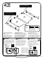
- Fasten the LEGS (K) to the
ENDS (A and B). Tighten four
HIDDEN CAMS.
- Fasten the FEET (Y) to the
LEGS (K). Use two BLACK 1--5/8”
PANHEADSCREWS(PP).
- Fije las PATAS (K) a los
EXTREMOS (A y B). Apriete cuatro
EXCÉNTRICOS ESCONDIDOS.
- Fije las PATAS (Y) a las PATAS (K).
Utilice dos TORNILLOS NEGROS DE
CABEZA REDONDA de 41 mm (PP).
- Fixer les PIEDS (K) aux
EXTRÉMITÉS (A et B). Serrer quatre
EXCENTRIQUES ESCAMOTABLES.
- Fixer les PIEDS (Y) aux PIEDS (K).
Utiliser deux VIS NOIRES TÊTE
GOUTTE DE SUIF 41 mm (PP).
2usedinthisstep
2 utilisées à cette étape
2 utilizados en este paso
Black
Noire
Negro
PP
A
B
K
K
Y
Y
These surfaces should be even.
Ces surfaces devraient être à fleur.
Estas superficies deben estar niveladas.
These surfaces should be even.
Ces surfaces devraient être à fleur.
Estas superficies deben estar niveladas.
Caution
Risk of damage or injury. Hidden Cams
must be completely tightened. Hidden
Cams that are not completely tightened
may loosen, and parts may separate.
Turn the hidden cam 210 degrees to
completely tighten it.
Precaución
Riesgo de daños o heridas. Los
Excéntricos Escondidos deben a
pretarse completamente. Los Excéntricos
Escondidos que no se aprieten
completamente se aflojarán y las
partes pueden separarse. Para apretar
completamente, atornille el excéntrico
escondido 210 grados.
Attention
Risque des dégâts ou blessures. Les
Excentriques Escamotables doivent
être serrés à bloc. Les Excentriques
Escamotables que ne sont pas serrées
à par bloc peuvent desserrer et les
piées peuvent séarer. Pour serrer à
bloc, faire tourner l’excentrique
escamotable de 210 degrés.
Arrow
Flèche
Flecha
Arrow
Flèche
Flecha
Maximum 210 degrees
Maximum de 210 degrés
Máximo de 210 grados
Minimum 190 degrees
Minimum de 190 degrés
Mínimo de 190 grados
Tighten
Serrer
Apriete
Start
Commencer
Comience

5
409048
www.sauder. com/services
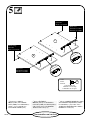
- Fasten the CABINET
RIGHT (35DA) and CABINET
LEFT (35DB) to the UPRIGHTS (C
and D). Use four GOLD 5/16”
FLAT HEAD SCREWS (VV).
- Fije el GABINETE DERECHO (35DA)
y el GABINETE IZQUIERDO (35DB) a
los PARALES (C y D). Utilice cuatro
TORNILLOS DORADOS DE CABEZA
PERDIDA de 8 mm (VV).
- Fixer l’ÉLÉMENT
DROITE (35DA) et l’ÉLÉMENTS
GAUCHE (35DB) aux MONTANTS (C
et D). Utiliser quatre VIS DORÉES
TÊTE PLATE 8 mm (VV).
4usedinthisstep
4 utilisées à cette étape
4 utilizados en este paso
Gold
Dorée
Dorado
VV
C
D
Roller end
Extrémité à roulette
Extremo con rodillo
Finished edge
Chant fini
Borde con acabado
Roller end
Extrémité à roulette
Extremo con rodillo
Finished edge
Chant fini
Borde con acabado

6
409048
www.sauder. com/services
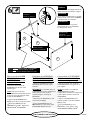
How to use the SAUDER
TWIST-LOCK
R
FASTENER (Refer to the
enlarged diagram.)
1. Insert the dowel end of the
FASTENER into the hole of the
adjoining part.
NOTE
: The dowel end of the
FASTENER must remain fully inserted
in the hole of the adjoining part while
locking the FASTENER.
2. Tighten the FASTENER with a
Phillips screwdriver as tight as possible.
- Fasten the SHELF (G) to the
UPRIGHTS (C and D). Tighten four
TWIST-LOCK
R
FASTENERS.
Cómo utilizar el SUJETADOR
TWIST--LOCKR SAUDER
(Refiérase al diagrama ampliado.)
1. Inserte el extremo con cabilla del
SUJETADOR dentro del agujero de la
parte adjunta.
NOTA:
El extremo con cabilla del
SUJETADOR debe quedarse
completamente insertado en el agujero de
la parte adjunta cuando se enclava el
SUJETADOR.
2. Apriete el SUJETADOR lo más
apretado posible con un destornillador
Phillips (cruz).
- Fije el ESTANTE (G) a los
PARALES (C y D). Apriete cuatro
SUJETADORES TWIST--LOCK
R
.
Utilisation de la FIXATION
TWIST--LOCKR SAUDER
(Consulter le schéma agrandi.)
1. Insérer l’extrémité filetée de la
FIXATION dans le trou de la pièce
attenante.
REMARQUE
: L’extrémité filetée de
la FIXATION doit rester complètement
inséréedansletroudelapièce
attenante lorsque l’on bloque la
FIXATION.
2. Bien serrer la FIXATION à l’aide
d’un tournevis Phillips.
- Fixer la TABLETTE (G) aux
MONTANTS (C et D). Serrer quatre
FIXATIONS TWIST--LOCK
R
.
Do not stand the unit upright without the
BACK fastened. The unit may collapse.
No coloque la unidad en posición
vertical hasta que se fije el DORSO.
La unidad podría caerse.
Ne pas relever l’élément dans sa position
verticale avant d’avoir fixé l’ARRIÈRE.
L’élément risque de s’effondrer.
Caution
Attention
Precaución
C
D
G
Finished edge
Chant fini
Borde con acabado
Finished edge
Chant fini
Borde con acabado
Unfinished surface
Surface non finie
Superficie sin acabado
Surface without TWIST-LOCK
R
FASTENERS
Surface sans
FIXATIONS TWIST--LOCK
R
Superficie sin SUJETADORES TWIST--LOCK
R

7
409048
www.sauder. com/services
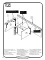
- Fasten the LEFT END (B) to the
TOP (E). Tighten two TWIST-LOCK
R
FASTENERS.
- Fasten the UPRIGHTS (C and D) to
the TOP (E). Tighten four
TWIST-LOCK
R
FASTENERS.
- Fije el EXTREMO IZQUIERDO (B)
al PANEL SUPERIOR (E). Apriete dos
SUJETADORES TWIST--LOCK
R
.
- Fije los PARALES (C y D) al PANEL
SUPERIOR (E). Apriete cuatro
SUJETADORES TWIST--LOCK
R
.
- Fixer l’EXTRÉMITÉ
GAUCHE (B) au DESSUS (E). Serrer
deux FIXATIONS TWIST--LOCK
R
.
- Fixer les MONTANTS (C et D) au
DESSUS (E). Serrer quatre
FIXATIONS TWIST--LOCK
R
.
C
D
E
B
Leg
Pied
Pata
Unfinished surface
Surface non finie
Superficie sin acabado
Finished edge
Chant fini
Borde con acabado
Molding
Moulure
Moldura
These surfaces should be even.
Ces surfaces devraient être à fleur.
Estas superficies deben estar niveladas.

8
409048
www.sauder. com/services
- Fasten the BOTTOM (F) to the LEFT
END (B). Tighten two TWIST-LOCK
R
FASTENERS.
- Fasten the BOTTOM (F) to the
UPRIGHTS (C and D). Use four
BLACK 1--7/8” FLAT HEAD
SCREWS (OO).
- Fije el FONDO (F) al EXTREMO
IZQUIERDO (B). Apriete dos
SUJETADORES TWIST--LOCK
R
.
- Fije el FONDO (F) a los PARALES (C
y D). Utilice cuatro TORNILLOS
NEGROS DE CABEZA PERDIDA de
48 mm (OO).
- Fixer le DESSOUS (F) à
l’EXTRÉMITÉ GAUCHE (B). Serrer
deux FIXATIONS TWIST--LOCK
R
.
- Fixer le DESSOUS (F) aux
MONTANTS (C et D). Utiliser quatre
VIS NOIRES TÊTE PLATE
48 mm (OO).
C
D
B
F
4usedinthisstep
4 utilisées à cette étape
4 utilizados en este paso
Black
Noire
Negro
OO
Unfinished surface
Surface non finie
Superficie sin acabado
These holes must be here.
Ces trous devraient être ici.
Estos agujeros deben estar aquí.

9
409048
www.sauder. com/services
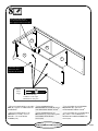
- Fasten the RIGHT END (A) to the
TOP (E) and BOTTOM (F). Tighten
four TWIST-LOCK
R
FASTENERS.
- Fije el EXTREMO DERECHO (A) al
PANEL SUPERIOR (E) y al FONDO (F).
Apriete cuatro SUJETADORES
TWIST--LOCK
R
.
- Fixer l’EXTRÉMITÉ DROITE (A)
au DESSUS (E) et au DESSOUS (F).
Serrer quatre FIXATIONS
TWIST--LOCK
R
.
F
A
E
Leg
Pied
Pata
These surfaces should be even.
Ces surfaces devraient être à fleur.
Estas superficies deben estar niveladas.

10
409048
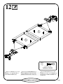
www.sauder. com/services
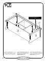
- Fixer six CONSOLES À
ÉQUERRE (FF) au DESSOUS (F) et au
LAMBREQUIN (L). Utiliser six VIS
NOIRES TÊTE LARGE 14 mm (TT).
REMARQUE : S’assurer que les chants
des CONSOLES À ÉQUERRE sont à
fleur des chants du DESSOUS et du
LAMBREQUIN.
- Fixer la MOULURE DE
DESSOUS (S) au DESSOUS (F). Utiliser
quatre VIS NOIRES TÊTE LARGE
14 mm (TT).
- Fixer le LAMBREQUIN (L) au
DESSUS (E). Utiliser deux VIS NOIRES
TÊTE LARGE 14 mm (TT).
- Fasten six ANGLE
BRACKETS (FF) to the
BOTTOM (F) and VALANCE (L).
Use six BLACK 9/16” LARGE
HEAD SCREWS (TT).
NOTE
: Be sure the edges of the
ANGLE BRACKETS are even
with the edges of the BOTTOM
and VALANCE.
- Fasten the BOTTOM
MOLDING (S) to the BOTTOM (F).
Use four BLACK 9/16” LARGE
HEAD SCREWS (TT).
- Fasten the VALANCE (L) to the
TOP (E). Use two BLACK 9/16”
LARGE HEAD SCREWS (TT).
- Fije seis SOPORTES
ANGULARES (FF) al FONDO (F) y a la
CORNISA (L). Utilice seis TORNILLOS
NEGROS DE CABEZA GRANDE de
14 mm (TT).
NOTA
: Asegúrese que los bordes de los
SOPORTES ANGULARES estén
nivelados con los bordes del FONDO y de
la CORNISA.
- Fije la MOLDURA DE FONDO (S) al
FONDO (F). Utilice cuatro TORNILLOS
NEGROS DE CABEZA GRANDE de
14 mm (TT).
- Fije la CORNISA (L) al PANEL
SUPERIOR (E). Utilice dos TORNILLOS
NEGROS DE CABEZA GRANDE de
14 mm (TT).
12 used in this step
12 utilisées à cette étape
12 utilizados en este paso
Black
Noire
Negro
TT
F
E
L
S
FF
(6 used)
(6 utilisées)
(6 utilizados)
FF
L
Curved edge
Chant arrondi
Borde redondeado

11
409048
www.sauder. com/services
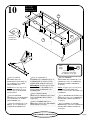
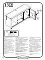
- Carefully turn your unit over onto
its front edges. Unfold the
BACK (H) and lay it over your unit.
- Make equal margins along all
four edges of the BACK (H). Push
on opposite corners of your unit if
needed to make it “square”.
- Fasten the BACK (H) to your
unit using the NAILS (WW).
NOTE
: Be sure to tap NAILS into
the holes that line up over the
UPRIGHTS (C and D).
NOTE
: Perforations have been
provided for access through the
BACK. Carefully cut out the holes
needed.
- Fasten the SPACERS (R) to the
BOTTOM (F). Use four BROWN
1” FLAT HEAD SCREWS (RR).
- Push the PLASTIC FEET (X)
into the holes in the SPACERS (R).
- Cuidadosamente voltee la unidad para
que repose sobre los bordes delanteros.
Desdoble el DORSO (H) y colóquelo
sobre la unidad.
- Fije el DORSO (H) de manera que los
márgenes son iguales a lo largo de los
cuatro bordes. Empuje sobre las esquinas
opuestas de la unidad si es requerido para
hacerla “cuadrada.”
- Fije el DORSO (H) a la unidad
utilizando los CLAVOS (WW).
NOTA
: Asegúrese de clavar ligeramente
los CLAVOS dentro de los agujeros que
se alinean sobre los PARALES (C y D).
NOTA
: Hay perforaciones provistas para el
acceso a través del DORSO.
Cuidadosamente corte los agujeros
requeridos.
- Fije los ESPACIADORES (R) al
FONDO (F). Utilice cuatro TORNILLOS
MARRONES DE CABEZA PERDIDA
de 25 mm (RR).
- EmpujelaPATAENPLÁSTICO(X)
dentro de los agujeros de los
ESPACIADORES (R).
- Avec précaution, retourner
l’élément sur ses chants avant.
Déplier l’ARRIÈRE (H) et le placer
sur l’élément.
- Veiller à avoir des marges égales le long
des quatre chants de l’ARRIÈRE (H). Si
besoin est, enfoncer sur les coins opposés de
l’élément pour s’assurer d’être « d’équerre ».
- Fixer l’ARRIÈRE (H) à l’élément en
utilisant les CLOUS (WW).
REMARQUE
: S’assurer de bien
enfoncer les CLOUS dans les trous qui
sont alignés sur les MONTANTS (C et D).
REMARQUE
: Des lignes perforées ont
été prévues pour accéder facilement à
l’ARRIÈRE. Découper avec précaution
les trous nécessaires.
- Fixer les SÉPARATEURS (R) au
DESSOUS (F). Utiliser quatre VIS
MARRON TÊTE PLATE 25 mm (RR).
- Insérer le PIED EN PLASTIQUE (X)
dans les trous dans les SÉPARATEURS (R).
42 used in this step
42 utilisés à cette étape
42 utilizados en este paso
WW
Do not stand the unit upright without the
BACK fastened. The unit may collapse.
No coloque la unidad en posición
vertical hasta que se fije el DORSO.
La unidad podría caerse.
Ne pas relever l’élément dans sa position
verticale avant d’avoir fixé l’ARRIÈRE.
L’élément risque de s’effondrer.
Caution
Attention
Precaución
These holes must line up over the UPRIGHTS.
Ces trous devraient être alignés sur les MONTANTS.
Estos agujeros deben alinearse sobre los PARALES.
F
4usedfortheSPACERS
4 utilisées pour les SÉPARATEURS
4 utilizados para los ESPACIADORES
Brown
Marron
Marr
Ón
RR
H
Unfinished surface
Surface non finie
Superficie sin acabado
X
X
R
HIDDEN PART
USING RECYCLED
MATERIAL
Color may vary.
HIDDEN PART
USING RECYCLED
MATERIAL
Color may vary.

12
409048
www.sauder. com/services
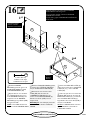
- Fasten two HINGES (CC) to each
DOOR (I). Use eight BLACK 1/2”
FLAT HEAD SCREWS (UU).
- Fije dos BISAGRAS (CC) a cada
PUERTA (I). Utilice ocho TORNILLOS
NEGROS DE CABEZA PERDIDA de
13 mm (UU).
- Fixer deux CHARNIÈRES (CC) à
chaque PORTE (I). Utiliser huit VIS
NOIRES TÊTE PLATE 13 mm (UU).
8usedinthisstep
8 utilisées à cette étape
8 utilizados en este paso
Black
Noire
Negro
UU
I
I
CC
CC

13
409048
www.sauder. com/services
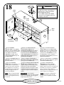
- Carefully stand your unit
upright.
- Fasten a DOOR (I) to the
RIGHT END (A). Use the screws
provided in the HINGES. See the
next step for adjustments.
- Fasten a PULL (GG) and
BACKPLATE (HH) to the
DOOR (I). Use a BLACK 1--1/8”
MACHINE SCREW (QQ).
- Peel the FELT DISC from the
FELT DISC CARD (JJ). Stick a
FELT DISC on the DOOR where it
comes in contact with the RIGHT
UPRIGHT (C).
- Repeat this step for the other
DOOR (I).
- Cuidadosamente ponga la unidad en
posición vertical.
- Fije una PUERTA (I) al EXTREMO
DERECHO (A). Utilice los tornillos
provistos de las BISAGRAS. Consulte el
próximo paso para los ajustes.
- Fije un TIRADOR (GG) y una
PLACA DE TIRADOR (HH) a la
PUERTA (I). Utilice un TORNILLO
NEGRO PARA METAL de 28 mm (QQ).
- Separe el TOPE DE FIELTRO de la
TARJETA CON TOPES DE
FIELTRO (JJ). Aplique un TOPE DE
FIELTRO sobre la PUERTA por donde
hace contacto con el PARAL
DERECHO (C).
- Repita este paso para la otra
PUERTA (I).
- Relever, avec précaution, l’élément
dans sa position verticale.
- Fixer une PORTE (I) à l’EXTRÉMITÉ
DROITE (A). Utiliser les vis fournies
avec les CHARNIÈRES. Voir l’étape
suivante pour réglages.
- Fixer une POIGNÉE (GG) et
FERRURE (HH) à la PORTE (I). Utiliser
une VIS NOIRE À MÉTAUX
28 mm (QQ).
- DécollerleTAMPONENFEUTREde
la FICHE DE TAMPONS EN
FEUTRE (JJ). Coller un TAMPON EN
FEUTRE sur la PORTE à lendroit où
celle--ci entre en contact avec le
MONTANT DROIT (C).
- Répéter cette étape pour l’autre
PORTE (I).
2usedinthisstep
2 utilisées à cette étape
2 utilizados en este paso
Black
Noire
Negro
QQ
I
A
GG HH
+
C
JJ

14
409048
www.sauder. com/services
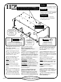
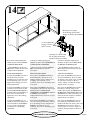
Consulte el diagrama ampliado para
identificar las piezas de las BISAGRAS y
las MÉNSULAS DE BISAGRA.
- Las PUERTAS pueden requerir de
ajustes. Siga las instrucciones abajo para
hacer los ajustes.
AJUSTE LAS PUERTAS:
Para ajustar las PUERTAS de un lado al
otro (horizontalmente), afloje el tornillo
de montaje varias vueltas y gire el tornillo
de ajuste hacia el interior o hacia el
exterior. Apriete el tornillo de montaje
después de hacer los ajustes.
Para ajustar las PUERTAS hacia arriba o
hacia abajo (vertical), afloje los dos
tornillos que aseguran las MÉNSULAS
DE BISAGRA al EXTREMO. Mueva las
PUERTAS hacia arriba o hacia abajo a la
ubicación deseada. Apriete los tornillos
después de hacer los ajustes.
Para ajustar las PUERTAS hacia atrás o
hacia adelante (profundidad), afloje el
tornillo de montaje una vuelta y mueva las
PUERTAS hacia el interior o hacia el
exterior según sea necesario. Apriete el
tornillo de montaje después de hacer los
ajustes.
Consulter le schéma agrandi pour
identifier les pièces des CHARNIÈRES et
CONSOLES DE CHARNIÈRE.
- Il faut peut--être ajuster les PORTES.
Suivre les indications ci--dessous
pour ajuster.
RÉGLAGES DE PORTES:
Pour ajuster les PORTES latéralement
(horizontalement), desserrer la vis de
montage quelques tours et tourner la vis
de réglage vers l’intérieur ou vers
l’extérieur. Serrer la vis de montage après
avoir ajusté.
Pour ajuster les PORTES de haut en bas
(verticalement), desserrer les deux vis qui
maintiennent les CONSOLES DE
CHARNIÈRE à l’EXTRÉMITÉ. Déplacer
les PORTES verticalement à
l’emplacement désiré. Serrer les vis après
avoir ajusté.
Pour ajuster les PORTES vers l’intérieur
où vers l’extérieur (profondeur), desserrer
la vis de montage un tour et déplacer les
PORTES vers l’intérieur ou vers
l’extérieur. Serrer la vis de montage après
avoir ajusté.
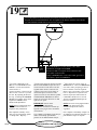
Refer to the enlarged diagram to
identify the parts on the HINGES
and HINGE BRACKETS.
- The DOORS may need some
adjustments. Follow the text below
to make needed adjustments.
DOOR ADJUSTMENTS:
To adjust the DOORS from side to
side (horizontal), loosen the
mounting screw several turns, then
turn the adjusting screw in or out.
Tighten the mounting screw after
making adjustments.
To adjust the DOORS up and down
(vertical), loosen both screws that
fasten the HINGE BRACKETS to
the END. Move the DOORS up or
down to the desired location.
Tighten the screws after making
adjustments.
To adjust the DOORS in or out
(depth), loosen the mounting screw
one turn and move the DOORS in
or out, as needed. Tighten the
mounting screw after making
adjustments.
Mounting screw (depth)
Vis de montage (profondeur)
Tornillo de montaje (profundidad)
Adjusting screw (horizontal)
Vis de réglage (horizontal)
Tornillo de ajuste (horizontal)
(vertical adjustment)
(réglage verticale)
(ajuste vertical)

15
409048
www.sauder. com/services
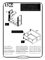
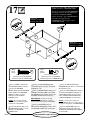
- Insert the DRAWER
SIDES (O and P) at an angle
into the slot at each end of the
DRAWER FRONT (M).
- Slide the DRAWER BACK (N)
into the grooves in the DRAWER
SIDES (O and P) until the edge of the
BACK is even with the SIDES.
* U.S. Patent No. 6,413,007
- Inserte los LADOS DE CAJÓN (O
y P) en ángulo dentro del encaje en cada
extremo de la CARA DE CAJÓN (M).
- Deslice el DORSO DE CAJÓN (N)
dentro de las ranuras de los LADOS DE
CAJÓN (O y P) hasta que el borde del
DORSO esté nivelado con los LADOS.
* No. de Patente EE.UU. 6,413,007
- Insérer les CÔTÉS DE TIROIR (O
et P) en biseau dans la fente dans chaque
extrémité du DEVANT DE TIROIR (M).
- Enfiler l’ARRIÈRE DE TIROIR (N)
dans les rainures des CÔTÉS DE
TIROIR (O et P) jusqu’à ce que le chant
de l’ARRIÈRE soit à fleur des CÔTÉS.
*BrevetÉtatUnisn_ 6.413.007
The tabs should insert freely into the slots. Gently tilt the
DRAWER SIDES side to side until the tabs slip into the slots.
Les pattes devraient s’insérer librement dans les fentes.
Légèrement incliner les CÔTÉS DE TIROIR d’un côté vers
l’autre jusqu’à ce que les pattes s’enfilent dans les fentes.
Las lengüetas deben insertarse sin problemas dentro de los
encajes. Ligeramente incline los LADOS DE CAJÓN de un lado
al otro hasta que las lengüetas se deslicen dentro de los encajes.
These edges should be even.
Ces chants devraient être à fleur.
Estos bordes deben estar nivelados.
Groove
Rainure
Ranura
2
nd
Groove
Rainure
Ranura
O
P
M
O
P
N
1
st
La page charge ...
La page charge ...
La page charge ...
La page charge ...
La page charge ...
La page charge ...
La page charge ...
La page charge ...
-
 1
1
-
 2
2
-
 3
3
-
 4
4
-
 5
5
-
 6
6
-
 7
7
-
 8
8
-
 9
9
-
 10
10
-
 11
11
-
 12
12
-
 13
13
-
 14
14
-
 15
15
-
 16
16
-
 17
17
-
 18
18
-
 19
19
-
 20
20
-
 21
21
-
 22
22
-
 23
23
-
 24
24
-
 25
25
-
 26
26
-
 27
27
-
 28
28


Sauder 409048 Assembly Instructions Manual
- Taper
- Assembly Instructions Manual
dans d''autres langues
- English: Sauder 409048
- español: Sauder 409048
Documents connexes
-
Sauder 101785 Assembly Instructions Manual
-
-
-
-
-
-
-
-
-
