Brizo T60P085-BN Guide d'installation
- Catégorie
- Articles sanitaires
- Taper
- Guide d'installation
Ce manuel convient également à

IMPORTANT DOCUMENTS ENCLOSED
CAUTION:
To reduce the risk of injury due to hot water
burns, make sure the enclosed labels are
applied where specified on the label.
DOCUMENTOS IMPORTANTES INCLUIDOS
AVISO:
Para reducir el riesgo de lesión por
quemaduras de agua caliente, asegúrese que
las etiquetas incluidas se han aplicado donde
se ha especificado en la etiqueta.
DOCUMENTS IMPORTANTS À L’INTÉRIEUR
MISE EN GARDE :
Pour réduire le risque d’ébouillantage, veuillez
apposer les étiquettes fournies aux endroits
indiqués sur celles-ci.

BY/POR/PAR _______________ COMPANY/COMPANIA/COMPAGNIE ________________
DATE/FECHA/LE ___________ PHONE/TELÉFONO/TELÉPHONE ____________________
TO BE FILLED OUT BY THE INSTALLER / PARA SER LLENADO POR EL INSTALADOR /
A REMPLIR PAR L’INSTALLATEUR:
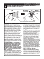
NOTICE TO INSTALLER: Place this label on the water heater
next to the temperature adjustment knob.
WARNING:
This series of tub/shower valves does not adjust automatically for
changes in temperature at the hot water heater or inlet. If the temperature
setting of the hot water heater or inlet is changed, the setting on these valves
must be adjusted manually! Failure to re-adjust the valve may result in hot
water burns or extreme cold resulting from variations in line pressure (such
as when a dishwasher or washing machine is in use while you are taking a
shower). After installation, verify that the temperature knob on the valve is set
so that changes in line pressure or temperature do not result in uncomfortable
water temperature changes. If the temperature setting of the hot water
heater or inlet is changed after installation of the valve, the setting of
the temperature knob also must be changed! Consult the installation
instruction sheet for instructions on how to make this setting, or call us at
1-877-345-BRIZO.
AVISO AL INSTALADOR: Coloque esta etiqueta en el calentador
de agua al lado de la perilla que ajusta la temperatura.
AVISO:
Esta serie de válvulas para bañeras/regaderas no se ajusta
automáticamente a los cambios de temperatura en el calentador de agua
o del agua de entrada. ¡Si el ajuste de temperatura del calentado del agua
caliente o del agua de entrada, el ajuste en estas válvulas debe ajustarse
manualmente! El no reajustar la válvula puede resultar en quemaduras por
agua caliente o temperaturas de agua extremadamente frías resultando en
variaciones de presión y temperatura (como cuando el fregador de platos
o la lavadora están funcionando mientras que se baña). Después de la
instalación, verifique que la perilla para el control de la temperatura en la
válvula está ajustada para que cambios de presión y de temperatura en
la línea no resulten en cambios de temperatura del agua incómodos. Si
el ajuste de la temperatura del calentador de agua o de la entrada de
agua se cambia después de la instalación de la válvula, la perilla que
ajuste ¡la temperatura también se debe cambiar! Consulte con su hoja de
instrucciones de instalación para saber como se ajusta o cambia el ajuste o
llámenos al 1-877-345-BRIZO.
AVIS À L’INSTALLATEUR : Placez cette étiquette sur le chauffe-
eau, près du bouton de réglage de température.
AVERTISSEMENT:
La soupape de robinet de baignoire ou de douche de cette série
ne se règle pas automatiquement en fonction des changements de
température de l’eau chaude au chauffe-eau ou de l’eau d’alimentation.
En cas de modification du réglage de température du chauffe-eau ou de
la température de l’eau d’alimentation, le réglage de ces soupapes doit
être modifié manuellement! Si le réglage de la soupape n’est pas modifié,
le robinet pourra permettre l’écoulement d’eau très chaude susceptible de
causer l’ébouillantage ou d’eau très froide, sous l’effet des variations de
pression et de température dans la tuyauterie d’alimentation (lorsque la
douche est utilisée en même temps que le lave-vaisselle ou la machine
à laver, par exemple). Après l’installation, assurez-vous que le bouton de
température sur la soupape est réglé de manière que les fluctuations de
pression et de température dans la tuyauterie d’alimentation n’entraînent
pas de changements de température de l’eau inconfortables. En cas
de modification du réglage de température du chauffe-eau ou de la
température de l’eau d’alimentation après l’installation de la soupape, le
réglage du bouton de température doit être modifié! Pour régler le bouton
de température, consultez la feuille d’instructions d’installation ou appelez-
nous au 1-877-345-BRIZO.
NOTICE TO INSTALLER: Place this label close to the valve where the
owner will see it, such as inside the door of a cabinet or vanity.
WARNING:
Water temperature changes due to seasonal or other inlet variations, such as changing
the setting on the hot water heater may require adjustment of the temperature knob
on your tub/shower valve to ensure a safe maximum temperature. This valve series
does not automatically adjust for inlet temperature changes. If changes occur and
you are not sure how to make the necessary temperature knob adjustments, please
consult the installation instruction sheet provided with this valve or call 1-877-345-
BRIZO. This valve is designed to reduce the risk of injury due to inlet pressure or
temperature changes, commonly caused by dishwashers, washing machines, toilets
and the like. It may not provide protection from hot water burns when there is
a failure of other temperature controlling devices elsewhere in the plumbing
system. After making the necessary adjustments please fill in the information below. This
valve/system has been set by the person listed below to help ensure a safe maximum
temperature. Any change in the setting may raise the temperature of the water coming
out of the shower or bath above the limit considered safe and could lead to hot water
burns. If this label has not been completed, you should verify that the temperature knob
has been properly adjusted to suit your individual installation. The installation instruction
sheet supplied with the valve provides information on how to make this setting.
AVISO AL INSTALADOR: Coloque esta etiqueta cerca de la válvula
donde el propietario la pueda ver, tal como dentro de la puerta del
gabinete o el tocador.
AVISO:
Los cambios de temperatura del agua por variaciones estacionales u otras variaciones en
el agua de entrada, como cambiando el ajuste en el calentador de agua pueden requerir el
ajuste de la perilla para el control de la temperatura de su unidad bañera/regadera para ayudar
a asegurar una temperatura máxima segura. Este
válvulas
no se ajusta automáticamente
a cambios de temperatura en el agua de admisión. Si los cambios ocurren y usted no está
seguro como hacer los ajustes necesarios con la perilla para controlar la temperatura, por favor
consulte la hoja de instrucciones de instalación proporcionada con esta válvula o llámenos al
1-877-345-BRIZO. Esta válvula está diseñada para reducir el riesgo de lesión por cambios de
temperatura del agua que entra o por los cambios de presión del agua que comúnmente son
causados por los usos simultáneos de fregadoras de platos, lavadoras, sanitarios y aparatos
similares. Pueda no proporcionar protección de quemaduras por el agua caliente cuando
hay una falla de otros mecanismos que controlan la temperatura del agua en otro sitio del
sistema de plomería. Después de hacer los ajustes necesarios, por favor escriba la información
a continuación. Esta válvula/sistema ha sido ajustada por la persona indicada a continuación para
ayudar a asegurar una temperatura máxima segura. Cualquier cambio al ajuste puede aumentar la
temperatura del agua que sale de la ducha o el baño sobre el límite considerado seguro y puede
resultar en quemaduras por el agua caliente. Si esta etiqueta no se a llenado, debe verificar si
la perilla para el control de la temperatura hay sido correctamente ajustada para al gusto de su
instalación individual. La hoja de instrucciones de instalación proporcionada con las válvulas le
suministra información sobre como hacer esto.
AVIS À L’INSTALLATEUR : Placez cette étiquette près de la soupape à
un endroit où le propriétaire pourra la voir, du côté intérieur de la porte
de l’armoire ou du meuble par exemple.
AVERTISSEMENT:
La température de l’eau peut varier en raison des changements de saison, d’une modification
du réglage du chauffe-eau ou d’autres changements. Par conséquent, un réglage du bouton
de température de votre soupape de douche ou de baignoire peut s’imposer pour que la
température maximale de l’eau demeure sécuritaire. Les soupapes de cette série ne s’ajustent pas
automatiquement aux changements de température de l’eau d’alimentation. Si des changements
vous obligent à régler le bouton de température et vous n’êtes pas certain de la marche à suivre,
veuillez consulter le feuillet d’instructions fourni avec la soupape ou appeler au 1-877-345-BRIZO.
Cette soupape est conçue pour réduire les risques de blessures causées par des changements de la
température ou de la pression de l’eau d’alimentation habituellement causés par le lave-vaisselle, la
machine à laver, une toilette ou un autre appareil qui consomme de l’eau. Elle peut ne pas assurer de
protection contre l’ébouillantage en cas de défectuosité d’un autre dispositif de régulation de
la température dans la tuyauterie. Après avoir effectué le réglage nécessaire, veuillez inscrire
l’information requise ci-dessous. La personne dont le nom figure ci-dessous a réglé cette soupape
pour qu’elle puisse maintenir une température maximale sécuritaire. Toute modification du réglage
peut entraîner une élévation de la température de l’eau s’écoulant par la douche ou dans la baignoire
au delà de la limite considérée sécuritaire, ce qui pourrait causer un ébouillantage. Si cette étiquette
n’a pas été remplie, vous devriez vous assurer que le bouton de température a été réglé en fonction
des caractéristiques de votre installation. Le feuillet d’instruction fourni avec la soupape indique la
marche à suivre pour effectuer le réglage.
T60 / T75 Series T66T Series
T60 / T75 Series T66T Series
T60P/T75P Series
T60P/T75P Series

102236 Rev. B
3
12/14/18 Rev. B
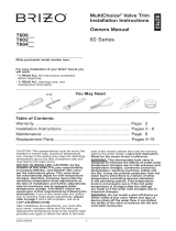
MultiChoice
®
Pressure
Balance Valve Trim
THIS VALVE MEETS OR EXCEEDS THE
FOLLOWING STANDARDS:
ASME A112.18.1/CSA B125.1 and ASSE 1016.
CAUTION: This system/device must be set by the
installer to ensure safe, maximum temperature.
Any change in the setting may raise the discharge
temperature above the limit considered safe and
may lead to hot water burns.
NOTICE TO INSTALLER: CAUTION!–As the
installer of this valve, it is your responsibility
to properly INSTALL and ADJUST this valve
per the instructions given. This valve does
not automatically adjust for inlet temperature
changes, therefore, someone must make the
necessary temperature knob adjustments at
the time of installation and further adjustments
may be necessary due to seasonal water
temperature change. YOU MUST inform the
owner/user of this requirement by following the
instructions. If you or the owner/user are unsure
how to properly make these adjustments, please
refer to pages 5 & 6 and if still uncertain, call us at
1-877-345-BRIZO (2749).
After installation and adjustment, you must ax
your name, company name and the date you
adjusted the temperature knob to the caution label
provided and apply or attach the label to the back
side of the closest cabinet door and the warning
label to the water heater. Leave this Instruction
Sheet for the owner’s/user’s reference.
WARNING: This thermostatic bath valve is
designed to minimize the eects of outlet water
temperature changes due to inlet pressure and
temperature changes, commonly caused by
dishwashers, washing machines, toilets and
the like. It may not provide protection from hot
water burns when there is a failure of other
temperature controlling devices elsewhere
in the plumbing system, if the temperature
knob is not properly set or if the hot water
temperature is changed after the settings
are made or if the water inlet changes due to
seasonal changes.
WARNING: Do not install a shut-o device on
either outlet of this valve. When this type of
device shuts o the water ow, it can defeat
the ability of the valve to balance the hot and
cold water pressures.
102236
www.brizo.com
1-877-345-BRIZO (2749)
?
Write purchased model number here.
T60P_______
Limited Warranty on Brizo
®
Faucets

102236 Rev. B
4
Parts and Finish. All parts (other than electronic parts and batteries) and finishes of this Brizo
®
faucet are warranted to the original consumer
purchaser to be free from defects in material and workmanship for as long as the original consumer purchaser owns the home in which the fau-
cet was first installed or, for commercial users, the warranty period is ten (10) years for multi-family residential (apartments and condominiums
and five (5) years for all other commercial uses, in each case from the date of purchase.
Electronic Parts and Batteries (if applicable). Electronic parts (other than batteries), if any, of this Brizo
®
faucet are warranted to the original
consumer purchaser to be free from defects in material and workmanship for five (5) years from the date of purchase or, for commercial users,
for one (1) year from the date of purchase. No warranty is provided on batteries.
What We Will Do. Brizo Kitchen & Bath Company will repair or replace, free of charge, during the applicable warranty period (as described
above), any part or finish that proves defective in material and/or workmanship under normal installation, use and service. If repair or replace-
ment is not practical, Brizo Kitchen & Bath Company may elect to refund the purchase price in exchange for the return of the product. These
are your exclusive remedies.
What Is Not Covered. Any labor charges incurred by the purchaser to repair, replace, install or remove this product are not covered by this
warranty. Brizo Kitchen & Bath Company shall not be liable for any damage to the product resulting from reasonable wear and tear, outdoor use,
misuse (including use of the product for an unintended application), freezing water, abuse, neglect or improper or incorrectly performed installa-
tion, maintenance or repair, including failure to follow the applicable care and cleaning instructions. Brizo Kitchen & Bath Company recommends
using a professional plumber for all installation and repair of faucets. We also recommend that you use only genuine Brizo
®
replacement parts.
What You Must Do To Obtain Warranty Service or Replacement Parts. A warranty claim may be made and replacement parts may be
obtained by calling 1-877-345-BRIZO (2749) or by contacting us by mail or online as follows (please include your model number and date of
purchase):
In the United States and Mexico: In Canada:
Brizo Kitchen & Bath Company Masco Canada Limited, Plumbing Group
Brizo Customer Solutions Technical Service Centre
55 E. 111th Street 350 South Edgeware Road
Indianapolis, IN 46280 St. Thomas, Ontario, Canada N5P 4L1
https://www.brizo.com/customer-support/contact-us https://www.brizo.com/customer-support/contact-us
Proof of purchase (original sales receipt) from the original purchaser must be made available to Brizo Kitchen & Bath Company for all war-
ranty claims unless the purchaser has registered the product with Brizo Kitchen & Bath Company. This warranty applies only to Brizo
®
faucets
installed in the United States of America, Canada and Mexico.
Limitation on Duration of Implied Warranties. TO THE EXTENT PERMITTED BY LAW, ANY IMPLIED WARRANTY, INCLUDING THE
IMPLIED WARRANTIES OF MERCHANTABILITY AND OF FITNESS FOR A PARTICULAR PURPOSE, IS LIMITED TO THE STATUTORY
PERIOD OR THE DURATION OF THIS WARRANTY, WHICHEVER IS SHORTER. Some states/provinces do not allow limitations on how
long an implied warranty lasts, so this limitation may not apply to you.
Limitation of Special, Incidental or Consequential Damages. BRIZO KITCHEN & BATH COMPANY SHALL NOT BE LIABLE FOR
ANY SPECIAL, INCIDENTAL OR CONSEQUENTIAL DAMAGES (INCLUDING LABOR CHARGES TO REPAIR, REPLACE, INSTALL
OR REMOVE THIS PRODUCT), WHETHER ARISING OUT OF BREACH OF ANY EXPRESS OR IMPLIED WARRANTY, BREACH OF
CONTRACT, TORT, OR OTHERWISE. BRIZO KITCHEN & BATH COMPANY SHALL NOT BE LIABLE FOR ANY DAMAGE TO THE
FAUCET RESULTING FROM REASONABLE WEAR AND TEAR, OUTDOOR USE, MISUSE (INCLUDING USE OF THE PRODUCT
FOR AN UNINTENDED APPLICATION, FREEZING WATER, ABUSE, NEGLECT OR IMPROPER OR INCORRECTLY PERFORMED
INSTALLATION, MAINTENANCE OR REPAIR, INCLUDING FAILURE TO FOLLOW THE APPLICABLE INSTALLATION, CARE AND
CLEANING INSTRUCTIONS. Some states/provinces do not allow the exclusion or limitation of special, incidental or consequential damages,
so the above limitations and exclusions may not apply to you. Notice to residents of the State of New Jersey: The provisions of this warranty,
including its limitations, are intended to apply to the fullest extent permitted by the laws of the State of New Jersey.
Additional Rights. This warranty gives you special legal rights, and you may also have other rights which vary from state/province to state/
province.This is Brizo Kitchen & Bath Company’s exclusive written warranty and the warranty is not transferable.
If you have any questions or concerns regarding our warranty, please contact us as provided above or visit our website at www.brizo.com.
Limited Warranty on Brizo
®
Faucets
© 2019 Masco Corporation of Indiana

102236 Rev. B
5
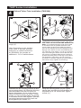
T60P Series Installation
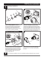
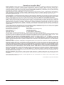
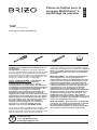
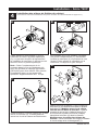
1
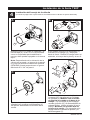
Cartridge Installation
A.
C.
Turn o water supplies. Remove
cover (1), bonnet nut (2) and test cap (3)
from the body. If this is not a thin wall
mounting, the entire plasterguard (4)
may be removed. If screen (5) is in place,
remove before installing cartridge.
For back to back or reverse installations
(hot on right and cold on left) insert the
cartridge with the “hot side” on the right.
If you are not making a reverse or back
to back installation skip this step and
continue with step 1C.
Slide bonnet nut (1) over the cartridge
and thread onto the body. Hand tighten
securely.
B.
Rotate the cartridge (1) so the words
“hot side” (2) appear on the left. Insert
cartridge into valve body as shown. Make
sure the cartridge tubes and O-rings (3) are
properly seated in holes at the base of the
body. Ensure the keys on the body are fully
engaged with the slots in the body (4).
Back to back Installation
Normal Installation (changes not required)
Reverse
Installation
Cold
Hot
1
2
3
1
4
3
1
5
4
2
For Tub Spout installation refer to the installation guide provided with your tub spout.

102236 Rev. B
6
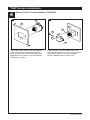
T60P Series Installation
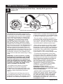
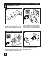
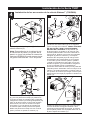
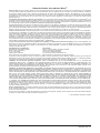
3
Adjusting the Rotational Limit Stop – Identify RLS type from
pages 4-5.
IMPORTANT:
The Rotational Limit Stop is used to limit
the amount of hot water available such that,
if set properly, the user will not be scalded
if the handle accidentally is rotated all the
way to “hot” when a person is showering
or lling a tub. The rst position allows
the LEAST amount of hot water to mix
with the cold water in the system. In the
rst position the water will be the coldest
possible when the handle is turned all the
way to hot. As you move the Rotational Limit
Stop counterclockwise, you progressively
add more and more hot water in the mix.
The last position to the left will result in the
greatest amount of hot water to the mix, and
the greatest risk of scald injury if someone
accidentally turns the valve handle all the
way to the hot side while showering or lling
a tub.
WARNING: In some instances, setting
the Rotational Limit Stop in the hottest
position (full counterclockwise) could
result in scald injury. It is necessary to
adjust the Rotational Limit Stop so that
the water coming out of the valve will not
scald the user when the handle of the
valve is rotated to the hot side.
• According to the majority of industry
standards, the maximum allowable
temperature of the water exiting the valve
is 120°F (Your local plumbing codes may
require a water temperature less than
120°F).
• The Rotational Limit Stop may need to
be readjusted seasonally if the inlet water
temperature changes. For example, during
the winter, the cold water temperature is
colder than it is during the summer which
could result in varying outlet temperatures.
A water temperature for a comfortable bath
or shower is typically between 90°F - 110°F.
• Run the water so that the cold water is
as cold as it will get and hot water is as hot
as it will get. Place the handle on the stem
(see page 7, step 4D) and rotate the handle
counterclockwise until the handle stops.
• Place a thermometer in a plastic tumbler
and hold in the water stream. If the water
temperature is above 120°F, the Rotational
Limit Stop must be repositioned clockwise
to decrease valve outlet water temperature
to be less than 120°F or to meet the
requirements of your local plumbing codes.
• To adjust the temperature of the water
coming out of the valve, pull the disc back
to a position where it is possible to remove
the Rotational Limit Stop and readjust the
teeth engagement position to the desired
temperature. Clockwise will decrease
the outlet temperature, counterclockwise
will increase the outlet temperature.
Temperature change per tooth (notch)
could be 4° - 16°F based on inlet water
conditions. Repeat as necessary.
Push disc until fully seated.
WARNING: Failure to re-install Disc
after setting Rotational Limit Stop could
result in scald injury.
• MAKE SURE COLD WATER FLOWS
FROM THE VALVE FIRST. MAKE SURE
WATER FLOWING FROM THE VALVE
AT THE HOTTEST FLOW POSSIBLE
DOES NOT EXCEED 120°F OR THE
MAXIMUM ALLOWED BY YOUR LOCAL
PLUMBING CODE.
1st Position
Hotter
RLS with removable disc
Stem
Disc

102236 Rev. B
7
T60P Series Installation
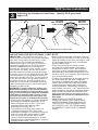
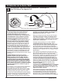
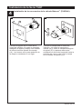
ADJUSTING THE ROTATIONAL LIMIT STOP
IMPORTANT: The Rotational Limit Stop is
used to limit the amount of hot water available
such that, if set properly, a scald injury is less
likely to occur if the handle accidentally is
rotated all the way to “hot” when a person is
showering or lling a tub. The rst position
allows the LEAST amount of hot water to
mix with the cold water in the system. In the
rst position the water will be the coldest
possible when the handle is turned all the way
to hot. As you move the Rotational Limit Stop
counterclockwise, you progressively add more
and more hot water in the mix. The last position
to the left will result in the greatest amount of
hot water to the mix, and the greatest risk of
scald injury if someone accidentally turns the
valve handle all the way to the hot side while
showering or lling a tub.
WARNING: In some instances, setting the
Rotational Limit Stop in the hottest position
(full counterclockwise) could result in scald
injury. It is necessary to adjust the Rotational
Limit Stop so that the water coming out of
the valve will not scald the user when the
handle of the valve is rotated to the hot side.
• According to the majority of industry standards,
the maximum allowable temperature of the
water exiting the valve is 120°F (Your local
plumbing codes may require a water
temperature less than 120°F).
• The Rotational Limit Stop may need to be
re-adjusted seasonally if the inlet water
temperature changes. For example, during the
winter, the cold water temperature is colder
than it is during the summer which could
result in varying outlet temperatures. A water
temperature for a comfortable bath or shower is
typically between 90°F - 110°F.
• Run the water so that the cold water is as cold
as it will get and hot water is as hot as it will get.
Place the handle on the stem (see page 9, step
4F) and rotate the handle coun- terclockwise
until the handle stops.
• Place a thermometer in a plastic tumbler
and hold in the water stream. If the water
temperature is above 120°F, the Rotational
Limit Stop must be repositioned clockwise to
decrease valve outlet water temperature to be
less than 120°F or to meet the requirements of
your local plumbing codes.
• To adjust the temperature of the water coming
out of the valve, pull the white Rotational
Limit Stop (1) outward and rotate. Clockwise
rotation will decrease the outlet temperature,
counterclockwise rotation will increase the
outlet temperature. Temperature change per
tooth (notch) could be 4° - 16°F based on inlet
water conditions. Repeat as necessary. When
finished, make sure that the Rotational Limit
Stop is fully retracted into the seated position.
WARNING: Do not take the Rotational Limit
Stop apart.
• MAKE SURE COLD WATER FLOWS
FROM THE VALVE FIRST. MAKE SURE
WATER FLOWING FROM THE VALVE AT
THE HOTTEST FLOW POSSIBLE DOES
NOT EXCEED 120°F OR THE MAXIMUM
ALLOWED BY YOUR LOCAL PLUMBING
CODE.
1
1
HOTTER
MÁS CALIENTE
PLUS CHAUD
COLDER
MÁS FRÍA
PLUS FROID
RLS with pull/turn adjustment
3
Adjusting the Rotational Limit Stop – Identify RLS type from
pages 4-5.

102236 Rev. B
8
T60P Series Installation
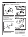
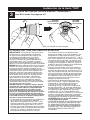
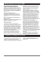
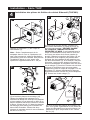
Valve Trim Installation
(See page 8 & 9 for Siderna® valve trim installation.)
4
C.
D.
A.
B.
Slide O-ring (1) over cartridge and the
bonnet nut (2). The O-ring, which acts as
a spacer to steady the sleeve, should rest
behind the bonnet nut.
Note: Depending on the location of the
valve in the wall and wall thickness,
an optional extension kit (RP81665)
can provide an additional 1 3/4” of wall
thickness.
If your model requires a spacer (1), insert
it into the sleeve (2) and push it to the
front. Slide the sleeve over the cartridge,
body and O-ring.
Secure the escutcheon (1) to the bracket
(2) using the 2 screws provided (3). Do not
overtighten escutcheon screws.
Slide trim ring (1) over trim sleeve (2) and
insert into escutcheon (3). Models with
side set screw in handle base - Secure
handle (4) onto the stem using screw (5)
and a phillips head screwdriver. Insert
button (6)into handle. Models with axial
screw in handle blade - Secure handle
onto the stem using set screw and hex
wrench (7).
1
2
1
2
1
1
2
3
1
1
2
2
3
4
5
7
6

102236 Rev. B
9
T60P Series Installation
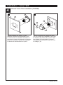
Siderna
®
Valve Trim Installation (T60P080)
4
Assemble the two mounting sleeves (9) and
two mounting plates (10). Slide the mounting
plate assemblies over the trim sleeve so
that the tabs/plates (10) are at the top and
bottom of the trim sleeve, as shown. Thread
screws (11) into mounting plates just enough
to assemble the two sides together. Slide the
mounting plates back against the wall and
nish tightening the screws (11).
Using the mounting plates (10) as a guide,
enlarge hole around rough so that plates can
be pushed up to 1/8" into the wall. Tighten
screws (11).
Using supplied Hex wrench, install both anti-
rotational pins (3) into holes (4) in the valve body.
USE CARE TO NOT DROP PINS BEHIND THE
WALL. It is important that the rough be mounted
in the wall as level as possible because of the
square shape of this product. Slide trim sleeve
(5) over the cartridge and bonnet aligning the two
legs (6) of the sleeve over the anti-rotational pins
(3). If the trim is not square, you can try removing
a pin and holding the sleeve secure with the two
set screws (7) provided. Make sure the sleeve is
pushed all the way back so the legs of the sleeve
rest against the valve body. The set screws (7)
should be in a position where they hit just behind
the bonnet nut (8). Tighten set screws (7).
Remove plaster guard (1) from
rough (2).
Note: Depending on the location
of the valve in the wall and wall
thickness, an optional extension
kit (RP92056) can provide an
additional 1 3/4” of wall thickness.
A.
1
2
B.
7
6
7
43
5
8
C.
9
9
11
10
10
11
D.
1/8"
(3 mm)
10
11
10
11
3
4

102236 Rev. B
10
T60P Series Installation
F.
Place the center hole of the escutcheon
(12) over the trim sleeve and carefully
push it back to the mounting plates (10).
Magnets on the back of the escutcheon
will keep it in place.
Place handle (13) over valve stem (14)
and onto the trim sleeve (5). Lever should
point horizontally to 3 o’clock position.
Secure handle with set screw (15).
4
Siderna
®
Valve Trim Installation (T60P080)
13
14
E.
10
12
15
5

102236 Rev. B
11
T60P Series Maintenance
Faucet leaks from tub spout/showerhead:
SHUT OFF WATER SUPPLIES.
Replace seats and springs–Repair
Kit RP4993. Check condition of lower O-rings
and replace if necessary RP14414. See
Helpful Hints 1, 2, & 3.
If leak persists:
SHUT OFF WATER SUPPLIES.
Replace valve cartridge RP46074.
See Helpful Hints 1, 2, 3 & 5.
Unable to maintain constant
water temperature:
Replace valve cartridge RP46074 or follow
instructions in Helpful Hints 1, 2, 4 & 5.
Helpful Hints:
1. Before removing valve cartridge assembly
for any maintenance, be sure to note the
position of the rotational limit stop on the cap.
The valve cartridge assembly must always be
put back in the same position. BE SAFE! After
you have nished the installation, turn on
valve to make sure COLD WATER FLOWS
FIRST.
2. To remove valve cartridge from body, shut
o water supplies and remove handle and
bonnet nut. Do not pry the valve cartridge
out of the body with a screwdriver. Place
handle on stem and rotate counterclockwise
approximately 1/4 turn after the stop has
been contacted. Lift valve cartridge out of
body.
3. To remove seats and springs, remove
valve cartridge. Separate cap assembly
from the housing assembly by rotating
the cap assembly counterclockwise 90
o
(degrees). Separate cap and housing
assemblies. Remove seats and springs and
replace. Place the largest diameter of the
spring into the seat pocket rst and then
press the tapered end of the seal over the
spring. Reassemble valve cartridge and
replace in body following instructions given
in 1 above.
4. If the water in your area has lime, rust,
sand or other contaminants in it, your
pressure balance valve will require periodic
inspection. The frequency of the inspection
will depend on the amount of contaminants
in the water. To inspect valve cartridge
remove it and follow the steps in note 1
above. Turn the valve to the full mix position
and shake the cartridge vigorously. If there
is a rattling sound, the unit is functional and
can be reinstalled following instructions
given in note 1 above. If there is no rattle,
replace valve cartridge RP46074.
5. Make sure the rotational limit stop is fully
seated and retained. Use disc, if included.
Cleaning and Care
Care should be given to the cleaning
of this product. Although its nish is
extremely durable, it can be damaged by
harsh abrasives or polish. To clean, simply
wipe gently with a damp cloth and blot dry
with a soft towel.

102236 Rev. B
12

102236 Rev. B
13
ESTA VÁLVULA CUMPLE O EXCEDE LAS
SIGUIENTES NORMAS:
ASME A112.18 1 / CSA B125.1 y ASSE 1016.
ADVERTENCIA: El instalador debe apostar
este systema/divisa para garantizar temperatura
maximo y seguro. Cualqueir cambio en el ajuste
puede subir la temperatura del agua de descarga
sobre el límite considerado seguro y puede resultar
en quemaduras de agua caliente.
AVISO PARA EL INSTALADOR: PRECAUCIÓN
– Como instalador de esta válvula, es su
responsabilidad de INSTALAR Y AJUSTAR
apropiadamente esta válvula como se describe
en las instrucciones, por lo tanto, debe
haber una persona para hacer los ajustes
necesarios del pomo para la temperatura
en el momento que se haga la instalación
y pueda necesitar ajustes adicionales por
los cambios estacionales de la temperatura
del agua. USTED DEBE informarle al dueño/
usuario sobre este requisito siguiendo las
instrucciones. Si usted o el dueño/usuario
no están seguros como hacer estos ajustes
apropiadamente, por favor reérase al Páginas
5 & 6 y si todavía no está seguro, llámenos al
1-877-345-BRIZO (2749).
Después de hacer la instalación y el ajuste,
usted puede agregarle a la etiqueta de aviso
proporcionada, su nombre, el nombre de la
compañía y la fecha cuando ajustó y el pomo para
la temperatura y aplicar o jar la etiqueta al dorso
de la puerta del gabinete más cercano y la etiqueta
de aviso al calentador de agua. Deje la Hoja de
Instrucciones para referencia del dueño/usuario.
ADVERTENCIA: Esta válvula termostática está
diseñada para minimizar los efectos de los
cambios de temperatura de agua por causa
de los cambios de presión y de temperatura
en el agua de entrada, comúnmente causados
por lavadoras de platos, lavadoras de ropa,
inodoros, y otros aparatos por el estilo. Puede
no proporcionar protección de quemaduras de
agua caliente cuando hay alguna falla de otros
aparatos para el control de temperatura en otro
sitio en el sistema de plomería. También no
proporcionará protección si el pomo para el
ajuste de la temperatura no está apropiadamente
jo o si cambia la temperatura del agua caliente
después de hacer los ajustes o si los cambios
del agua de entrada son por los cambios
estacionales.
ADVERTENCIA: No instale un aparato de corte
o cierre en cualquiera de las tomas de esta
válvula. Cuando este tipo de aparato cierra el
ujo de agua, puede hacer fallar la habilidad de
la válvula de balancear las presiones del agua
caliente y fría.
www.brizo.com
1-877-345-BRIZO (2749)
?
12/14/18 Rev. B
Accesorios de la válvula
de presión balanceada
MultiChoice
®
102236
Escriba aquí el número del modelo comprado.
T60P_______

102236 Rev. B
14
Piezas y Acabado. Todas las piezas (excepto los componentes electrónicos y las pilas) y acabados de esta llave de agua/grifo Brizo
®
están garantizados al consumidor comprador original de estar libres de defectos en material y fabricación durante el tiempo que el
comprador original sea propietario de la vivienda en la que la llave de agua fue originalmente instalada o, para usuarios comerciales,
el período de garantía es de diez (10) años para viviendas multifamiliares (apartamentos y condominios y cinco (5) años para todos
los demás usos comerciales, en cada caso desde la fecha de compra.
Piezas electrónicas y pilas (si aplicable). Las piezas electrónicas (excepto las pilas), si las hay, de esta llave de agua/grifo Brizo
®
están garantizadas al consumidor comprador original de estar libres de defectos en material y fabricación durante cinco (5) años a
partir de la fecha de compra en el caso de los consumidores comerciales, durante un (1) año a partir de la fecha de compra.
No ofrecemos garantía en la pilas.
Lo que haremos. La compañía Brizo Kitchen & Bath Company reparará o reemplazará, sin costo alguno, durante el periodo de
garantía aplicable (como descrito arriba) cualquier pieza o acabado que demuestre estar defectuosa en material y/o mano de obra
bajo la instalación, el uso y el servicio normal. Si la reparación o el reemplazo no es práctico, Brizo Kitchen & Bath Company puede
optar por reembolsarle el precio de compra a cambio de la devolución del producto. Estos son sus remedios exclusivos.
Lo que no está cubierto. Esta garantía no cubre los costos de mano de obra incurridos por el comprador para reparar, reemplazar,
instalar o desmontar este producto. Brizo Kitchen & Bath Company no será
́
responsable por cualquier daño al grifo que resulte del
desgaste razonable, uso en el exterior de la propiedad, uso indebido (incluyendo el uso del producto para una aplicación indebida),
agua helada, abuso, negligencia, o instalación, mantenimiento o reparación realizadas incorrectamente, incluyendo el no seguir las
instrucciones correspondientes para el cuidado, la limpieza y el mantenimiento. Brizo Kitchen & Bath Company recomienda que
un plomero profesional haga toda la instalación y las reparaciones. También recomendamos que use solo piezas de repuestos
originales Brizo
®
.
Lo que usted debe hacer para obtener servicio de garantía o piezas de repuesto. Puede hacer un reclamo para la garantía
y puede obtener piezas de repuesto llamando al 1-877-345-BRIZO (2749) o contactándonos por correo o en línea de la siguiente
manera (por favor incluya su número de modelo y fecha de compra):
En los Estados Unidos y México: En Canadá:
Brizo Kitchen & Bath Company Masco Canada Limited, Plumbing Group
Brizo Customer Solutions Technical Service Centre
55 E. 111th Street 350 South Edgeware Road
Indianapolis, IN 46280 St. Thomas, Ontario, Canada N5P 4L1
https://www.brizo.com/customer-support/contact-us https://www.brizo.com/customer-support/contact-us
El comprobante de compra (recibo de venta original) del comprador original debe estar disponible a Brizo Kitchen & Bath Company
para todos los reclamos de garantía a menos que el comprador haya registrado el producto con Brizo Kitchen & Bath Company. Esta
garantía se aplica solo a las llaves de agua Brizo
®
instaladas en los Estados Unidos de América, Canadá y México.
La limitación de la duración de las garantías implícitas. HASTA EL ALCANCE EN QUE LA LEY LO PERMITA, CUALQUIER
GARANTÍA IMPLÍCITA, INCLUIDAS LAS GARANTÍAS IMPLÍCITAS DE COMERCIABILIDAD Y DE IDONEIDAD PARA UN
PROPÓSITO PARTICULAR, ESTÁ LIMITADA AL PERÍODO LEGAL O A LA DURACIÓN DE ESTA GARANTÍA, LO QUE SEA MÁS
CORTO. Algunos estados/provincias no permiten la limitación de la duración de una garantía implícita por lo que esta limitación
puede no aplicarle.
Limitación de daños especiales, incidentales o consiguientes. BRIZO KITCHEN & BATH COMPANY NO SERÁ RESPONSABLE
POR NINGÚN DAÑO ESPECIAL, INCIDENTAL O CONSIGUIENTE (INCLUYENDO LOS GASTOS DE MANO DE OBRA PARA
REPARAR, REEMPLAZAR, INSTALAR O DESMONTAR ESTE PRODUCTO), YA SEA RESULTADO DEL INCUMPLIMIENTO DE
CUALQUIER GARANTÍA EXPRESA O IMPLÍCITA, INCUMPLIMIENTO DE CONTRATO, AGRAVIO O DE OTRA MANERA. BRIZO
KITCHEN & BATH COMPANY NO SE RESPONSABILIZARÁ POR CUALQUIER DAÑO AL GRIFO QUE RESULTE DEL DESGASTE
RAZONABLE, USO EN EL EXTERIOR DE LA PROPIEDAD, USO INDEBIDO (INCLUYENDO EL USO DEL PRODUCTO PARA
UNA APLICACIÓN NO INTENCIONADA), AGUA HELADA, ABUSO, NEGLIGENCIA O INSTALACIÓN, MANTENIMIENTO O
REPARACIÓN INADECUADA O INCORRECTA, INCLUYENDO EL NO SEGUIR LAS INSTRUCCIONES CORRESPONDIENTES
PARA LA INSTALACIÓN, EL CUIDADO, Y LA LIMPIEZA. Algunos estados/provincias no permiten la exclusión o limitación de daños
especiales, incidentales o consecuentes, por lo que estas limitaciones y exclusiones puedan no aplicarle. Aviso para los residentes
del estado de New Jersey: Las disposiciones de este documento tienen la intención de aplicarse en la máxima medida permitida por
las leyes del estado de New Jersey.
Derechos adicionales. Esta garantía le otorga derechos legales específicos, y también puede tener otros derechos que varían
de estado/provincia a estado/provincia. Esta es la garantía escrita exclusiva de Brizo Kitchen & Bath Company y la garantía no es
transferible.
Si tiene preguntas o dudas con respecto a nuestra garantía, por favor comuníquese con nosotros como se indica arriba o visite
nuestro sitio web www.brizo.com.
Garantía en los grifos Brizo
®
© 2019 Masco Corporación de Indiana

102236 Rev. B
15
Instalación de la Serie T60P
1
Instalación del Cartucho
A.
C.
Cierre los suministros de agua. Quite la
cubierta (1), la tuerca tapa (2) y la tapa de
prueba (3). Si no es para instalar en pared
delgada, puede quitar el protector (4) de
yeso completo. Si la pantalla (5) está en
lugar, quite antes de instalar el cartucho.
En las instalaciones dorso con dorso o al
reverso (caliente en la derecha y fría en
la izquierda) introduzca el cartucho con la
inscripción “hot side” a la derecha. Si usted
no está instalando al reverso o dorso con
dorso omita este paso y continúe con el
paso 1C.
Deslice la tuerca tapa (1) sobre el
cartucho
y enrosque en el cuerpo de la válvula.
Apriete a mano bien.
B.
Gire el cartucho (1) de manera que las palabras
‘hot side’ (lado caliente) (2) aparezcan a la
izquierda. Introduzca el cartucho en la válvula
como se muestra. Asegúrese que los tubos del
cartucho y los aros-O (3) estén apropiadamente
sentados en los agujeros en la base del cuerpo de
la válvula. Asegúrese que la parte dentada en el
cuerpo de la pieza encaje completamente en las
muescas de éste (4).
Instalación de Espalda a Espalda
Instalación Normal (No serequerá cambios)
Instalación
Invertido
Fría
Caliente
1
2
3
1
4
3
1
5
4
2
Para la instalación del surtidor para la bañera vea la guía de instalación proporcionada
con su surtidor.

102236 Rev. B
16
Instalación de la Serie T60P
3
El Ajuste del Tope que Limita la Rotación – Identique el
tipo RLS desde las páginas 4-5.
IMPORTANTE:
El Ajuste del Tope que Limita la Rotación
se usa para limitar la cantidad de agua
caliente disponible de manera que, si
ajustado apropiadamente, el usuario no se
quemará si la manija se gira accidentalmente
completamente a “hot” (“caliente”) cuando
una persona se está duchando o llenando
la bañera. La primera posición permite la
cantidad MÍNIMA de agua caliente mixta con
la fría en el sistema. En la primera posición
el agua estará lo más fría posible cuando
la manija se gira completamente a caliente.
Mientras que mueve el Ajuste del Tope que
Limita la Rotación en dirección contrario a
las manecillas del reloj, progresivamente
aumentará el agua caliente en la mezcla más
y más. La última posición a la izquierda es
la de mayor cantidad de agua caliente en la
mezcla, y tiene el mayor riesgo de lesión por
quemadura si alguien accidentalmente abre
la manija de la válvula completamente a la
posición caliente mientras que se baña o llena
la bañera.
ADVERTENCIA: En algunos casos,
ajustar el Ajuste del Tope que Limita la
Rotación en la posición más caliente
(completamente en el sentido contrario
a la dirección de las manecillas del reloj)
puede resultar en lesión por quemadura.
Es necesario ajustar el Tope que Limita la
Rotación de manera que el agua que sale
de la válvula no queme o escalde al usuario
cuando la manija de la válvula se gira al
lado caliente.
De acuerdo con la mayoría de los estándares
de la industria, la temperatura máxima
permisible del agua que sale es 120°F (Sus
códigos locales de plomería pueden requerir
una temperatura de agua menor de 120°F).
El Tope que Limita la Rotación puede requerir
el ajuste estacional si la temperatura del agua
cambia. Por ejemplo, durante el invierno,
la temperatura del agua fría es más fría que
durante el verano resultando en temperaturas
variadas en el agua de salida. Una temperatura
de agua para un baño o ducha confortable
típicamente es entre 90°F - 110°F.
Deje que el agua corra de manera que el agua
fría esté lo más fría posible y la caliente esté lo
más caliente posible. Coloque la manija en la
espiga (vea la página 7, paso 4D) y gire la manija
en dirección contraria a las manecillas del reloj
hasta que la manija pare.
Coloque el termómetro en un vaso plástico
y sosténgalo bajo el chorro de agua. Si la
temperatura de agua está por encima de 120°F
el tope que limita la rotación debe ajustarse otra
vez moviéndolo en sentido de las manecillas
del reloj para reducir la temperatura del agua de
salida de la válvula a menos de 120°F o para que
cumpla con los requisitos de sus códigos locales
de plomería.
Para ajustar la temperatura del agua que sale
de la válvula, hale el disco otra vez a la posición
donde se puede remover el Tope del Límite
Rotacional y reajuste el engranaje de los dientes
a la posición para la temperatura deseada. Al
mover en dirección de las manecillas del reloj
reducirá la temperatura del agua de salida, y al
contrario aumentará la temperatura del agua de
salida. El cambio de temperatura por cada diente
(muesca) puede ser de 4°F-16°F dependiendo
de la condición del agua de entrada. Si es
necesario repítalo.
Presione el disco hasta que está asentado
completamente. ADVERTENCIA: Si no reinstala
el Disco después de hacer el ajuste del Tope
del Límite Rotacional pudiera escaldarse con
agua demasiado caliente.
ASEGÚRESE QUE EL AGUA FRÍA FLUYA DE
LA VÁLVULA PRIMERO. ASEGÚRESE QUE
EL AGUA QUE FLUYE DE LA VÁLVULA EN
LA POSICIÓN MÁS CALIENTE POSIBLE NO
EXCEDA 120°F O EL MÁXIMO PERMITIDO
POR SUS CÓDIGOS LOCALES DE PLOMERÍA.
Posición Primera
Más
Caliente
Unidad
del Vástago
RLS con disco desmontable.
Disco

102236 Rev. B
17
Instalación de la Serie T60P
3
El Ajuste del Tope que Limita la Rotación – Identique el
tipo RLS desde las páginas 4-5.
EL AJUSTE DEL TOPE QUE LIMITA LA ROTACIÓN:
IMPORTANTE: El Ajuste del Tope que Limita
la Rotación se usa para limitar la cantidad
de agua caliente disponible de manera que,
si ajustado apropiadamente, Una lesión
de escaldado es menos probable que se
ocurra si la manija se gira accidentalmente
completamente a “hot” (“caliente”) cuando
una persona se está duchando o llenando la
bañera. La primera posición permite la cantidad
MÍNIMA de agua caliente mixta con la fría en el
sistema. En la primera posición el agua estará
lo más fría posible cuando la manija se gira
completamente a caliente. Mientras que mueve
el Ajuste del Tope que Limita la Rotación en
dirección contrario a las manecillas del reloj,
progresivamente aumentará el agua caliente
en la mezcla más y más. La última posición
a la izquierda es la de mayor cantidad de
agua caliente en la mezcla, y tiene el mayor
riesgo de lesión por quemadura si alguien
accidentalmente abre la manija de la válvula
completamente a la posición caliente mientras
que se baña o llena la bañera.
ADVERTENCIA: En algunos casos, ajustar
el Ajuste del Tope que Limita la Rotación en
la posición más caliente (completamente
en el sentido contrario a la dirección de
las manecillas del reloj) puede resultar en
lesión por quemadura. Es necesario ajustar
el Tope que Limita la Rotación de manera
que el agua que sale de la válvula no queme
o escalde al usuario cuando la manija de la
válvula se gira al lado caliente.
• De acuerdo con la mayoría de los estándares
de la industria, la temperatura máxima
permisible del agua que sale es 120°F (Sus
códigos locales de plomería pueden requerir
una temperatura de agua menor de 120°F).
• El Tope que Limita la Rotación puede requerir
el ajuste estacional si la temperatura del agua
cambia. Por ejemplo, durante el invierno,
la temperatura del agua fría es más fría
que durante el verano resultando en tem-
peraturas variadas en el agua de salida. Una
temperatura de agua para un baño o ducha
confortable típicamente es entre 90°F - 110°F.
• Deje que el agua corra de manera que el agua
fría esté lo más fría posible y la caliente esté
lo más caliente posible. Coloque la manija en
la espiga (vea la página 9, paso 4F) y gire la
manija en dirección contraria a las manecillas
del reloj hasta que la manija pare.
• Coloque el termómetro en un vaso plástico y
sosténgalo bajo el chorro de agua. Si la tem-
peratura de agua está por encima de 120°F el
tope que limita la rotación debe ajustarse otra
vez moviéndolo en sentido de las manecillas
del reloj para reducir la temperatura del agua
de salida de la válvula a menos de 120°F o
para que cumpla con los requisitos de sus
códigos locales de plomería.
• Para ajustar la temperatura del agua que
sale de la válvula, Tirar la Parada de Límite
Rotacional de color blanco hacia afuera
y girarla. Al mover en dirección de las
manecillas del reloj reducirá la temperatura
del agua de salida, y al contrario aumentará
la temperatura del agua de salida. El cambio
de temperatura por cada diente (muesca)
puede ser de 4°F-16°F dependiendo de la
condición del agua de entrada. Si es necesario
repítalo. Cuando haya terminado, asegúrese
de que la Parada de Límite Rotacional esté
completamente retraída a la posición sentada.
ADVERTENCIA: No tome la Parada de
Límite Rotacional aparte.
• ASEGÚRESE QUE EL AGUA FRÍA FLUYA DE
LA VÁLVULA PRIMERO. ASEGÚRESE QUE
EL AGUA QUE FLUYE DE LA VÁLVULA EN
LA POSICIÓN MÁS CALIENTE POSIBLE NO
EXCEDA 120°F O EL MÁXIMO PERMITIDO
POR SUS CÓDIGOS LOCALES DE
PLOMERÍA.
1
1
HOTTER
MÁS CALIENTE
PLUS CHAUD
COLDER
MÁS FRÍA
PLUS FROID
RLS con ajuste de tracción/giro.

102236 Rev. B
18
Instalación de la Serie T60P
4
Instalación del herraje de la válvula
(Consulte la página 8 & 9 para obtener la instalación de la válvula de ajuste Siderna®)
A.
B.
Deslice el aro O (1) sobre el cartucho y la
tuerca tapa (2). El aro O, el cual funciona
como un separador para estabilizar la
manga, debe quedar apoyado en la tuerca
tapa.
Nota: Dependiendo de la ubicación de la
válvula en la pared y el grosor de la pared,
un juego de piezas de extensión opcional
(RP81665) puede proporcionar un grosor
adicional de 1 3/4” de pared.
Si su modelo requiere un separador (1),
insértelo en la manga (2) y empújelo
hacia el frente. Deslice la manga sobre el
cartucho, el cuerpo de la pieza y el aro O.
Fije la roseta con oricio (1) al soporte (2)
usando los 2 tornillos suministrados (3).
No apriete demasiado los tornillos de la
roseta.
1
2
1
2
1
C.
D.
Deslice la argolla de accesorio (1) sobre
la manga (2) e introdúzcalo en la chapa
de cubierta (3). Modelos con el tornillo
de jación al costado en la base de la
manija – Fije la manija (4) en la espiga
usando el tornillo (5) y el destornillador de
cabeza Philips. Inserte el botón (6) en la
manija. Modelos con tornillo axial en
la hoja de la manija - Fije la manija en la
espiga usando el tornillo de jación y la
llave hexagonal (7).
1
2
3
1
1
2
2
3
4
5
7
6

102236 Rev. B
19
C.
9
9
11
10
10
11
Instalación de la Serie T60P
Instalación de los accesorios de la válvula Siderna
®
(T60P080)
4
Arme los dos casquillos/manguitos de montaje
(9) y las dos placas de montaje (10). Deslice los
conjuntos de placa de montaje sobre el casquillo/
manguito de manera que las lengüetas/placas (10)
estén en la parte superior e inferior del casquillo
del accesorio, tal como se muestra. Enrosque
los tornillos (11) en las placas de montaje sólo
lo suciente para montar juntas las dos partes.
Deslice las placas de montaje otra vez contra la
pared y termine de apretar los tornillos (11).
Usando las placas de montaje (10) como una guía,
aumente el tamaño del agujero alrededor de la
unidad de la tubería detrás de la pared, de manera
que las placas pueden ser empujadas hasta 1/8” en
la pared. Apriete los tornillos (11).
Con la llave Hex suministrada, instale ambos
pasadores anti-rotacionales (3) en los agujeros
(4) en el cuerpo de la válvula. TENGA CUIDADO
DE NO DEJAR CAER LOS PASADORES
DETRÁS DE LA PARED. Es importante que
la tubería interna se instale en la pared lo más
nivelada posible debido a la forma cuadrada de
este producto. Deslice el accesorio del casquillo/
manguito (5) sobre el cartucho y el casquete
alineando las dos patas (6) de la manga sobre
los pasadores anti-rotacionales (3). Si el ajuste
no encuadra, puede intentar quitar un pasador
y sujetar el casquillo de manera ja con los dos
tornillos de jación (7) suministrados. Asegúrese
de que el casquillo quede completamente
presionado hacia atrás de modo que las patas del
casquillo queden asentadas contra el cuerpo de la
válvula. Los tornillos de jación (7) deben estar en
una posición de manera que tengan contacto justo
detrás de la tuerca tapa (8). Apriete los tornillos de
jación (7).
Retire el protector de yeso (1) de la
tubería interna (2).
Nota: Dependiendo de la ubicación de
la válvula en la pared y el grosor de la
pared, un juego de piezas de extensión
opcional (RP92056) puede proporcionar
un grosor adicional de 1 3/4” de pared.
B.
7
6
7
43
5
8
D.
1/8"
(3 mm)
10
11
10
11
3
4
A.
1
2

102236 Rev. B
20
Instalación de la Serie T60P
Coloque el agujero en el centro de la
chapa de cubierta (12) sobre el casquillo/
manguito de ajuste y empuje con cuidado
de nuevo hacia las placas de montaje
(10). Los imanes en la parte posterior de
la chapa lo mantienen en su lugar.
Coloque la manija para el control de
volumen (13) sobre la espiga de la
válvula (14) y sobre el casquillo/manguito
de ajuste (5). La palanca debe estar
señalando en dirección horizontal hacia la
posición del 3 en un reloj. Fije la manija
con el tornillo de fijación (15).
4
Instalación de los accesorios de la válvula Siderna
®
(T60P080)
E.
10
12
F.
13
14
15
5
La page est en cours de chargement...
La page est en cours de chargement...
La page est en cours de chargement...
La page est en cours de chargement...
La page est en cours de chargement...
La page est en cours de chargement...
La page est en cours de chargement...
La page est en cours de chargement...
La page est en cours de chargement...
La page est en cours de chargement...
La page est en cours de chargement...
La page est en cours de chargement...
La page est en cours de chargement...
La page est en cours de chargement...
-
 1
1
-
 2
2
-
 3
3
-
 4
4
-
 5
5
-
 6
6
-
 7
7
-
 8
8
-
 9
9
-
 10
10
-
 11
11
-
 12
12
-
 13
13
-
 14
14
-
 15
15
-
 16
16
-
 17
17
-
 18
18
-
 19
19
-
 20
20
-
 21
21
-
 22
22
-
 23
23
-
 24
24
-
 25
25
-
 26
26
-
 27
27
-
 28
28
-
 29
29
-
 30
30
-
 31
31
-
 32
32
-
 33
33
-
 34
34


Brizo T60P085-BN Guide d'installation
- Catégorie
- Articles sanitaires
- Taper
- Guide d'installation
- Ce manuel convient également à
dans d''autres langues
- English: Brizo T60P085-BN Installation guide
- español: Brizo T60P085-BN Guía de instalación
Documents connexes
-
Brizo T60P075-BN Guide d'installation
-
Brizo T70430-PN Guide d'installation
-
Brizo T66T036-PN Manuel utilisateur
-
 Brizo T66T075-GL Guide d'installation
-
 Brizo T75580-BL TempAssure Thermostatic Valve Manuel utilisateur
-
Brizo T75P560-PC Guide d'installation
-
Brizo R60000-PXWS Manuel utilisateur
-
 Brizo T60298-PC Guide d'installation
-
Brizo T60461-PN Guide d'installation
-
 Brizo T75P530-PN Guide d'installation


