ROSIERES RDHG6BRK3X Manuel utilisateur
- Catégorie
- Plaques de cuisson
- Taper
- Manuel utilisateur
Ce manuel convient également à

USINES DE ROSIÈRES - 30, rue Y. LACELLE - Rosières - 18400 - Lunery - France
HOBS
USER INSTRUCTIONS
GB - IE
TABLES DE CUISSON
NOTICE D’EMPLOI
FR

02 GB
SAFETY INSTURUCTIONS
We recommend you keep the instructions for
installation and use for later reference, and before
installing the hob, note its serial number in case
you need to get help from the after sales service.
It is strongly recommended to keep children away
from the cooking zones while they are in operation
or when they are switched off, so long as the
residual heat indicator is on, in order to prevent
the risks of serious burns.
If present do not to stare into halogen lamp hob
elements.
WARNING: unattended cooking on a hob with fat
or oil can be dangerous and may result in fire.
NEVER try to extinguish a fire with water, but
switch off the appliance and then cover flame e.g.
with a lid or a fire blanket.
WARNING: use only hob guards designed by the
Manufacturer of the cooking appliance or
indicated by the Manufacturer of the appliance in
the instructions for use as suitable or hob guards
incorporated in the appliance. The use of
inappropriate guards can cause accidents.
WARNING: the appliance and its accessible parts
become hot during use. Care should be taken to
avoid touching heating elements. Children under
8 years of age must be kept away from the
appliance unless they are continuously
supervised.
CAUTION: the cooking process must be
supervised. A short term cooking process has to
be supervised continuously.
This appliance is not intended to be operated by
means of an external timer or separate remote
control system.
WARNING: if the surface is cracked, do not touch
the glass and switch off the appliance to avoid the
possibility of electric shock.
WARNING: danger of fire: do not store items on
the cooking surfaces.
Connect a plug to the supply cable that is able to
bear the voltage, current and load indicated on the
tag and having the earth contact. The socket must
be suitable for the load indicated on the tag and
must be having the earth contact connected and
in operation. The earth conductor is yellow-green
in color. This operation should be carried out by a
suitably qualified professional. In case of
This appliance can be used by children aged from
8 years and above and people with reduced
physical, sensory or mental capabilities or lack of
experience and knowledge if they have been
given supervision or instruction concerning use of
the appliance in a safe way and understand the
hazards involved. Children should be supervised
to ensure that they do not play with the appliance.
Cleaning and user maintenance shall not be
made by children without supervision.
After every use, some cleaning of the hob is
necessary to prevent the build-up of dirt and
grease. If left, this is recooked when the hob is
used and burns giving off smoke and unpleasant
smells, not to mention the risks of fire
propagation.
Never use a steam or high pressure spray to
clean the appliance.
Always use the appropriate cookware.Always
place the pan in the center of the unit that you are
cooking on.
The disconnection may be achieved by having
the plug accessible or by incorporating a switch in
the fixed wiring in accordance with the wiring
rules.
If the supply cord is damaged, it must be replaced
by Manufacturer, its service agent or similarly
qualified people in order to avoid a hazard. The
earth conductor (yellow-green) must be longer
than 10 mm on the terminal block side. The
internal conductors section should be
appropriate to the power absorbed by the hob
(indicated on the tag). The type of power cable
must be HO5V2V2-F.
Do not put metallic objects such as knives, forks,
spoons or lids on the hob. They could heat up.
Aluminum foil and plastic pans must not be
placed on heating zones.
Do not store heavy items above the hob. If they
drop onto the hob, they may cause damage.
Do not use the hob for storage of any items.
Do not use the hob as a working surface.
Do not place anything on control panel.
incompatibility between the socket and the
appliance plug, ask a qualified electrician to
substitute the socket with another suitable type.
The plug and the socket must be conformed to
the current norms of the installation country.
Connection to the power source can also be
made by placing an omnipolar breaker between
the appliance and the power source that can bear
the maximum connected load and that is in line
with current legislation.
The yellow-green earth cable should not be
interrupted by the breaker. The socket or
omnipolar breaker used for the connection
should be easily accessible when the appliance is
installed.
Never cook food directly on the glass ceramic
hob.
Do not touch the heat zones during operation or
for a while after use.
No additional operation/setting is required in
order to operate the appliance at the rated
frequencies
Do not use the surface as a cutting board.
Do not slide cookware across the hob.

03 GB
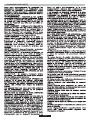
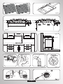
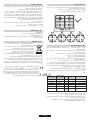
The Hob unit is fitted by attaching the Fixing Clamps supplied, using
the holes at the base of the unit.
The distance between the hob and any other unit or appliance above it
(e.g.An extractor hood) must be no less than 70 cm .(Figure 4)
When there is an accessible space between the built-in hob and the
cavity below, a dividing wall made of insulating material should be
inserted (wood or a similar material) (Figure 3).
If a hob of 60 cm is fitted above an oven which is not equipped with fan
cooling system it is recommended that openings are created within the
built in furniture to ensure correct air circulation.
The hob may be installed in any worktop which is heat resistant to a
temperature of 100°C, and has a thickness of 25-45 mm. The
dimensions of the insert to be cut out of the worktop are in shown in
Figure 2.
Metal objects in the drawer may reach high temperatures due to
air recirculation. It is therefore recommended to use an
intermediate wood panel.
When a 75 cm hob is fitted over a built in oven, the latter must be fan
cooled.
The size of these openings must be at least 300 cm2 and placed as
shown in Figure 5.
If the hob is fitted next to a cabinet on either side, the distance between
the cut out and the cabinet must be at least 15cm (see Figure 4); while
the distance between the cut out and the rear wall must be at least 7cm.
Important - The diagram in figure 1 shows how the sealant should
be applied.
1.1 BUILDING IN
1.2. SUITABLE LOCATION
A gas-powered cooking appliance produces heat and humidity in the
area in which it is installed. For this reason you should ensure good
ventilation either by keeping all natural air passages open or by
installing an extractor hood with an exhaust flue. Intensive and
prolonged use of the appliance may require extra ventilation, such as
the opening of a window or an increase in speed of the electric fan, if
you have one.
This appliance must be installed in accordance with the regulations in
force and only used in a well ventilated space. Read the instructions
before installing or using this appliance.
If a hood can not be installed, an electric fan should be fitted to an
outside wall or window to ensure that there is adequate ventilation.
The electric fan should be able to carry out a complete change of air in
the kitchen 3-5 times every hour. The installer should follow the
relevant national standards.
2. ELECTRICAL CONNECTION (FOR U.K. ONLY)
Note: We do not advocate the use of earth leakage devices with
electric cooking appliances installed to spur points because of the
«nuisance tripping» which may occur. You are again reminded that the
appliance must be correctly earthed, the manufacturer declines any
responsibility for any event occurring as a result of incorrect electrical
installation.
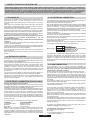
CONNECT TO SPUR TERMINAL
Green & Yellow Wire Earth Connection
Brown Wire Live Connection
Warning - this appliance must be earthed
This appliance is designed for domestic use only. Connection to the main
supply must be made by a competant electrician, ensuring that all current
regulations concerning such installations are observed.
The appliance must only be connected to a suitably rated spur point, a
3 pin 13 amp plug/socket is not suitable.A double pole switch must be
provided and the circuit must have appropriate fuse protection.
Further details of the power requirement of the individual product will
be found in the users’ instruction and on the appliance rating plate. In
the case of built-in product you are advised, should you wish to use a
longer cable than the one supplied, that a suitably rated heat resistant
type must be used.
The wiring must be connected to the mains supply as follows:
Blue Wire Neutral Connection
2.1. ELECTRICAL CONNECTION
Before connection, check the earthing system.
The section of the cable used must be of the correct size in relation to
the absorbed power of the hob.
The earth wire ( green and yellow coloured ) must be at least 10 mm
longer than the live and neutral wires.
Please check rating plate for the power details and ensure that the
power supply cord is of the type 3x0.75 mm² H05 V2V2-F.
Where the Hob is connected direct to the electricity supply, a circuit
breaker must be fitted.
If the power supply cord is damaged this is to be replaced by a qualified
engineer so as to prevent any potential risk.
Check the data on the rating plate, located on the outside of the unit, to
ensure that the supply and input voltage are suitable.
By Law, this appliance must be earthed. If this regulation is not complied
with, the Manufacturer will not be responsible for any damage caused to
persons or property. If a plug is not already attached, fit a plug
appropriate to the load indicated on the rating plate. The earth wire is
coloured yellow/green. The plug should always be accessible.
LIVE
EARTH
NEUTRAL
L
N
Power Cable
Brown Wire
Green/Yellow Wire
Blue Wire
Mains Supply
If an appliance is not fitted with a supply cord and a plug, or with other
means for disconnection from the supply mains having a contact
separation in all poles that provide full disconnection under overvoltage
category III conditions, the instructions shall state that means for
disconnection must be incorporated in the fixed wiring in accordance with
the wiring rules.
1. INSTRUCTIONS FOR THE INSTALLER
INSTALLING A DOMESTIC APPLIANCE CAN BE A COMPLICATED OPERATION WHICH IF NOT CARRIED OUT CORRECTLY, CAN SERIOUSLY
AFFECT CONSUMER SAFETY. IT IS FOR THIS REASON THAT THE TASK SHOULD BE UNDERTAKEN BY A PROFESSIONALLY QUALIFIED
PERSON WHO WILL CARRY IT OUT IN ACCORDANCE WITH THE TECHNICAL REGULATIONS IN FORCE. IN THE EVENT THAT THIS ADVICE IS
IGNOREDAND THE INSTALLATION IS CARRIED OUT BYAN UNQUALIFIED PERSON, THE MANUFACTURER DECLINES ALL RESPONSIBILITY
FORANY TECHNICALFAILURE OF THE PRODUCT WHETHER OR NOT IT RESULTS IN DAMAGE TOGOODS OR INJURY TO INDIVIDUALS.
These instructions are for qualified personnel, installation of
equipment must be in line with the relevant national standard. (For
U.K. only: by law the gas installation\commissioning must be
carried out by a "Gas Safe" installer)
The flexible tube shall be fitted in such a way that it cannot come into
contact with a moveable part of the housing unit (e.g. a drawer) and does
not pass through any space where it may become crushed/ kinked or
damaged in any way.
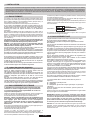
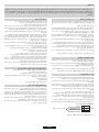
1)As illustrated, assemble parts in sequence:
All work must be carried out with the electricity supply disconnected.
For some models a conic link is furnished to outfit for the installation in
the countries where this type of link is obligatory; in picture 8 it is
pointed out how to recognize the different types of links (CY =
cylindrical, CO = conic). In every case the cylindrical part of the link
has to be connected to the hob.
When connecting the hob to the gas supply via use offlexible hoses
please ensure that the maximum distance covered by the hose does
not exceed 2 metres.
To prevent any potential damage to the hob please carry out the
installation following this sequence (picture 6):
Use only pipes,washers and sealing washers which comply with the
relevant national standards.
C: 1/2 Female GasAdaptor Conical-Cylindirical or
Cylindirical-Cylindirical
For liquid gas (cylinder gas) use pressure regulators which comply
with the relevant national standards.
B: 1/2 Seal
The rating plate on the hob shows the type of gas with which it is
designed to be used. Connection to the mains gas supply or gas
cylinder should be carried out after having checked that it is regulated
for the type of gas with which it will be supplied. If it is not correctly
regulated see the instructions in the following paragraphs to change
gas setting.
A: 1/2 MaleAdaptor Cylindirical
2.2. GAS CONNECTION

04 GB
2.3. ADAPTING THE HOB TO DIFFERENT
TYPES OF GAS
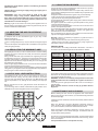
•Remove the grids and burners
•Unscrew the injector and replace it with one suitable for the gas to be
used (see gas type table)
•Insert on hexagonal spanner (7 mm) into the burner support (Figure
7)
To adapt the Hob for use with different types of gas, carry out the
following instructions:
2.4. REGULATING THE MINIMUM FLAME
When the gas supply available is LPG - the screw to set the idle flame
must be turned (clockwise) to the end stop.
After lighting the burners, turn the control knob to the minimum setting
and then remove the knob (this can easily be removed by applying
gentle pressure).
When you have carried out the new gas regulation, replace the old gas
rating plate on your appliance with one (supplied with hob) suitable for
the type of gas for which it has been regulated.
Using a small «Terminal» type screwdriver the regulating screw can
be adjusted as in Turning the screw clockwise reduces the
gas flow, whilst turning it anticlockwise increases the flow – Use this
adjustment to obtain a flame of approximately 3 to 4 mm in length and
then replace the control knob.
Figure 9.
3. USE OF HOB - USER INSTRUCTIONS
This appliance must only be used for the purpose for which it is
intended, domestic cooking, and any other use will be considered
improper and could therefore be dangerous. The Manufacturer will
not be responsible for any damage or loss resulting from improper
use.
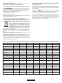
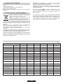
Table A
Burner Type
Ø pan/pot
(cm)
AUX
SR
R
DC 4 kW DUAL
10 - 18
12 - 22
16 - 26
16 - 26
Auxiliary
Semi Rapid
Rapid
Power
(kW)
1,00
1,75
2,70
4,00
G20/20 mbar
(methane)
95 l/h
167 l/h
257 l/h
381 l/h
G30/28-30 mbar
(LPG)
73 g/h
127 g/h
196 g/h
291 g/h
DC 4,2 kW DUAL
16 - 26
4,20
400 l/h
306 g/h
DC 5 kW DUAL
16 - 26
5 NG
4,6 LPG
476 l/h
364 g/h
4. MAINTENANCE AND CLEANING
Cleaning and user maintenance shall not be made by children without
supervision
When cleaning the enamelled, varnished or chrome sections, use
warm soapy water or a non caustic detergent. For stainless steel use
an appropriate cleaning solution.
Before cleaning the hob, ensure the appliance has cooled down.
Remove the plug from the socket or (if connected directly) switch off
the electricity supply.
Never use abrasives, corrosive detergents, bleaching agents or
acids. Avoid any acid or alkaline substances (lemon, juice, vinegar
etc.) on the enamelled, varnished or stainless steel sections.
The burners can be cleaned with soapy water. To restore their original
shine, use a household stainless steel cleaner. After cleaning, dry the
burners and replace.
It is important the Burners are replaced correctly.
For smaller containers the gas burner should be regulated so that the
flame does not overlap the base of the pan. Vessels with a concave or
convex base should not be used.
WARNING: If a flame is accidentally extinguished, turn the knob
to the off position and do not attempt to re-ignite if for at least 1
minute.
Such operation must be carried out only by qualified Service
Engineers.
If over the years the gas taps become stiff to turn it is necessary to
lubricate them.
2)Tighten the joints with the spanner, remembering to twist the
pipes into position.
3)Attach fitting C to mains gas supply using rigid copper pipe or
flexible steel pipe.
IMPORTANT: carry out a final check for leaks on the pipe
connections using a soapy solution.
Also, make sure that the flexible pipe cannot come into contact
with a moving part of the cabinet (eg.adrawer) and that it is not
situated where it could be damaged.
NEVER USE A FLAME.
Warning: If gas can be smelt in the vicinity of this appliance turn off
the gas supply to the appliance and call the engineer directly. Do not
search for a leak with a naked flame.
Before using burner, be sure, grid perimeters center the burner as
below figure.
If you are using Cast Iron Grids; underneath the grid, position of it is
stated. Be sure for the exact grid is used in correct position.
3.1. USING THE GAS BURNER
To ignite the burners, place a lighted taper close to the burner, press in
and turn the control knob anti-clockwise.
• İgnite the burner by pressing the sparker button.
If the burners have not been used for a couple of days, wait for a few
seconds before lighting the burner, this will allow any air present in the
pipes to escape.
For appliances fitted with electronic ignition carry out the following:
• Push in and turn the knob anticlockwise to the ignition symbol.
For hobs fitted with automatic ignition simply push in and turn the knob
to the ignition symbol.
The ignition system will continue to generate sparks as long as the
control knob is being pressed.
If the burner has not ignited within 5 seconds, turn the knob to the 0
position and repeat the operation.
For models fitted with a safety tap (which cuts-off the flow of gas if the
flame is accidentally extinguished) the burners are ignited and
described above, but care must be taken.
Prior to switching on the gas hob ensure that the burners and burner
caps are correctly placed within their position.
- While pushing in the button ignite the burner by using a lighter and
keep button pushed in 5 seconds after ignition.
- Push in and turn the knob anti-clockwise to the ignition symbol,
GENERALADVISE
For best results, use cooking vessels with a flat surface. The size of
the surface should match the gas burner side as follows.TableA.
Warning: If there is no electricity on appliance, to ignite the burner a
lighter should be used;

05 GB
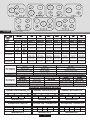
Table 1
• WEEE shall not be treated as household waste.
• WEEE shall be handed over to the relevant collection points
managed by the municipality or by registered companies. In many
countries, for large WEEE, home collection could be present.
• When you buy a new appliance, the old one may be returned to the
retailer who has to collect it free of charge on a one-to-one basis, as
long as the equipment is of equivalent type and has the same
functions as the supplied equipment.
Individuals can play an important role in ensuring that WEEE does not
become an environmental issue; it is essential to follow some basic
rules:
This appliance is marked according to the European
directive 2012/19/EU on Waste Electrical and
Electronic Equipment (WEEE). WEEE contains both
polluting substances (which can cause negative
consequences for the environment) and basic
components (which can be re-used). It is important to
have WEEE subjected to specific treatments, in order
to remove and dispose properly all pollutants, and
recover and recycle all materials.
6. PROTECTION OF THE ENVIRONMENT
The Manufacturer will not be responsible for any inaccuracy resulting
from printing or transcript errors contained in this brochure. We
reserve the right to carry out modifications to products as required,
including the interests of consumption, without prejiudice to the
characteristics relating to safety or function.
The appliance complies with European Directive 2009/142/EC (GAD)
and starting from 21/04/2018 with Gas Appliances Regulation
2016/426 (GAR).
By placing the mark on this product, we are confirming
compliance to all relevant European safety, health and environmental
requirements which are applicable in legislation for this product.
Declaration of compliance: This equipment, in the parts intended to
come into contact with food, complies with the regulations laid down in
EEC directives 89/109.
5. AFTERCARE
Before calling out a Service Engineer please check the following:
• that the plug is correctly inserted and fused;
• that the gas supply is not faulty.
If the fault cannot be detected:
Switch off the appliance and call the After Service Centre. DO NOT
TAMPER WITH THE APPLIANCE.
Chromed grids and burners have a tendency to discolour with use.
This does not jeopardize the functionality of the hob.
Our After Sales Service Centre can provide spare parts if required.
Chromed grids and burners
This appliance has been designed for non-professional, i.e. domestic, use.
Burner Plate
Burner
Type
FFD
Aux 1kW
Sr 1,75 kW
R 2,7 kW
Dc 4 kW Dual
Dc 4,2 kW Dual
Dc 5 kW Dual
Nominal Heat Input
G20/20 mbar
G30/28-30 mbar
Installation Class
Voltage V/Frequency Hz
Electrical Input Power
Electric Ignition
Product Dimension
3
1
YES
595x510
3
1
YES
595x510
3
1
YES
595x510
3
1
YES
595x510
UH60MF
YES
1
UH60MF
YES
1
UH60MF
YES
1
UH60MF
YES
1
4 Gas
Aux/2SR/R
4 Gas
Aux/SR/R/DC 4 Dual
4 Gas
Aux/SR/R/DC 4,2 Dual
4 Gas
Aux/SR/R/DC 5 Dual
2
1
1
1
1
1
1
1
-
1
-
-
-
-
1
-
-
-
-
1
7,2 kW
686 l/h
524 g/h
9,45 kW
900 l/h
688 g/h
9,65 kW
920 l/h
702 g/h
10,45 kW
10,05 kW
996 l/h
731 g/h
220-240 V/ 50-60 Hz 220-240 V/ 50-60 Hz 220-240 V/ 50-60 Hz 220-240 V/ 50-60 Hz 220-240 V/ 50-60 Hz 220-240 V/ 50-60 Hz
3
1
YES
745x510
UH75MF
YES
1
5 Gas
DC/2R/SR/AUX
1
2
-
-
1
13,15 kW
12,75 kW
1253 l/h
928 g/h
3
1
YES
745x510
UH75MF
YES
1
5 Gas
DC/2SR/SR/AUX
2
1
-
-
1
12,2 kW
11,8 kW
1163 l/h
859 g/h
3
1
YES
595x510
UH60MF
YES
1
3 Gas
Aux/R/DC 4 Dual
-
1
1
-
-
8,7 kW(NG)
8,3 kW(LPG)
829 l/h
604 g/h
220-240 V/ 50-60 Hz

06 FR
CONSIGNES DE SÉCURITÉ

07 FR
Le meuble ou le support dans lequel doit être encastrée la table, ainsi
que les parois du meuble qui pourraient juxtaposer celui-ci, doivent être
d'une matière résistant à une température élevée (jusqu'à 100°C) et
d'une épaisseur comprise entre 25 et 45 cm.
Les dimensions d'encastrement sont indiquées sur le .schéma 2
Si, en fonction de l'installation de la table, la partie inférieure de son
caisson se trouve à proximité d'une zone normalement accessible lors
de manipulations et/ou de rangements, placer une cloison (bois ou
similaire) pour éviter tous risques de brûlure ou de détérioration
().schéma 3
Si la plaque est installée à côté d'un meuble de l'un ou l'autre côté, la
distance entre la découpe et le placard doit être d'au moins 15 cm (voir
figure 4). La distance entre la découpe et la paroi arrière doit être d'au
moins 7 cm. La distance entre la table et tout autre appareil ou meuble
situé au dessus (par exemple une hotte) doit être au moins de 70 cm
().voir schéma 4
Les objets en métal contenus dans le tiroir peuvent atteindre une
température très élevée, à cause du système de recirculation d'air.
Il est donc recommandé d'interposer un panneau en bois.
Attention : Lors de la mise en place, un soin particulier doit être
porté au joint entourant le bord de la table afin d'éviter toute
infiltration dans le meuble support ( ).schéma 1
Lors de la mise en place du joint sur la partie arrière, veiller à ne pas
obstruer les passages d'air nécessaires à la combustion.
Si une table de 60 cm de large est installée au-dessus d'un four qui
n'est pas équipé de ventilation tangentielle, il est recommandé de créer
des ouvertures dans le caisson de cuisine pour faire ainsi circuler l'air.
La taille de ces ouvertures doit être au moins de et placées
comme indiqué sur le .schéma 5
300 cm²
Si c'est une table de 75cm de large qui est installée au-dessus du four,
ce dernier doit être équipé d'une ventilation tangentielle.
Le caisson de la table est équipé en dessous de 4 emplacements
prévus pour recevoir les brides de fixation destinées à l'immobilisation
de la table sur le meuble. Placer les 4 brides de fixation de manière à ce
que la table de travail soit parfaitement plaquée au meuble.
1.1. ENCASTREMENT
1.2. CARACTERISTIQUES REQUISES
Cet appareil doit être installé en conformité avec la réglementation en
vigueur et utilisé uniquement dans un espace ventilé. Lisez les
instructions avant d'installer ou utiliser cet appareil.
S'il n'est pas possible d'installer une hotte, une VMC devrait être
installée sur un mur donnant sur l'extérieur ou sur une fenêtre.
La VMC devrait être en mesure d'apporter un changement complet de
l'air de la cuisine 3 à 5 fois par heure. L'installateur doit installer la VMC
conformément aux règles en vigueur dans le pays d'installation.
Une utilisation intensive et prolongée de l'appareil peut requérir une
ventilation plus importante, telle que l'ouverture d'une fenêtre ou une
puissance d'aspiration plus intense de la VMC si vous en êtes
équipés.
1. INSTALLATION
La mise en place fonctionnelle des appareils ménagers dans leur environnement est une opération délicate qui, si elle n'est pas correctement
effectuée, peut avoirde graves conséquences sur la sécurité des consommateurs. Dans ces conditions, il est impératif de confier cette tâche à
un professionnel qui la réalisera conformément aux normes techniques en vigueur. Si malgré cette recommandation, le consommateur
réalisait lui-même l'installation, le constructeur déclinerait toute responsabilité en cas de défaillance technique du produit entraînant ou non
des dommages auxbiens et/ou aux personnes.
2.1. RACCORDEMENT ELECTRIQUE
Lorsque la table de cuisson est reliée directement à
l'approvisionnement en électricité, un disjoncteur doit être installé.
La prise devrait toujours être accessible.
Si le cordon d'alimentation est endommagé, il doit être remplacé par
un technicien qualifié afin d'éviter tout risque potentiel.
Le fil de terre est de couleur jaune / vert.
Vérifier les données sur la plaque signalétique, située à l'extérieur de
l'unité, pour assurer que l'alimentation et le voltage conviennent.
Si une prise n'est pas déjà fournie, installer une prise appropriée pour
la charge indiquée sur la plaque signalétique.
Attention : vérifier la continuité de la terre de l'installation avant
de procéder au raccordement. Notre responsabilité ne saurait
être engagée pour tout incident ou ses conséquences
éventuelles qui pourraient survenir à l'usage d'un appareil non
relié à la terre, ou relié à une terre dont la continuité serait
défectueuse.
"L'installation recevant l'appareil cité en référence doit être
conforme à la norme en vigueur dans le pays d'installation".
Le constructeur décline toute responsabilité en cas de non
respect de cette disposition.
Avant le branchement, vérifier le système de mise à la terre.
Le fil de terre (couleur vert et jaune) doit être au moins 10mm plus long
que les fils de phase et neutre.
La section du câble utilisé doit être de la bonne taille par rapport à la
puissance absorbée de la table de cuisson.
Veuillez vérifier la plaque signalétique pour les détails de puissance et
veiller à ce que le cordon d'alimentation électrique soit de type 3x0.75
mm² l'H05 V2V2-F.
PHASE
TERRE
NEUTRE
L
N
Câble
lectrique
d’alim
é
Fil Marron
Fil Vert/jaune
Fil Bleu
Alimentation
Un système de déconnexion doit être incorporé dans le compteur
conformément aux règles de câblage.
2.2. RACCORDEMENT GAZ
En vigueur dans le pays d'installation. Une attention
De ventilation.
La plaque signalétique sur la plaque indique le type de gaz qui doit
être utilisé. Le raccordement au réseau d'approvisionnement en gaz
ne doit être effectuée qu'après avoir vérifié qu'il est réglé pour le type
de gaz avec lequel il sera distribué. S'il n'est pas correctement réglé,
voir les instructions dans les paragraphes suivants pour modifier le
réglage du gaz.
L'appareil doit être installé et raccordé conformément aux règles
particulière sera accordée aux dispositions applicables en matière
Tous les travaux d'installation doivent être effectués avec l'électricité
déconnectée.
Pour le gaz liquide (bouteille de gaz), utiliser des régulateurs de
pression conformes aux normes en vigueur.
Utilisez uniquement des tuyaux, des rondelles et des rondelles
d'étanchéité conformes aux normes en vigueur.
Pour certains modèles un lien conique est fourni pour installation
l'appareil, dans les pays où ce type de lien est obligatoire ; sur le
schéma 8, il est indiqué comment reconnaître les différents types de
liens (CY = cylindrique, CO = conique). Dans tous les cas, la partie
cylindre du lien doit être connecté à la table.
lde'
Lorsque vous connectez la table de cuisson à l'alimentation du gaz via
l'utilisation de tuyaux flexibles, veuillez faire en sorte que la distance
maximum couverte par le tuyau ne dépasse pas 2 mètres.
Le tube flexible doit être installé de manière à ne pas entrer en contact
avec un élément mobile de la cuisine (par exemple un tiroir) et à ne
pas passer dans un espace pouvant être encombré.
Pour éviter tout dommage potentiel à la table de cuisson, veuillez
effectuer l'installation suivant les indications du schéma 6.
1) Comme illustré dans le schéma, assembler les pièces en
séquence :
A: ½ Adaptateur Cylindrique mâle
B: ½ Obturation
C: ½ Adaptateur gaz Femelle conique-cylindrique ou cylindrique-
cylindrique.
2) Serrer les joints avec des clés à molette, pensez à placer les
tuyaux en position.
3) Fixer le raccord C au réseau d'approvisionnement en gaz à l'aide
dun' tuyau rigide ou en acier flexible.
IMPORTANT: effectuer une dernière vérification pour détecter
les fuites sur les raccords de tuyauterie en utilisant une solution
savonneuse. Ne jamais utiliser une flamme. Aussi, assurez vous
que le tuyau flexible ne peut pas entrer en contact avec une
partie mobile du meuble de cuisine (par exemple un tiroir) et qu'il
ne se trouve pas à un endroit où il pourrait être endommagé.
Attention: Si vous sentez des émanations de gaz en provenance de
l'appareil, coupez immédiatement l'alimentation en gaz et appelez
directement une personne qualifiée. Ne cherchez pas une fuite à
l'aide d'une flamme.

Table A
Type de brûleurs
Ø
(cm)
casserole
AUX
SR
R
DC 4 kW DUAL
10 - 18
12 - 22
16 - 26
16 - 26
Brûleur auxiliaire
Brûleur semi-rapide
Brûleur rapide
Puissance
totale
(kW)
1,00
1,75
2,70
4,00
G20/20 mbar
(Gaz de naturel:
Méthane)
95 l/h
167 l/h
257 l/h
381 l/h
G30/28-30 mbar
(Butane/Propane)
73 g/h
127 g/h
196 g/h
291 g/h
DC 4,2 kW DUAL
16 - 26
4,20
400 l/h
306 g/h
DC 5 kW DUAL
16 - 26
5 NG
4,6 LPG
476 l/h
364 g/h
08 FR
2.3. ADAPTER LA TABLE A DIFFERENTS
TYPES DE GAZ
Pour adapter la table de cuisson à différents types de gaz, veuillez
• Visser le/les injecteurs à fond
• Insérez une clé à pipe (7 mm) dans le support du brûleur ( )schéma 7
• Régler la bague d'air
exécuter les instructions suivantes:
• Enlever les grilles, chapeaux et corps de brûleurs
• Replacer les corps de brûleurs, le chapeau de brûleur et les grilles.
• Dévisser le/les injecteurs et le/les remplacer par un/des injecteurs
adaptés au gaz à utiliser (voir le type de gaz préconisé sur la table)
2.4. REGULER LA FLAMME AU MINIMUM
Lorsque l'approvisionnement en gaz disponible est du
butane/propane (gaz de bouteilles), la vis pour régler la flamme au
ralenti doit être tournée dans le sens des aiguilles d'une montre,
jusqu'à la butée.
Lorsque vous avez effectué la régulation du gaz, remplacer
l'ancienne plaque signalétique de votre appareil avec celle adaptée
au type de gaz installé (fournie avec plaque de cuisson).
Après l'allumage du brûleur, tourner le bouton de commande au
réglage minimum, puis enlever la manette de commande (ce qui
peut facilement être enlevé en appliquant une légère pression).
En utilisant un petit «Terminal » type tournevis, la vis de réglage peut
être ajustée (cf Schéma 9). En tournant la vis dans le sens des
aiguilles d'une montre, cela réduit le débit de la flamme, alors qu'en
tournant dans le sens inverse, cela l'augmente. Utilisez ce réglage
pour obtenir une flamme d'environ 3à4mmdelongueur, puis
replacer la manette de commande.
3. UTILISATION DE LA TABLE
Cet appareil ne doit être utilisé que pour des fins pour lesquelles il est
destiné : la cuisson domestique. Toute autre utilisation sera
considérée comme abusive et peut donc être dangereuse. Le
fabricant ne sera pas responsable pour tout dommage ou perte
découlant d'une utilisation abusive.
4. MAINTENANCE ET ENTRETIEN
Avant de nettoyer la table de cuisson, assurez-vous que cet appareil
est refroidi. Retirez la fiche de la prise ou (s'il est connecté
directement), éteindre l'alimentation d'électricité.
Lors du nettoyage de l'émail, vernis ou des sections chromées,
utilisez de l'eau chaude savonneuse ou un détergent non corrosif.
Pour l'acier inoxydable, utilisez une solution de nettoyage appropriée.
Grilles chromées et brûleurs
Le nettoyage et l'entretien par l'utilisateur ne doit pas être fait par des
enfants sans surveillance.
Ne jamais utiliser de produits abrasifs, de détergents corrosifs, agents
de blanchiment ou d'acides. Éviter les substances acides ou alcalines
(citron, jus, vinaigre etc…) sur l'émail ou l'acier.
Les brûleurs peuvent être nettoyés avec de l'eau savonneuse. Pour
restaurer leur éclat d'origine, utilisez un nettoyant ménager pour acier
inoxydable.Après nettoyage, séchez les brûleurs et les replacer.
Il est important que les brûleurs soient remplacés correctement
à leur position.
Les grilles chromées et les brûleurs ont tendance à foncer à
l'utilisation. Il s'agit d'un phénomène normal et inévitable, mais elle ne
compromet pas la fonctionnalité de la table de cuisson.
Si besoin, des pièces de rechange sont disponibles dans notre centre
de service après-vente.
Si au fil des années les robinets de gaz deviennent raides, il est
nécessaire de les lubrifier.
Cette opération ne doit être effectuée que par un technicien
agréé.
Pour les petites casseroles/poêles, le brûleur à gaz doit être réglé de
telle manière que la flamme ne chevauche pas le fond de la casserole.
Les récipients à fond concave ou convexe ne doivent pas être utilisés.
ATTENTION: Si un brûleur est accidentellement éteint, tournez le
bouton vers la position fermée et ne pas tenter de relancer
pendant au moins 1 minute.
Avant d'utiliser le brûleur, assurez-vous que les périmètres de la grille
centrent le brûleur tel qu'illustré à la figure ci-dessous.
Si vous utilisez des grilles en fonte; sous la grille, leur position est
indiquée. Assurez-vous que la grille adéquate est utilisée dans la
bonne position.
3.1. UTILISATION DU BRÛLEUR À GAZ
Pour les appareils équipés d'allumage électronique, effectuer les
opérations suivantes:
Si les brûleurs n'ont pas été utilisés depuis quelques jours, attendre
quelques secondes avant d'allumer le brûleur, ce qui permettra l'air
éventuellement présent dans les tuyaux de s'échapper.
Pour allumer les brûleurs, placez une flamme (allume-feu, allumette,
briquet etc…) près du brûleur, appuyez et tournez la manette de
commande.
Pour les tables de cuisson équipées d'allumage électronique intégré,
il suffit de pousser et tourner le bouton sur le symbole d'allumage.
Si le brûleur ne s'enflamme pas dans les 5 secondes, tournez le
bouton vers la position 0 et répéter l'opération.
• Pousser et tourner la manette de commande sur le symbole
d'allumage.
•Allumer le brûleur en appuyant sur le bouton d'allumage
Le système d'allumage continuera à produire des étincelles aussi
longtemps que le robinet de gaz est actionné.
Pour les modèles équipés d'un robinet de sécurité par thermocouple
(qui coupe l'écoulement du gaz si la flamme est accidentellement
éteinte), les brûleurs sont allumés et décrit ci-dessus, mais il faut
prendre soin de garder la manette de commande enfoncée pendant 5
ou 6 secondes après que la flamme soit allumée.
ATTENTION : Avant d'allumer la table gaz, veillez à ce que les
brûleurs et les chapeaux de brûleur soient correctement placés dans
leur position.
- Appuyez et tournez le bouton dans le sens contraire des aiguilles
d'une montre jusqu'au symbole ,d'allumage
- En appuyant sur l , allumez le brûleur à l'aide d'un briquet
et maintenez 5 secondes après la mise
en marche.
la manette
la manette enfoncée pendant
CONSEIL
Pour de meilleurs résultats, la taille de casseroles à fond plat doit
correspondre à la taille des brûleurs comme suit :
Attention: s'il n'y a pas d'électricité sur l'appareil, allumer le brûleur en
utilisant un briquet;

(DEEE). Les DEEE contiennent à la fois des
substances polluantes (qui peuvent avoir des
conséquences négatives sur l'environnement) et
des éléments de base (réutilisables). Il est important
de soumettre les DEEE à des traitements spécifiques,
en vue d'extraire et d'éliminer de façon appropriée toutes les
substances polluantes, puis de récupérer et recycler tous les
matériaux.
Chacun peut jouer un rôle important quant à la protection de
l'environnement contre les DEEE. Pour atteindre cet objectif, il est
impératif de suivre quelques règles élémentaires :
• Lorsque vous achetez un nouvel appareil, vous devez retourner
l'ancien au vendeur qui le récupère gratuitement, au cas par cas, à
condition que l'équipement soit de type équivalent et possède les
mêmes fonctions que celui fourni.
• Les DEEE ne doivent pas être traités comme des déchets
ménagers.
• Ils doivent être remis aux points de collecte appropriés gérés par la
municipalité ou par des sociétés immatriculées. Dans plusieurs pays,
il est possible de collecter à domicile les DEEE volumineux.
Le présent appareil est marqué conformément à la
directive 2012/19/UE relative aux déchets
d'équipements électriques et électroniques
6. PROTECTION DE L'ENVIRONNEMENT
09 FR
Table 1
5. ASSISTANCE TECHNIQUE
Avant d'appeler le Service d'Assistance Technique, vérifier les points
suivants:
• La prise est bien insérée ;
• L'approvisionnement en gaz n'est pas défectueux.
Si la panne ne peut être identifiée:
Éteignez l'appareil (ne pas l'utiliser) et appeler le Service d'Assistance
Technique.
L'appareil est conforme à la Directive européenne 2009/142/CE
(GAD) et à partir du 21/04/2018, à la Réglementation sur les appareils
à gaz 2016/426 (GAR).
Le constructeur décline toute responsabilité concernant
d'éventuelles inexactitudes imputables à des erreurs d'impression ou
de transcription contenue dans cette notice. Le constructeur se
réserve le droit de modifier les produits en cas de nécessité, même
dans l'intérêt de l'utilisation, sans causer de préjudices aux
caractéristiques de fonctionnement de sécurité des appareils.
En utilisant le symbole sur ce produit, nous déclarons sur notre
propre responsabilité que ce produit est conforme à toutes les
normes Européennes relatives à la sécurité, la santé et à
l’environnement.
Déclaration de conformité: cet équipement, dans les parties
destinées à entrer en contact avec les aliments, est conforme aux
normes fixées par les directives CEE 89/109.
Cet appareil a été dessiné pour un usage non professionnel, usage domestique uniquement
Aux 1kW
Sr 1,75 kW
R 2,7 kW
Dc 4 kW Dual
Dc 4,2 kW Dual
Dc 5 kW Dual
Entrée de chaleur nominale
G20/20 mbar
G30/28-30 mbar
Classe d'installation
Voltage / Frequency V / Hz
Puissance électrique
Allumage électronique intégré
Dimensions appareil (LxP) mm
Plaque de brûleur
Brûleur
Type
FFD
3
1
Oui
595x510
3
1
Oui
595x510
3
1
Oui
595x510
3
1
Oui
595x510
UH60MF
Oui
1
UH60MF
Oui
1
UH60MF
Oui
1
UH60MF
Oui
1
4 Gas
Aux/2SR/R
4 Gas
Aux/SR/R/DC 4 Dual
4 Gas
Aux/SR/R/DC 4,2 Dual
4 Gas
Aux/SR/R/DC 5 Dual
2
1
1
1
1
1
1
1
-
1
-
-
-
-
1
-
-
-
-
1
7,2 kW
686 l/h
524 g/h
9,45 kW
900 l/h
688 g/h
9,65 kW
920 l/h
702 g/h
10,45 kW
10,05 kW
996 l/h
731 g/h
220-240 V/ 50-60 Hz 220-240 V/ 50-60 Hz 220-240 V/ 50-60 Hz 220-240 V/ 50-60 Hz 220-240 V/ 50-60 Hz 220-240 V/ 50-60 Hz
3
1
Oui
745x510
UH75MF
Oui
1
5 Gas
DC/2R/SR/AUX
1
2
-
-
1
13,15 kW
12,75 kW
1253 l/h
928 g/h
3
1
Oui
745x510
UH75MF
Oui
1
5 Gas
DC/2SR/SR/AUX
2
1
-
-
1
12,2 kW
11,8 kW
1163 l/h
859 g/h
3
1
Oui
595x510
UH60MF
Oui
1
3 Gas
Aux/R/DC 4 Dual
-
1
1
-
-
8,7 kW(NG)
8,3 kW(LPG)
829 l/h
604 g/h
220-240 V/ 50-60 Hz

10
Figure 1
1/2 GAS
CONICAL
C
AB
INJECTOR
Figure 6
Figure 7
Figure 8
60
75
35
mm
25 - 45 mm
min. 5 mm
min. 10 mm
min.
50 mm
25 - 45 mm
min. 5 mm
Figure 3
min.
50 mm
35
mm
min. 10 mm
min.
50 mm
min.
50 mm
120 cm
2
180 cm
2
Figure 5
Min. 70 cm
Figure 4
560 mm
480 mm
min 70 mm
min 600 mm
min 50 mm
min 170 mm (60 cm)
min 250 mm (75 cm)
Figure 2
INJECTEUR
CONICAL
CYLINDRICAL
CYLINDRICAL

11
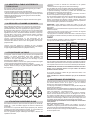
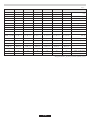
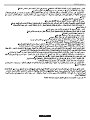
GAS TYPEHOBS
II2HS3B/P
L5 L6
DC 5
Kw
Dual
L7
DC 5
Kw
Dual
Dc 4 kW Dual
4 2,3
Max - Min Max - Min Max - Min Max - Min Max - Min Max - Min Max - Min
72X
(1Kw-0,3Kw)
70X
(1Kw-0,3Kw)
74F1
(1Kw-0,3Kw)
72F1
(1Kw-0,3Kw)
50
(1Kw-0,3Kw)
46
(1Kw-0,34Kw)
43H2
(1Kw-0,39Kw)
97Z
(1.75Kw-0.44Kw)
102F3
(1.75Kw-0.44Kw)
65
(1.75Kw-0.44Kw)
61
(1.75Kw-0.51Kw)
58M
(1.75Kw-0.58Kw)
91Z
(1.75Kw-0.44Kw)
98Y
(1.75Kw-0.44Kw)
109Y
(2.7Kw-0.75Kw)
115F2
(2.7Kw-0.75Kw)
80
(2.7Kw-0.75Kw)
78
(2.7Kw-0.83Kw)
73S
(2.7Kw-0.96Kw)
110F3
(2.7Kw-0.75Kw)
120F2
(2.7Kw-0.75Kw)
138H3-70H1
(4Kw-2.3Kw)
128K-68F1
(4Kw-2.3Kw)
93-44
(4Kw-2.3Kw)
86-41
(4Kw-2.4Kw)
68F4-41H2
(4Kw-2.6Kw)
132H3-65H1
(4Kw-2.3Kw)
132F3-68F1
(4Kw-2.3Kw)
140H3-70H1
(4.2Kw-2.3Kw)
130K-68F1
(4.2Kw-2.3Kw)
95-44
(4.2Kw-2.3Kw)
90-41
(4.2Kw-2.4Kw)
73F4-41H2
(4.2Kw-2.3Kw)
135H3-65H1
(4.2Kw-2.3Kw)
143F3-68F1
(4.2Kw-2.3Kw)
153H3-70H1
(5Kw-2.3Kw)
150F3-68F1
(5Kw-2.3Kw)
98-47
(4.6Kw-2.3Kw)
95-41
(4.6Kw-2.4Kw)
78F4-41H2
(4.6Kw-2.4Kw)
150H3-65H1
(5Kw-2.3Kw)
148F2-68F1
(5Kw-2.3Kw)
Dc 4,2 kW Dual
Dc 5 kW Dual
4,2
2,3
5 2,3
Efficiency Decleration 2016/426
UH60MF 5kW DIAMOND (L1)
AUX SR R DC
-
55 % 57,6 % 57,6 %
SINGLE BURNER EFFICENCY
MEDIUM %56,7
UH60MF - BIG REAR (L3, L5)
AUX SR R DC
-
60 % 55,9 % 54,3 %
SINGLE BURNER EFFICENCY
MEDIUM %56,7
UH60MF - BIG FRONT (L2)
AUX SR R DC
-
60 % 55,9 % 54,3 %
SINGLE BURNER EFFICENCY
MEDIUM %56,7
UH75MF 5kW - CENTRAL (L6)
AUX SR R DC
-
57,6 % 54,3 % 59,4 %
SINGLE BURNER EFFICENCY
MEDIUM %56,5
R
54,5 %
UH75MF 5kW - LATERAL (L7)
AUX SR SR DC
-
57,1 % 57,1 % 55,9 %
SINGLE BURNER EFFICENCY
MEDIUM %55,7
R
52,8 %
DC 5
kw
Dual
L1
DC
4,2 Kw
Dual
L2
DC 4
Kw
Dual
L3
DC 5
kw
Dual
L4
UH60MF 5kW 3 GAS (L4)
AUX R DC
-
57,6 % 52,8 %
SINGLE BURNER EFFICENCY
MEDIUM %55,2
II2EK3B/P
G30/G31 30/30 mbar
G25.1 25 mbar
G30/G31 30/30 mbar

05 AE
طﻘﻓ ﻲﻟزﻣﻟا مادﺧﺗﺳﻼﻟ ، ﻲﻓاﺗﺣﻻا ﻏ مادﺧﺗﺳﻼﻟ زﺎﺟﻟا اذ مﻣﺻﺗ مﺗ
ﺔﻟوﺎط ١
دﻗاوﻣﻟا
جذوﻣ
زﺎﻐﻠﻟ ﺔاﺣﻟا ﺔﻣﻼﺳ
Aux 1kW
Sr 1,75 kW
R 2,7 kW
Dc 4 kW Dual
Dc 4,2 kW Dual
Dc 5 kW Dual
3
1
595x510
3
1
595x510
3
1
595x510
3
1
595x510
UH60MF
1
UH60MF
1
UH60MF
1
UH60MF
1
٤ زﺎﻐﻟا
Aux/2SR/R
٤ زﺎﻐﻟا
Aux/SR/R/DC 4 Dual
٤ زﺎﻐﻟا
Aux/SR/R/DC 4,2 Dual
٤ زﺎﻐﻟا
Aux/SR/R/DC 5 Dual
2
1
1
1
1
1
1
1
-
1
-
-
-
-
1
-
-
-
-
1
طاو وﻠﻛ 7,2
س / ﺗﻟ ٦٨٦
ﺔﻋﺎﺳ / غ ٥٢٤
طاو وﻠﻛ ٩٬٤٥
س / ﺗﻟ ٩٠٠
ﺔﻋﺎﺳ / غ ٦٨٨
طاو وﻠﻛ ٩٬٦٥
س / ﺗﻟ ٩٢٠
ﺔﻋﺎﺳ / غ ٧٠٢
طاو وﻠﻛ ١٠٬٤٥
طاو وﻠﻛ ١٠٬٠٥
س / ﺗﻟ ٩٩٦
ﺔﻋﺎﺳ / غ ٧٣١
3
1
745x510
UH75MF
1
٥ زﺎﻐﻟا
DC/2R/SR/AUX
1
2
-
-
1
طاو وﻠﻛ ١٣٬١٥
طاو وﻠﻛ ١٢٬٧٥
س / ﺗﻟ ١٢٥٣
ﺔﻋﺎﺳ / غ ٩٢٨
3
1
745x510
UH75MF
1
٥ زﺎﻐﻟا
DC/2SR/SR/AUX
2
1
-
-
1
طاو وﻠﻛ ١٢٬٢
طاو وﻠﻛ ١١٬٨
س / ﺗﻟ ١١٦٣
ﺔﻋﺎﺳ / غ ٨٥٩
3
1
595x510
UH60MF
مﻌ
1
٣ زﺎﻐﻟا
Aux/R/DC 4 Dual
-
1
1
-
-
طاو وﻠﻛ
طاو وليك 8,3
8,7
س / ﺗﻟ ٨٢٩
ﺔﻋﺎﺳ / غ ٦٠٤
دﻋﺎﺳﻣ دﻗوﻣ
ﻊﺳﻟا }ﺑﺷﻟا دﻗوﻣﻟا
ﻊﺳ دﻗوﻣ
مﻌ مﻌ مﻌ مﻌ مﻌ مﻌ
ﺔﻠﻛﻟا ةوﻘﻟا
بﻛﺗﻟا ﺔﺋﻓ
زﺗ / سﻣﺎﺧﻟا ددﺗﻟا / دﺟﻟا
ﺔﺋﺎﺑﻛ ةوﻗ
لﻣﺎﻛﺗﻣﻟا ﻲوﺗﻛﻟﻹا لﺎﻌﺷﻹا
زﺎﺟﻟا دﺎﻌﺑأ()WxDمﻣ
(NG)
(LPG)
)(G20 / 20 mbar نﺎﺛﻣﻟا :ﻲﻌﺑطﻟا زﺎﻐﻟا
)(G30 / 28-30 mbar نﺎﺑوﺑﻟا / نﺎﺗوﺑﻟا
٢٢٠-٢٤٠ تﻟوﻓ /
50-60 زﺗ
٢٢٠-٢٤٠ تﻟوﻓ /
50-60 زﺗ
٢٢٠-٢٤٠ تﻟوﻓ /
50-60 زﺗ
٢٢٠-٢٤٠ تﻟوﻓ /
50-60 زﺗ
٢٢٠-٢٤٠ تﻟوﻓ /
50-60 زﺗ
٢٢٠-٢٤٠ تﻟوﻓ /
50-60 زﺗ
٢٢٠-٢٤٠ تﻟوﻓ /
50-60 زﺗ
مﻌمﻌمﻌمﻌمﻌمﻌمﻌ

04 AE
ﺔﻟوا
دﻗوﻣﻟا عو
AUX
10 - 18
12 - 22
16 - 26
ةدﻋﺎﺳﻣ دﻗوﻣﻟا
SRﻊﺳ }ﺑﺷ دﻗوﻣﻟا
Rﻊﺳﻟا دﻗوﻣﻟا
ﺔﻠﻛﻟا ةوﻘﻟا
1,00
1,75
2,70
3 /28-3
(نﺎﺑوﺑﻟا / نﺎﺗوﺑﻟا)
.3
ﺧآ مادﺧﺗـــﺳا يأ .ﻲﻟزﻣﻟا ﻲطﻟا :طـــﻘﻓ }ﻟ ﺔﺻﺻﺧﻣﻟا ضاﻏﻸﻟ زﺎﺟﻟا اذ مادﺧﺗــﺳا بﺟ
ﻊﺻﻣﻟا .ا
طﺧ نوﻛ دﻗو ﺎ
ﺋﺳﻣ ﺑﺗﻌﺳ
مادﺧﺗﺳﻻا وﺳ نﻣ ﺄﺷﺗ ةﺎﺳﺧ وأ ﺿ يأ نﻋ ﺔﻟوؤﺳﻣ لﻣﺣﺗ نﻟ
بﺟ لﻔﺳﻷا ﻲﻓ لﺎﺛﻣﻟا ﺷ ﺎﻣﻛ طﺳوﻟا ﻲﻓ ﺔﻛﺑﺷﻟا نأ نﻣ دﻛﺄﺗﻟا
ﺎ
ﺑﻟ ﻊﺿ ،دـﻗوﻣﻟا لﺎﻌﺷﻹ )ﺔﻠﻌـﺷﻣ ، ﺎﻟا لﺎﻌـﺷإ ﺔﻋﻻو ...( ﻰﻠﻋ طﻐﺿا ، دـﻗوﻣﻟا نﻣ بـﻘﻟﺎﺑ
مﻛﺣﺗﻟا ضﺑﻘﻣ حﺎﺗﻔﻣ
،
.
ﺢﺣﺻ لﻛﺷﺑ دﻗوﻣﻟا تﺎﻌﺑﻗو تﻼﻌﺷﻟا ﻊﺿو نﻣ دﻛﺄﺗ ، زﺎﻐﻟا لودﺟ لﺎﻌﺷإ لﺑﻗ :ذﺣﺗ.
لﺎﻌﺷﻹا ز ﻰﻠﻋ طﻐﺿﻟﺎﺑ دﻗوﻣﻟا لﺎﻌﺷﺈﺑ مﻗ
ﻖطـﺑ لﻐـﺷﺗ مﺗ اذإ زﺎﻐﻟا ﻖﻓدﺗ ﻊطـﻘ يذﻟا) ﺔاـﺣﻟا نﺎﻣﻷا مﺎﻣﺻﺑ ا ةزﺟﻣﻟا جذﺎﻣﻟ ﺔﺑﺳﻟﺎﺑ
ﺎـﻘﺑﺎﺳ هﻛذ مﺗ يذﻟا دـﻗوﻣﻟا لﻌﺗـﺷ ،(فﺎـﻘإ بﻟ ﺄطﺧﻟا ، ﻰﻠﻋ ظﺎﻔـﺣﻠﻟ ذـﺣﻟا ﻲﺧوﺗ بﺟ نﻛﻟو
ﺔﻠﻌﺷﻟا لﺎﻌﺷإ دﻌﺑ ﻲاوﺛ ٦ وأ ٥ ةدﻣﻟ مﻛﺣﺗﻟا ﺎﺻﻋ لﻔﺳأ.
لﺎﻌﺷﻹا زﻣ ﻰﻟإ }ﻠوﺣﺗو مﻛﺣﺗﻟا حﺎﺗﻔﻣ ﻊﻓدا.
ﺔﻟﺎﺗﻟا تﺎﻠﻣﻌﻟا اﺟﺈﺑ مﻗ ، ﻲوﺗﻛﻟﻹا لﺎﻌﺷﻹﺎﺑ ةدوزﻣﻟا ةزﺟﻸﻟ ﺔﺑﺳﻟﺎﺑ:
او يﻷ ﺢﻣـﺳ ﺎﻣﻣ ، دﻗوﻣﻟا لﺎﻌﺷإ لﺑﻗ
ناوﺛ ﻊﺿﺑ ظﺗا ، مﺎأ ﺔﻌﺿﺑﻟ دﻗوﻣﻟا مادﺧﺗﺳا مﺗ مﻟ اذإ
بوﺟوﺧﻟﺎﺑ بﺑﺎﻷا ﻲﻓ.
زﺎﻐﻟا مﺎﻣﺻ لﻐﺷﺗ مﺗ ﺎﻣﻟﺎط ﺷﻟا جﺎﺗإ ﻲﻓ لﺎﻌﺷﻹا مﺎظ ﻣﺗﺳﺳ.
ﺔﺣﺻ
ﺔﻠﻣﻌﻟا
ﻛو ٠ ﻊﺿوﻟا ﻰﻟإ حﺎﺗﻔﻣﻟا ةادﺈﺑ مﻘﻓ ،
ناوﺛ ٥ نوﺿﻏ ﻲﻓ دﻗوﻣﻟا لﻌﺷ مﻟ اذإ.
ﻰﻠﻋ دوﺟوﻣﻟا زﻟا ﻊﻓدـﺑ ﺔطﺎـﺳﺑﺑ مﻗ ، لﻣﺎﻛﺗﻣ ﻲوﺗﻛﻟإ لﺎﻌﺷﺈﺑ ةزﺟﻣﻟا ﻲطﻟا ةزﺟﻷ ﺔﺑﺳﻟﺎﺑ
}ﻠﻐﺷﺗﺑ مﻗو لﺎﻌﺷﻹا زﻣ.
تﻼﻌـﺷﻟا مﺟﺣ ﻊﻣ ﺢطﺳﻣﻟا عﺎﻘﻟا تاذ دﻘﻟا مﺟﺣ ﻖﺑﺎطﺗ نأ بﺟ ، ﺞﺋﺎﺗﻟا لﺿﻓأ ﻰﻠﻋ لوﺻﺣﻠﻟ
ﻲﻠ ﺎﻣﻛ
وأ نوـﺑﺎﺻﻟاو نﺧﺎﺳﻟا ﺎﻣﻟا مدﺧﺗﺳا ،موﻛﻟا ندﻌﻣ نﻣ ازﺟﻷا وأ ﻎﺑﺻﻟا وأ فﻼﻐﻟا فظﺗ دﻋ
ادﺻ ﻻ ىذﻟا ذﻻوﻔﻟا ﺔـﺑﺳﻟﺎﺑ .لﻛﺂﺗﻟا ﻏ تﺎﻔظﻣﻟا ، نﻛﻣ .بـﺳﺎﻣﻟا فظﺗﻟا لوﻠـﺣﻣ مدﺧﺗـﺳا
ذﻻوﻔﻠﻟ ﻲﻟزﻣﻟا فظﻣﻟا مدﺧﺗـﺳا ، ﻲﻠﺻﻷا ﺎـﻘﺑ ةدﺎﻌﺗـﺳﻻ .نوـﺑﺎﺻﻟاو ﺎﻣﻟﺎـﺑ دﻗاوﻣﻟا فظﺗ
ﺎﺎﻛﻣ ﻰﻟإ ﺎدﻋأ و دﻗاوﻣﻟا فﻔﺟ ،فظﺗﻟا دﻌﺑ .أدﺻﻠﻟ موﺎﻘﻣﻟا
نﺎﻛ اذإ) وأ جﺧﻣﻟا نﻣ ســﺑﺎﻘﻟا ﺔﻟازﺈــﺑ مــﻗ .دﺎــﺑ زﺎﺟﻟا اذ نأ نﻣ دﻛﺄﺗ ، دـﻗوﻣﻟا فظﺗ لـﺑﻗ
ﺔﻗﺎطﻟا دادﻣإ فﺎﻘﺈﺑ مﻘﻓ ، (
ةﺷﺎﺑﻣ
ﻼﺻﺗﻣ.
نودﺑ لﺎﻔطﻷا لﺑﻗ نﻣ ﺔﺎﺻﻟاو فظﺗﻟا مﺗ نأ ﻲﻐﺑ ﻻ ﺔﺑﺎﻗ.
ضﺎﻣــﺣﻷا وأ تﺎﺿــﺑﻣﻟا وأ لﻛﺂﺗﻠﻟ ﺔــﺑﺑﺳﻣﻟا تﺎﻔظﻣﻟا وأ ﺔطــﺷﺎﻛﻟا تﺎﺟﺗﻣﻟا ا
دـﺑأ مدﺧﺗـﺳﺗ ﻻ.
ذﻻوﻔﻟا وأ فﻼﻐﻟا ﻰﻠﻋ (... ﺦﻟا ، لﺧﻟا ، ﺻﻌﻟا ، نوﻣﻠﻟا) ﺔوﻠﻘﻟا وأ ﺔﺿﻣﺣﻟا داوﻣﻟا بﺟﺗ.
ﺢﺣﺻ لﻛﺷﺑ ﺎﺎﻛﻣ ﻰﻟإ دﻗاوﻣﻟا ةدﺎﻋإ مﺗ نأ مﻣﻟا نﻣ.
دﻗاوﻣ و موﻛﻟا نﻣ ﺔﺑاوﺷ
ﺎدﻟ ﻊﺑﻟا دﻌﺑ ﺎﻣ تﺎﻣدﺧ زﻛﻣ ﻲﻓ ﺎﻐﻟا ﻊطﻗ ﻓوﺗﺗ ، ﻣﻷا مزﻟ اذإ
دﻗاوﻣﻟا و موﻛﻟا نﻣ ﺔﺑاوﺷﻟا لﻣﺗ ﺎﻣ ﻔﻣ ﻻو ﺔﻌـﺑط ةﺎظ هذ .مادﺧﺗـﺳﻻا دﻋ مﺗﻌﺗﻟا ﻰﻟإ ،
دﻗوﻣﻟا اذ ﺔﻔظو ﻰﻠﻋ ﺛؤﺗ ﻻ ﺎﻛﻟ.
ﻌــﻗ ﻊﻣ بﻠﻟا لﺧادﺗ ﻻ ثــﺣﺑ زﺎﻐﻟا دــﻗوﻣ طـﺑﺿ بﺟ ،ةﻐﺻﻟا ﻲﻟﺎـﻘﻣﻟا / ادـﻗﻸﻟ ﺔـﺑﺳﻟﺎﺑ
ﺔﻓوﺟﻣﻟا وأ ةﻌﻘﻣﻟا ﺔﻋوﻷا مادﺧﺗﺳا بﺟ ﻻ .دﻘﻟا.
لوﺎـﺣﺗ ﻻو ﻖﻠﻐﻣﻟا ﻊﺿوﻟا ﻰﻟإ ضـﺑﻘﻣﻟا ةادﺈـﺑ مـﻘﻓ ،ﺄطﺧﻟا ﻖط نﻋ دـﻗوﻣﻟا ﺎﻔطإ مﺗ اذإ :}ﺑﺗ
لﻗﻷا ﻰﻠﻋ ﺔﻘﻗد ةدﻣﻟ لﻐﺷﺗﻟا ةدﺎﻋإ.
ﺎﻣﺣﺷﺗ يوﺿﻟا نﻣﻓ ، ﺔﺳﺎﻗ تﻗوﻟا وﻣ ﻊﻣ ﺔزﺎﻐﻟا تﺎﻣﺎﻣﺻﻟا تﺣﺑﺻأ اذإ.
دﻣﺗﻌﻣ ﻲﻓ لﺑﻗ نﻣ طﻘﻓ ﺔﻠﻣﻌﻟا هذ ذﻔﺗ مﺗ نأ بﺟ.
لودﺟﻟا مادﺧﺗﺳا
.1.3
زﺎﻐﻟا دﻗوﻣ مادﺧﺗﺳا
) مﺻ)دﻗ
Ø
(G20 / 20 mbar(
نﺎﺛﻣﻟا :ﻲﻌﺑطﻟا زﺎﻐﻟا
73
س/غ
127
س/غ
196
س/غ
95س/ل
167
س/ل
257
س/ل
.4
ﺔﺎﺻﻟاو ﺔﻣدﺧﻟا
ﻲﻠ ﺎﻣﻣ ﻖﻘﺣﺗ ، ﺔﻔﻟا ةدﻋﺎﺳﻣﻟا ﺔﻣدﺧﺑ لﺎﺻﺗﻻا لﺑﻗ:
ﺔﻔﻟا ةدﻋﺎﺳﻣﻟا.5
لﺻﺗاو (}ﻣدﺧﺗـﺳﺗ ﻻ) زﺎﺟﻟا لﻐـﺷﺗ فـﻗوأ:لﺷﻔﻟا ددـﺣﺗ ذﻌﺗ اذإ .ﺔﺑﻌﻣ تﺳﻟ زﺎﻐﻟا تادادﻣإ
ﺔﻔﻟا ةدﻋﺎﺳﻣﻟا ﺔﻣدﺧﺑ
؛ ﺢﺣﺻ لﻛﺷﺑ سﺑﺎﻘﻟا لﺎﺧدإ مﺗ
.5
ﺔﻔﻟا ةدﻋﺎﺳﻣﻟا
٢٠١٢/١٩ }ﺟوﺗﻠﻟ ﺎـــﻘﻓو زﺎﺟﻟا اذ ﻰﻣـــﺳ / ﻖﻠﻌﺗﻣﻟا تﺎﺎﻔﻟﺎـــﺑ
(إ ك ن) ﺔوﺗﻛﻟﻹاو ﺔﺋﺎﺑﻛﻟا
EU
. داوﻣﻟا نﻣ لﻛ ﻰﻠﻋ ﺔوﺗﻛﻟﻹاو ﺔﺋﺎــــﺑﻛﻟا تادﻌﻣﻟا تﺎﻔﻠﺧﻣ يوﺗـــﺣ
و (ﺔﺑﻠﺳ ﺔﺋﺑ بﻗاوﻋ ﺎﻟ نوﻛ نأ نﻛﻣ ﻲﺗﻟا) ﺔﺛوﻠﻣﻟا
(إ ك ن) مدــﻘﺗ نأ مﻣﻟا نﻣ .(مادﺧﺗــﺳﻻا ةدﺎﻋﻹ ﺔﻠـﺑﺎﻗ) ﺔـﺳﺎﺳﻷا ﺻﺎﻌﻟا
مﻠﺳ لﻛﺷﺑ صﻠﺧﺗﻟاو عازﺗا لﺟأ نﻣ ةددﺣﻣ تﺎﺟﻼﻌﻟ
اذ ﻖـــﻘﺣﺗﻟ .(إ ك ن) دﺿ ﺔﺋـــﺑﻟا ﺔﺎﻣــﺣ ﻲﻓ مﻣ ود بﻌﻟ ﻊﻣﺟﻠﻟ نﻛﻣ
ﺔﺳﺎﺳﻷا دﻋاوﻘﻟا ضﻌﺑ عﺎﺑﺗا يوﺿﻟا نﻣ ، فدﻟا:
ﻰﻠﻋ ، ﺎ
ﺎﺟﻣ هدﺗـﺳ يذﻟا ﻊﺋﺎﺑﻟا ﻰﻟإ مدﻘﻟا زﺎﺟﻟا ةدﺎﻋإ كﻠﻋ بﺟ ، ا
ددﺟ ا
زﺎﺟ يﺗﺷﺗ ﺎﻣدﻋ
ﻲﺗﻟا فﺋﺎظوﻟا سﻔ }ﻟو ﺊﻓﺎﻛﻣ عو نﻣ زﺎﺟﻟا نوﻛ نأ طـــﺷﺑ ، ةدـــﺣ ﻰﻠﻋ ﺔﻟﺎـــﺣ لﻛ سﺎــﺳأ
ﺎﻓو.
ﺔﻟزﻣ تﺎﻔﻠﺧﻣﻛ ﺔوﺗﻛﻟﻹاو ﺔﺋﺎﺑﻛﻟا تادﻌﻣﻟا تﺎﻔﻠﺧﻣ ﻊﻣ لﻣﺎﻌﺗﻟا مﺗ ﻻأ بﺟ.
نﻣ ددﻌﻟا ﻲﻓ .ﺔﻠﺟـﺳﻣﻟا تﺎﻛـﺷﻟا وأ ﺔدﻠﺑﻟا ﺎدﺗ ﻲﺗﻟا ﺔﺑﺳﺎﻣﻟا ﻊﻣﺟﺗﻟا طﺎﻘ ﻰﻟإ ﺎﺗدﺎﻋإ بﺟ
لزﻣﻟا ﻲﻓ ﺔﻣﺧﺿﻟا ﺔوﺗﻛﻟﻹاو ﺔﺋﺎﺑﻛﻟا ةزﺟﻷا تﺎﺎﻔ ﻊﻣﺟ نﻛﻣﻣﻟا نﻣ ، نادﻠﺑﻟا.
داوﻣﻟا ﻊﻣﺟ ودﺗ ةدﺎﻋإو ةدﺎﻌﺗﺳا مﺛ ، تﺎﺛوﻠﻣﻟا ﻊﻣﺟ نﻣ.
.6
طﺣﻣﻟا ﺔﺎﻣﺣ
ازﺟأ ﻲﻓ ، تادﻌﻣﻟا هذ :ﺔــﻘﺑﺎطﻣﻟا نﻼﻋإ ﻊﻣ ﻖﻓاوﺗ ، اذﻐﻟا ﻊﻣ كﺎﻛﺗــﺣﻻا ﻰﻟإ فدﺗ
تﺎـﺟوﺗ ﻲـﻓ ﺎـﻠﻋ صوـﺻﻣﻟا ـﺎﻌﻣﻠﻟ EEC ٨٩/١٠٩.ﻊــﻣ زﺎــﺟﻟا ﻖــﻓاوﺗ
٢٠٠٦/٩٥ ﺔـــــــﺑووﻷا تﺎﺟوﺗﻟا / EC ٢٠٠٤/١٠٨ و / EC ٢٠٠٩/١٤٢ و /
EC ، يأ نﻋ ﺔﻟوؤــﺳﻣ يأ لﻣـﺣﺗﺗ ﻻ ﺔﻌﺻﻣﻟا ﺔﻛـﺷﻟا.ﺧﻵ تـﻗو نﻣ }ﻠدﻌﺗ مﺗ ﺎﻣﻛ
ﺔﻛـــﺷﻟا ظﻔﺗـــﺣﺗ .لﻟدﻟا اذ ﻲﻓ ةداوﻟا ﺦــﺳﻟا وأ ﺔﻋﺎــﺑطﻟا ﺎطﺧأ بــﺑﺳﺑ ﺔــﻗد مدﻋ
نود ، مادﺧﺗـﺳﻻا ﺔـﺣﻠﺻﻣ ﻲﻓ ﻰﺗـﺣ ، ﻣﻷا مزﻟ اذإ تﺎﺟﺗﻣﻟا لدﻌﺗ ﻲﻓ ﻖﺣﻟﺎﺑ ﺔﻌﺻﻣﻟا
زﺎﺟﻟا اذﻟ ﺔﺋﺎﻣﺣﻟا و ﺔﻠﻐﺷﺗﻟا صﺋﺎﺻﺧﻠﻟ ﺿ يأ ﻲﻓ بﺑﺳﺗﻟا
DC 4 kW DUAL
16 - 264,00291
س/غ
381
س/ل
DC 4,2 kW DUAL
16 - 264,20306
س/غ
400
س/ل
DC 5 kW DUAL
16 - 26
5 NG
4,6 LPG
364
س/غ
476
س/ل

03 AE
بـﺳﺗ يأ ﻊﻣﻟ ﺔﻟوﺎطﻟا ﺔﻓﺎـﺣﺑ طـﺣﻣﻟا لﺻﻔﻣﻟا دﻋ ذـﺣﻟا ﻲﺧوﺗ بﺟ ، بﻛﺗﻟا ﺎﺛأ :ذﺣﺗ
(١ مﺳﻟا) لﻣﺣﺗﻟا ثﺎﺛأ ﻲﻓ.
نــﺳﺣﺗﺳﻣﻟا نﻣﻓ ، ﺔﺿﻋ ﺔوﺗــﺑ زﺟﻣ ﻏ نﻓ قوﻓ مﺻ ٦٠ ضﻌــﺑ ﺔﻟوﺎط بﻛﺗ مﺗ اذإ
اوﻟاودﺗﻟ ﺦﺑطﻣﻟا ﻲﻓ تﺎﺣﺗﻓ ﺎﺷإ .
لوﺻوﻟا نﻛﻣ ﺔــﻘطﻣ نﻣ ﺎ
ﺑـﻗ ، ﺔﻟوﺎطﻟا بﻛﺗ بـﺳﺣ ، قودﺻﻟا نﻣ ﻲﻠﻔـﺳﻟا زﺟﻟا نﺎﻛ اذإ
طﺎﺧﻣ يأ بﺟﺗﻟ (}ــﺑﺎﺷ ﺎﻣ وأ ﺎ
ﺑــﺷﺧ) ازﺟﺎــﺣ ﻊﺿﻓ ، بﺗﺗﻟا وأ / و كـﺣﺗﻟا ﺎﺛأ ةدﺎﻋ ﺎﻟإ
(٣ لﻛﺷﻟا) ودﺗ وأ ﻖﺣ.
مﺻ ٣٠٠ تﺎـﺣﺗﻔﻟا هذ مﺟﺣ نوﻛ نأ بﺟ مـﺳﻟا ﻲﻓ ﺢﺿوﻣ و ﺎﻣﻛ }ﻌﺿو مﺗو لـﻗﻷا ﻰﻠﻋ2
5.
قاﺗﺣﻼﻟ ﺔﻣزﻼﻟا ﺔﺋاوﻟا تاﻣﻣﻟا بﺟﺣ نﻣ ذﺣا ، ﻲﻔﻠﺧﻟا زﺟﻟا ﻲﻓ لﺻﻔﻣﻟا ﻊﺿو دﻋ.
}ﻠﻋ تـﺑﺛﺗﺳ يذﻟا لﻣﺎـﺣﻟا وأ ثﺎﺛﻷا نوﻛ نأ بﺟ و ﺔﻟوﺎطﻟا ﺎــﺑﺎﺟ ﻲﺗﻟا ثﺎﺛﻷا فﻼﻏ ﺎﺿأ،
ﺔﻟﺎﻌﻟا ةاـﺣﻟا ﺔﺟدﻟ ﺔﻣوﺎﻘﻣ ةدﺎﻣ نﻣ )دودـﺣ ﻰﻟإ ﺔوﺋﻣ ﺔﺟد( نـﺑ كﻣـﺳﻟو و
مﺳ.
100 25 45
٢ لﻛﺷﻟا ﻲﻓ أ تﺑﺛﺗﻟا سﺎﻘﻣ ددﺣﺗ مﺗ.
١٥ ثﺎﺛﻷاو ﺔﻟوﺎطﻟا نـﺑ ﺔﻓﺎـﺳﻣﻟا نوﻛﺗ نأ بﺟ ، ﺦـﺑطﻣ ثﺎﺛأ نﺗﻌطـﻗ نﺑ ﺔﻟوﺎطﻟا تﺑﺛﺗ مﺗ اذإ
ادﺟﻟاو ﺔﻟوﺎطﻟا نــﺑ ﺔﻓﺎــﺳﻣﻟا نوﻛﺗ نأ بﺟ ﺎﻣــﺑ ؛ (٤ ﻲﺎــﺑﻟا مـﺳﻟا ظا) لـﻗﻷا ﻰﻠﻋ مـﺳ
دوﺟوﻣ ﺧآ ثﺎﺛأ وأ زﺎﺟ يأو ﺔﻟوﺎطﻟا نـﺑ ﺔﻓﺎـﺳﻣﻟا نوﻛﺗ نأ بﺟ .لﻗﻷا ﻰﻠﻋ مﺻ ٥٫٥ ﻲﻔﻠﺧﻟا
لﻗﻷا ﻰﻠﻋ (ﺔﺧدﻣﻟا لﺎﺛﻣﻟا لﺑﺳ ﻰﻠﻋ) ﺎﻗوﻓ مﺳ ) مﺳﻟا70 4).
ثﺎﺛﻷا ﻰﻠﻋ ﺔﻟوﺎطﻟا تـﺑﺛﺗﻟ كـﺑﺎﺷﻣﻟا لﺎـﺑﻘﺗﺳﻻ ﺔـﺣﺎﺗﻣ نﻛﺎﻣأ ٤ تﺣﺗ ﺔﻟوﺎطﻟا قودﺻ زﺟﺗ مﺗ.
ا ك ا ت ا ث لﻣﻌﻟا ﺔﻟوﺎط نوﻛﺗ ط ﺔﺎﻘﻣ ل ثﺎﺛﻷﺎﺑﺑﺎﺷﻣ ﻊﺿ ﺑﺛﺗﻟ ﻟ ﺣﺑ ﺔﻌﺑ ﺳﻣ ﻣﺎ¯ﻟﺎﺑ ﺔﺣ
ﺔﺿﻋ ﺔوﺗﺑ نﻔﻟا دوزﺗ بﺟﻓ ، نﻔﻟا قوﻓ مﺻ ٧٥ ضﻌﺑ ﺔﻟوﺎط بﻛﺗ مﺗ اذإ
1.1
ﺔﺑوﻠطﻣﻟا صﺋﺎﺻﺧﻟا
نوﻛﺗ نأ بﺟ ﻲﻓ تاﻣ ٥ ﻰﻟإ ٣ نﻣ ﺦــﺑطﻣﻟا او ﻲﻓ لﻣﺎﻛ ﻐﺗ ثادــﺣإ ﻰﻠﻋ ةدﺎـﻗ
تﺑﺛﺗﺑ تﺑﺛﻣﻟا موﻘ نأ بﺟ .ﺔﻋﺎﺳﻟا تﺑﺛﺗﻟا دﻠﺑ ﻲﻓ ﺎﺑ لوﻣﻌﻣﻟا دﻋاوﻘﻠﻟ ﺎ
ﻘﻓو
VMC
VMC
طﻔــﺷ ةوــﻗ وأ ةذﻓﺎ ﺢﺗﻓ لﺛﻣ ، ﺔوﺗﻟا نﻣ دزﻣﻟا زﺎﺟﻠﻟ لوطﻣﻟاو فﺛﻛﻣﻟا مادﺧﺗــﺳﻻا بﻠطﺗ دـﻗ
نﻣ ةوﻗ ﺛﻛأ ةزﺟﻣ تﺎﻛ اذإ.VMC
ﺔوﺗﻟا ةدﺟ ﺔـﺣﺎﺳﻣ ﻲﻓ طـﻘﻓ }ﻣادﺧﺗـﺳا بﺟو ﺎﺑ لوﻣﻌﻣﻟا ﺢﺋاوﻠﻟ ﺎ
ﻘﻓو زﺎﺟﻟا اذ تﺑﺛﺗ بﺟ.
مادﺧﺗﺳا وأ تﺑﺛﺗ لﺑﻗ تﺎﻣﻠﻌﺗﻟا أﻗا زﺎﺟﻟا اذ.
تــــﺑﺛﺗ بﺟﻓ ، ﺔﺧدﻣﻟا بﻛﺗ نﻛﻣﻣﻟا نﻣ نﻛ مﻟ اذإ ﻰﻠﻋ وأ جﺎﺧﻟا ﻲﻓ طﺋﺎــــﺣ ﻰﻠﻋ
ةذﻓﺎﻟا.
VMC
.1.2
"دﻠـــﺑ ﻲﻓ }ـــﺑ لوﻣﻌﻣﻟا ﺎﻌﻣﻟا ﻊﻣ }ﻟإ ﺎـــﺷﻣﻟا زﺎﺟﻟا لـــﺑﻘﺗﺳ يذﻟا تــﺑﺛﺗﻟا ﻖﻓاوﺗ نأ بﺟ
تﺎﻣﻠﻌﺗﻟا هذ ماﺗﺣا مدﻋ ﺔﻟﺎﺣ ﻲﻓ ﺔﻟوؤﺳﻣ يأ لﻣﺣﺗ ﻻ ﻊﺻﻣﻟا."تﺑﺛﺗﻟا.
ﺿﺧأ / ﻔﺻأ ﻲﺿﻷا كﻠﺳﻟا .ﺎ
ﻣﺋاد ﺎ
ﺣﺎﺗﻣ سﺑﺎﻘﻟا نوﻛ نأ بﺟ.
ﺔﺋﺎﺑﻛﻟا ةﺋادﻟا ﻊطﺎﻗ بﻛﺗ بﺟ ، ﺎﺑﻛﻟا دﺻﻣﺑ ةﺷﺎﺑﻣ
ﻼﺻﺗﻣ دﻗوﻣﻟا نوﻛ ﺎﻣدﻋ.
ﺔﻠﻣﺗﺣﻣﻟا طﺎﺧﻣﻟا بﺟﺗﻟ لؤﻣ ﻲﻓ لﺑﻗ نﻣ }ﻟادﺑﺗﺳا بﺟ ،ﺔﻗﺎطﻟا كﻠﺳ فﻠﺗ ﺔﻟﺎﺣ ﻲﻓ.
نﻣ لــــﻗﻷا ﻰﻠﻋ مﻠﻣ ١٠ نﻣ لوطأ (ﻔﺻﻷاو ﺿﺧﻷا نوﻠﻟا) ﻲﺿﻷا كﻠــــﺳﻟا نوﻛ نأ بﺟ
ةدﺎﺣﻣﻟاو ﺔﺣﻟا كﻼﺳﻷا.
سـﺑﺎﻗ ﻓوﺗ مﺗ مﻟ اذإ ددــﺣﻣﻟا نــﺣﺷﻠﻟ بــﺳﺎﻣ ســﺑﺎﻗ تـﺑﺛﺗﺑ مـﻘﻓ ، لـﺑﻗ نﻣ ﺎﺗﻠﻟ ﺔــﺣوﻟ ﻰﻠﻋ
فﺻﺗﻟا.
بــﺳﺎﺗ نﺎﻣﺿﻟ ، ةدـﺣوﻟا جﺎﺧ ةدوﺟوﻣﻟا ، فﺻﺗﻟا ﺔـﺣوﻟ ﻰﻠﻋ ةدوﺟوﻣﻟا تﺎﺎـﺑﻟا نﻣ ﻖـﻘﺣﺗ
دﺟﻟاو ﺔﻗﺎطﻟا.
لﻣﻌﺗﺳﺳ يذﻟا كﻠﺳﻟا ﺎﺗﺧا نوﻛ نأ بﺟ دﻗوﻣﻟا كﻼﺗﺳا ةوﻘﻟﺎﺑ ﺔﺎﻘﻣ ﺢﺣﺻﻟا مﺟﺣﻟا نﻣ
لــﺑﻗ ضﻷا بﻛﺗ ﺔاﻣﺗــﺳا نﻣ ﻖــﻘﺣﺗ :}ــﺑﺗ .ضﺄﺗﻟا مﺎظ نﻣ ﻖــﻘﺣﺗ ، لﺻوﺗﻟا لـﺑﻗ
لﻣﺣﺗ نأ نﻛﻣ ﻻ .لﺎﺻﺗﻻا مادﺧﺗـﺳا ﻊﻣ ﺄـﺷﺗ دﻗ ﻲﺗﻟا ﺔﻠﻣﺗﺣﻣﻟا }ﺑﻗاوﻋ وأ ثدﺎﺣ يﻷ ﺔﻟوؤﺳﻣﻟا
ﺔﺑﻌﻣ ﺎﺗاﻣﺗﺳا نوﻛﺗ ضﺄﺑ لﺻﺗﻣ وأ ، ضﻷﺎﺑ طﺑﺗﻣ ﻏ زﺎﺟ.
ﺔﻠﺣﻣ
ضأ
دﺎﺣﻣ
L
N
ﺔﻗﺎطﻟﺎﺑ دادﻣﻺﻟ ﻲﺋﺎﺑﻛ كﻠﺳ
ﻲﺑﻟا كﻠﺳ
كﻠﺳ
قزأ كﻠﺳ
ﺔﻗﺎطﻟا
لﺻوﺗﻟا دﻋاوﻘﻟ ﺎ
ﻘﻓو سﺎﻘﻟا زﺎﺟ ﻲﻓ لﺻﻔﻟا مﺎظ ﺞﻣد بﺟ
تﺑﺛﺗﻟا .1
نﻛﻠﺗـﺳﻣﻟا ﺔﻣﻼـﺳ ﻰﻠﻋ ﺔﻣﺧو بـﻗاوﻋ ﺎﻟ نوﻛ نأ نﻛﻣ ،ﺢـﺣﺻ لﻛﺷﺑ ﺎذﻔﺗ مﺗ مﻟ اذإ ،ﺔﺳﺎﺳﺣ ﺔﻠﻣﻋ ﻲ ﺎﺗﺋﺑ ﻲﻓ ﺔﻟزﻣﻟا ةزﺟﻸﻟ لﻐﺷﺗ نإ.
مﺎــﻗ ، ﺔﺻوﺗﻟا هذ نﻣ مﻏﻟا ﻰﻠﻋو اذإ .ﺎــﺑ لوﻣﻌﻣﻟا ﺔﻔﻟا ﺎﻌﻣﻠﻟ ﺎ
ﻘﻓو ﺎذﻔﺗــﺑ موــﻘ فﺗــﺣﻣ ﻰﻟإ ﺔﻣﻣﻟا هذ دﺎـﺳإ نﻣ دـﺑ ﻻ ،فوظﻟا هذ ﻲﻓ
وأ / و تﺎﻛﻠﺗﻣﻣﻟﺎـﺑ ﺿﻟا ﻖـﺣﻠ ﻻ وأ }ﻋ ﺞﺗ زﺎﺟﻠﻟ ﻲﻓ لطﻋ ثودـﺣ ﺔﻟﺎـﺣ ﻲﻓ ﺔﻟوؤﺳﻣ يأ لﻣﺣﺗﺗ ﻻ ﻊﺻﻣﻟا نﺈﻓ ، }ﺳﻔﺑ تﺑﺛﺗﻟا ذﻔﺗﺑ كﻠﺗﺳﻣﻟا
صﺎﺧﺷﻷا
.
ﺎﺑﻛﻟا لﺻﻓ ﻊﻣ بﻛﺗﻟا لﺎﻣﻋأ ﻊﻣﺟ مﺗﺗ نأ بﺟ.
ج ﻲاوطﺳأ - ﻲاوطﺳأ وأ ﻲاوطﺳأ ﻲطوﺧﻣ ﻰﺛا زﺎﻐﻟا ﺊﺎﻣ½: .
ﺔوﺗﻟا ﻰﻟإ ظﻟﺎﺑ ﺔﻘﺑطﻣﻟا دﻋاوﻘﻠﻟ صﺎﺧ مﺎﻣﺗا ﻼإ بﺟ.
مﺳﻟا ﻲﻓ ﺢﺿوﻣ و ﺎﻣﻛ تﺑﺛﺗﻟا اﺟإ ﻰﺟ ، دﻗوﻣﻠﻟ لﻣﺗﺣﻣ فﻠﺗ ثودﺣ بﺟﺗﻟ 6.
ﺎﻌﻣﻟا ﻊﻣ ﻖﻓاوﺗﺗ ﻲﺗﻟا طﻐﺿﻟا تﺎﻣظﻣ مدﺧﺗـــﺳا ، (زﺎﻐﻟا ةوﺎـــﻗ) لﺋﺎـــﺳﻟا زﺎﻐﻠﻟ ﺔـــﺑﺳﻟﺎﺑ
ﺎﺑ لوﻣﻌﻣﻟا.
هﺎﺑﺗا .تﺑﺛﺗﻟا دﻠﺑ ﻲﻓ ﺎﺑ لوﻣﻌﻣﻟا دﻋاوﻘﻠﻟ ﺎ
ﻘﻓو }طﺑو زﺎﺟﻟا تﺑﺛﺗ بﺟ
لﺻوﺗﻟا مﺗ نأ بﺟ . }ﻣادﺧﺗــﺳا بﺟ يذﻟا زﺎﻐﻟا عو ﻰﻟإ ﺔـﺣوﻠﻟا ﻰﻠﻋ ﺔﻔﺻوﻟا ﺔـﺣوﻠﻟا ـﺷﺗ
مﺗ مﻟ اذإ .}ـﺑ }ﻌزوﺗ مﺗـﺳ يذﻟا زﺎﻐﻟا عوﻟ ﺎﻠدﻌﺗ نﻣ ﻖﻘﺣﺗﻟا دﻌﺑ ﺔاوطﺳﻸﻟ زﺎﻐﻟا دوزﺗ ﺔﻛﺑﺷﺑ
زﺎﻐﻟا تادادﻋإ ﻐﺗﻟ ﺔﻟﺎﺗﻟا تاﻘﻔﻟا ﻲﻓ ةداوﻟا تﺎﻣﻠﻌﺗﻟا ﻊﺟا ، ﺢﺣﺻ لﻛﺷﺑ }ﻠدﻌﺗ.
ﺎﺑ لوﻣﻌﻣﻟا ﺎﻌﻣﻟا ﻊﻣ ﻖﻓاوﺗﺗ ﻲﺗﻟا ﻖﻠﻐﻟا مطاﺧو تﻻﺎﺳﻐﻟاو مطاﺧﻟا ىوﺳ مدﺧﺗﺳﺗ ﻻ
نوﻛ ﻲﺗﻟا نادﻠــﺑﻟا ﻲﻓ ، زﺎﺟﻟا تــﺑﺛﺗﻟ ﻲطوﺧﻣ طـﺑا ﻓوﺗ مﺗ ، تﻼدوﻣﻟا ضﻌـﺑﻟ ﺔـﺑﺳﻟﺎﺑ
مـﺳﻟا ﻲﻓ ؛ ﺎ
ﻣازﻟإ طﺎﺑﺗﻻا نﻣ عوﻟا اذ ﺎﻓ طـﺑاوﻟا عاوأ ﻰﻠﻋ فﻌﺗﻟا ﺔﻔﻛ ﻰﻟإ ﺎـﺷ
ﺔﻔﻠﺗﺧﻣﻟا ( = ﻲاوطـــﺳأ ، = ﻲطوﺧﻣ(. زﺟ نوﻛ نأ بﺟ ، تﻻﺎــــﺣﻟا ﻊﻣﺟ ﻲﻓ
لودﺟﻟﺎﺑ
ﻼﺻﺗﻣ طﺑاﻟا نﻣ ﺔاوطﺳﻻا.
8،
CY CO
ﺔﻓﺎــﺳﻣﻟا نأ نﻣ دﻛﺄﺗﻟا ﻰﺟ ، مطاﺧﻟا مادﺧﺗــﺳا ﻖط نﻋ زﺎﻐﻟﺎــﺑ ﻲطﻟ دــﻗوﻣ لﺻوﺗ دﻋ
ﺗﻣ ٢ زوﺎﺟﺗﺗ ﻻ موطﺧﻟا ﺎطﻐ ﻲﺗﻟا ىوﺻﻘﻟا.
ﻻو (جدﻟا لﺛﻣ) ﺦـﺑطﻣﻟا نﻣ كـﺣﺗﻣ زﺟ ﻊﻣ سﻣﻼﺗﺗ ﻻ ﺔـﻘطﺑ نﻣﻟا بوـﺑﻷا بﻛﺗ بﺟ
ﺎﻣﺎﺣدزا نﻛﻣ ﺔﺣﺎﺳﻣ ﻲﻓ ﻣ.
بﺗﺗﻟﺎﺑ ازﺟﻷا ﻊﻣﺟﺗﺑ مﻗ ، مﺳﻟا ﻲﻓ ﺢﺿوﻣ و ﺎﻣﻛ1:
أ ½ قﻼﻏإ ½ :ب لوﺣﻣ ﻲاوطﺳأ ﻛذ:
دﺷ حﺎﺗﻔﻣ ﻖط نﻋ لﺻﺎﻔﻣﻟا ددﺷﺗ صﺣأ ﻊﺿوﻣﻟا ﻲﻓ بﺑﺎﻷا ﻊﺿو ﻰﻠﻋ2، .
م م ا ص ا ب و دو ا ت بو ماد لو نو
ﻻ ةدـــﺣو نﻣ كــﺣﺗﻣ زﺟ ﻊﻣ سﻣﻼﺗ نأ نﻛﻣ ﻻ موطﺧﻟا نأ نﻣ ﺎ
ﺿأ دﻛﺄﺗ .بﻠﻟا مدﺧﺗــﺳﺗ
فﻠﺗ نأ نﻛﻣ ثﺣ نﺎﻛﻣ ﻲﻓ سﻟ }أو (جدﻟا لﺛﻣ) ﺦﺑطﻣﻟا
ﺎ ﻗ ﺟﺈﺑ ﺣﻓ ﺳﺗﻟﻟ ﻲﺋﺎ ﻣﻟ ﺟ ﺗ ﻲﻓ ﺎﺑ¯ ﺑﻷ ﺧﺗﺳﺎﺑ ﻟﺣﻣ ﺑﺎﺻ:.
.
لﺻﺗاو وﻔﻟا ﻰﻠﻋ زﺎﻐﻟا تادادﻣإ لﻐـﺷﺗ فﺎﻘﺈﺑ مﻘﻓ ، زﺎﺟﻟا نﻣ زﺎﻐﻟا ﺔﺣﺋا تﻣﻣﺷ اذإ :ذﺣﺗ
بﻠﻟا مادﺧﺗﺳﺎﺑ بﺳﺗ نﻋ ثﺣﺑﺗ ﻻ .ةﺷﺎﺑﻣ لؤﻣ صﺧﺷﺑ
لﺑﺣﻟا ددﺷﺗ نﻣﻟا ذﻻوﻔﻟا وأ ةدﻣﺎﺟ بﺑﺎأ مادﺧﺗﺳﺎﺑ زﺎﻐﻟا تادادﻣإ ﺔﻛﺑﺷﻟ3) C .
.2.2
طﺋﺎﺣﻟا ﻲﻓ تﺑﺛﺗﻟا
.2.1
ﻲﺋﺎﺑ<ﻛﻟا طﺑﻟا
ﻲﺋﺎــﺑﻛﻟا ﺎﺗﻟا كﻠـﺳ نأ نﻣ دﻛﺄﺗﻟاو ﺔـﻗﺎطﻟا لﺻﺎﻔﺗ ﻰﻠﻋ لوﺻـﺣﻠﻟ ﺔـﺣوﻠﻟا نﻣ ﻖـﻘﺣﺗﻟا ﻰﺟ
فﺻ نﻣ x0.75 mm² H05RR F3
ﻔﺻأ /ﺿﺧأ
طﺑﻟا زﺎﻐﻟﺎﺑ
.3.2
دﻗوﻣﻟا تﺎﺋﻟاو تﺎﻌﺑﻘﻟاو تﺎﻛﺑﺷﻟا ﺔﻟازإ
لﺧادﻟا ﻰﻟﺈﻗاوﺣﻟا تﺑﺛ
تﺎﻛﺑﺷو دﻗوﻣﻟا ﺎطﻏ ، دﻗوﻣﻟا تﺎﺋﻟا لادﺑﺗﺳا.
ﺔﻟﺎﺗﻟا تﺎﻣﻠﻌﺗﻟا ذﻔﺗ ﻰﺟ ، تازﺎﻐﻟا نﻣ ﺔﻔﻠﺗﺧﻣ عاوأ ﻊﻣ دﻗوﻣﻟا فﻛﺗﻟ:
مﺳﻟا) ﺔﻠﻌﺷﻟا لﻣﺎﺣ ﻲﻓ (مﻣ ٧) بوﺑأ طﺑ حﺎﺗﻔﻣ لﺧدأ ٧(
اوﻟا ﺔﻘﻠﺣ طﺑﺿ
ظا) مدﺧﺗـﺳﻣﻟا زﺎﻐﻠﻟ ﺎﻔﻛﺗ مﺗ ﻲﺗﻟا تﺎـﻗﺎﺣﻟا نﻣ ﺛﻛأ وأ دـﺣاوﺑ ﺎﻟدـﺑﺗﺳاوﻗاوﺣﻟا مﺳﻘﺗﺑ مﻗ
ﺔﻟوﺎطﻟا ﻰﻠﻋ }ﺑ ﻰﺻوﻣﻟا زﺎﻐﻟا عو
ﻮﻜ ﺎﻣﺪﻨﻋ ﺪﻣ ﺎﻐﻟ ﺎﺘﻟ ﻮ ﺎﺗﻮﺒﻟ ﺮﺒﻟ ﺎﺑ ﺎﻏ ﺪﺗ ﺐﺠ ﺮ ﻲﻏﺮﺒﻟ
ﻂﺒﻀﻟ ﺔﻠﻌﺸﻟ ﻰﻟ ﻮﺨﻟ ﻲﻓ ﺎﻘﻋ هﺎﺠﺗ ﻒﻗﻮﺘ ﻰﺘﺣ ﺔﻋﺎﺴﻟ
()،إ ن ا دا ا ز ه ح ا ا / ن و ن ةوﺎـــﻘﻟا ز و ا
ا إ ا ل ا ا ب .
ظا) لدﻌﺗ ﻲﻏــﺑ لدﻌﺗ نﻛﻣ ، ةﻐﺻ "ﺔﻓطﻟا ﺔطــﺣﻣﻟا" عو ﻲﻏاــﺑﻟا كﻔﻣ مادﺧﺗــﺳﺎﺑ
يدؤ ﺎﻣـﺑ ، ﺔﻠﻌـﺷﻟا ﻖﻓدﺗ لﻠـﻘﺗ ﻰﻟإ ﺔﻋﺎـﺳﻟا بﺎـﻘﻋ هﺎﺟﺗا ﻲﻓ ﻲﻏـﺑﻟا ودﺗ يدؤ .(٩ مـﺳﻟا
لوطـــﺑ ﺔﻠﻌـــﺷ ﻰﻠﻋ لوﺻـــﺣﻠﻟ دادﻋﻹا اذ مدﺧﺗــﺳا .ﺎﺗدﺎز ﻰﻟإ سﻛﺎﻌﻣﻟا هﺎﺟﺗﻻا ﻲﻓ ﺎودﺗ
مﻛﺣﺗﻟا ضﺑﻘﻣ لدﺑﺗﺳا مﺛ ، مﻣ ٤ ﻰﻟإ ٣ نﻣ حواﺗ.
مﻛـﺣﺗﻟا ضﺑﻘﻣ جﺧأ مﺛ ، دادﻋﻹا نﻣ ﻰدﻷا دﺣﻟا ﻰﻟإ مﻛﺣﺗﻟا ضﺑﻘﻣ ةادﺈﺑ مﻗ ، دﻗوﻣﻟا لﺎﻌﺷإ دﻌﺑ
)فﻔﺧﻟا طﻐﺿﻟا ﻖﺑطﺗ ﻖط نﻋ ﺔﻟوﺳﺑ }ﺗﻟازإ نﻛﻣ يذﻟا(.
زﺎﻐﻟا عوﻟ بــﺳﺎﻣ زﺎﺟــﺑ زﺎﺟﻠﻟ ﺔﻣدـﻘﻟا ﺔـﺣوﻠﻟا لدـﺑﺗﺳا ، زﺎﻐﻟا مﺎظ طـﺑﺿ نﻣ ﺎﺗﻻا دﻋ
(دﻗوﻣﺑ دوزﻣﻟا) }ﺑﻛﺗ مﺗ يذﻟا.
زﺎﻐﻟا نﻣ ﺔﻔﻠﺗﺧﻣ عاوﻷ لودﺟﻟا ﻊﻣ فﻛﺗﻟا
•
•
•
•
•
•
•
•
.4.2
ﻰدﻷا دﺣﻟﺎﺑ ب<ﻠﻟا مظﺗ

02 AE
ﺔﻣﻼﺳﻟا ﺢﺋﺎﺻ

GB - IE
The manufacturer will not be responsible for any inaccuracy resulting from printing or transcript errors contained in this brochure. We reserve the
right to carry out modifications to products as required, including the interests of consumption, without prejudice to the characteristics relatingto
safety or function.
42831072 • 70 gr - A4 • 07.2020 • Rev_C
FR
ﺦﺑطﻟا ﺔﺣوﻟ
AE
AE
-
 1
1
-
 2
2
-
 3
3
-
 4
4
-
 5
5
-
 6
6
-
 7
7
-
 8
8
-
 9
9
-
 10
10
-
 11
11
-
 12
12
-
 13
13
-
 14
14
-
 15
15
-
 16
16


ROSIERES RDHG6BRK3X Manuel utilisateur
- Catégorie
- Plaques de cuisson
- Taper
- Manuel utilisateur
- Ce manuel convient également à
dans d''autres langues
- English: ROSIERES RDHG6BRK3X User manual
Documents connexes
Autres documents
-
Zerowatt ZHW6LCX Manuel utilisateur
-
Candy CVG6BR4WPB Manuel utilisateur
-
Candy CHW6LWW Manuel utilisateur
-
Hoover HHG6BRK3X Manuel utilisateur
-
Hoover HMK6GRK3X Manuel utilisateur
-
Hoover HHG6BRSX Manuel utilisateur
-
-
-
-
Candy CDK6GF4WEKB Manuel utilisateur