Allen-Bradley ControlLogix 1756-OV32E Installation Instructions Manual
- Taper
- Installation Instructions Manual

Publication 1756-IN582A-EN-P - August 2003
Installation Instructions
ControlLogix
DC (10-30V) Electronically-Fused Sinking
Current Output Module
Catalog Number 1756-OV32E
Obtain a User Manual
This product also has a user manual (pub. no. 1756-UM058). To view
it, visit www.ab.com/manuals
or www.theautomationbookstore.com.
To purchase a manual, you can:
• contact your distributor or Rockwell Automation representative
• visit www.theautomationbookstore.com
and place an order
• call 800.963.9548 (USA/Canada) or 001.320.725.1574 (outside
USA/Canada)
To: See page:
Obtain a User Manual 1
Identify the Module Components 6
Note the Power Requirements 6
Install the Module 7
Key the Module and Removable Terminal Block/Interface Module 8
Wire the Removable Terminal Block 9
Wire the Module 10
Assemble the Removable Terminal Block and the Housing 11
Install the Removable Terminal Block onto the Module 11
Check the Indicators 12
Remove the Removable Terminal Block from the Module 13
Remove the Module 13
See Specifications 14
Allen-Bradley Parts

2 ControlLogix DC (10-30V) Electronically-Fused Sinking Current Output Module
Publication
1756-IN582A-EN-P - August 2003
Important User Information
Solid state equipment has operational characteristics differing from those of
electromechanical equipment. Safety Guidelines for the Application, Installation and
Maintenance of Solid State Controls (Publication SGI-1.1 available from your local Rockwell
Automation sales office or online at http://www.ab.com/manuals/gi) describes some
important differences between solid state equipment and hard-wired electromechanical
devices. Because of this difference, and also because of the wide variety of uses for solid
state equipment, all persons responsible for applying this equipment must satisfy
themselves that each intended application of this equipment is acceptable.
In no event will Rockwell Automation, Inc. be responsible or liable for indirect or
consequential damages resulting from the use or application of this equipment.
The examples and diagrams in this manual are included solely for illustrative purposes.
Because of the many variables and requirements associated with any particular installation,
Rockwell Automation, Inc. cannot assume responsibility or liability for actual use based on
the examples and diagrams.
No patent liability is assumed by Rockwell Automation, Inc. with respect to use of
information, circuits, equipment, or software described in this manual.
Reproduction of the contents of this manual, in whole or in part, without written permission
of Rockwell Automation, Inc. is prohibited.
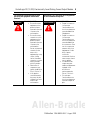
Throughout this manual we use notes to make you aware of safety considerations.
!
WARNING
Identifies information about practices or circumstances that can cause an
explosion in a hazardous environment, which may lead to personal injury or
death, property damage, or economic loss.
ATTENTION
!
Identifies information about practices or circumstances that can lead to personal
injury or death, property damage, or economic loss. Attentions help you:
• identify a hazard
• avoid a hazard
• recognize the consequence
IMPORTANT
Identifies information that is critical for successful application and
understanding of the product.
SHOCK HAZARD
Labels may be located on or inside the drive to alert people that dangerous
voltage may be present.

ControlLogix DC (10-30V) Electronically-Fused Sinking Current Output Module 3
Publication
1756-IN582A-EN-P - August 2003
Environment and Enclosure
Prevent Electrostatic Discharge
ATTENTION
!
This equipment is intended for use in a Pollution Degree 2 industrial
environment, in overvoltage Category II applications (as defined in IEC
publication 60664-1), at altitudes up to 2000 meters without derating.
This equipment is considered Group 1, Class A industrial equipment
according to IEC/CISPR Publication 11. Without appropriate precautions,
there may be potential difficulties ensuring electromagnetic compatibility in
other environments due to conducted as well as radiated disturbance.
This equipment is supplied as "open type" equipment. It must be mounted
within an enclosure that is suitably designed for those specific
environmental conditions that will be present and appropriately designed to
prevent personal injury resulting from accessibility to live parts. The interior
of the enclosure must be accessible only by the use of a tool. Subsequent
sections of this publication may contain additional information regarding
specific enclosure type ratings that are required to comply with certain
product safety certifications.
NOTE: See NEMA Standards publication 250 and IEC publication 60529, as
applicable, for explanations of the degrees of protection provided by
different types of enclosure. Also, see the appropriate sections in this
publication, as well as the Allen-Bradley publication 1770-4.1 ("Industrial
Automation Wiring and Grounding Guidelines"), for additional installation
requirements pertaining to this equipment.
ATTENTION
!
This equipment is sensitive to electrostatic discharge, which can cause
internal damage and affect normal operation. Follow these guidelines when
you handle this equipment:
• Touch a grounded object to discharge potential static.
• Wear an approved grounding wriststrap.
• Do not touch connectors or pins on component boards.
• Do not touch circuit components inside the equipment.
• If available, use a static-safe workstation.
When not in use, store the equipment in appropriate static-safe packaging.
Allen-Bradley Parts

4 ControlLogix DC (10-30V) Electronically-Fused Sinking Current Output Module
Publication
1756-IN582A-EN-P - August 2003
Removal and Insertion Under Power
Be sure that power is removed or the area is nonhazardous before
proceeding. Repeated electrical arcing causes excessive wear to
contacts on both the module and its mating connector. Worn contacts
may create electrical resistance that can affect module operation.
North American Hazardous Location Approval
!
WARNING
When you insert or remove the module while backplane
power is on, an electrical arc can occur. This could cause
an explosion in hazardous location installations.
The following information applies when
operating this equipment in hazardous
locations:
Informations sur l’utilisation de cet équipement
en environnements dangereux :
Products marked “CL I, DIV 2, GP A, B, C, D” are
suitable for use in Class I Division 2 Groups A, B,
C, D, Hazardous Locations and nonhazardous
locations only. Each product is supplied with
markings on the rating nameplate indicating the
hazardous location temperature code. When
combining products within a system, the most
adverse temperature code (lowest “T” number)
may be used to help determine the overall
temperature code of the system. Combinations
of equipment in your system are subject to
investigation by the local Authority Having
Jurisdiction at the time of installation.
Les produits marqués "CL I, DIV 2, GP A, B, C, D" ne
conviennent qu’à une utilisation en environnements de
Classe I Division 2 Groupes A, B, C, D dangereux et
non dangereux. Chaque produit est livré avec des
marquages sur sa plaque d’identification qui indiquent
le code de température pour les environnements
dangereux. Lorsque plusieurs produits sont combinés
dans un système, le code de température le plus
défavorable (code de température le plus faible) peut
être utilisé pour déterminer le code de température
global du système. Les combinaisons d’équipements
dans le système sont sujettes à inspection par les
autorités locales qualifiées au moment de
l’installation.

ControlLogix DC (10-30V) Electronically-Fused Sinking Current Output Module 5
Publication
1756-IN582A-EN-P - August 2003
!
WARNING
EXPLOSION HAZARD
• Do not disconnect
equipment unless
power has been
removed or the area
is known to be
nonhazardous.
• Do not disconnect
connections to this
equipment unless
power has been
removed or the area
is known to be
nonhazardous.
Secure any external
connections that
mate to this
equipment by using
screws, sliding
latches, threaded
connectors, or other
means provided
with this product.
• Substitution of
components may
impair suitability for
Class I, Division 2.
• If this product
contains batteries,
they must only be
changed in an area
known to be
nonhazardous.
AVERTISSEMENT
!
RISQUE D’EXPLOSION
• Couper le courant ou
s’assurer que
l’environnement est
classé non dangereux
avant de débrancher
l'équipement.
• Couper le courant ou
s'assurer que
l’environnement est
classé non dangereux
avant de débrancher
les connecteurs. Fixer
tous les connecteurs
externes reliés à cet
équipement à l'aide
de vis, loquets
coulissants,
connecteurs filetés ou
autres moyens fournis
avec ce produit.
• La substitution de
composants peut
rendre cet équipement
inadapté à une
utilisation en
environnement de
Classe I, Division 2.
• S’assurer que
l’environnement est
classé non dangereux
avant de changer les
piles.
The following information applies when
operating this equipment in hazardous
locations:
Informations sur l’utilisation de cet équipement
en environnements dangereux :
Allen-Bradley Parts

6 ControlLogix DC (10-30V) Electronically-Fused Sinking Current Output Module
Publication
1756-IN582A-EN-P - August 2003
Identify the Module Components
You received the following components with your order:
• 1756-OV32E module
• Removable Terminal Block (RTB) door label
If you did not receive these components, contact your local
distributor Rockwell Automation sales office.
This module mounts in a 1756 chassis and uses a separately-ordered
RTB or a Bulletin 1492 Interface Module (IFM)
(1)
to connect all
field-side wiring. This module uses one of the following RTBs:
• 1756-TBCH 36-position Cage clamp RTB
• 1756-TBS6H 36-position Spring clamp RTB
Use an extended-depth cover (1756-TBE) for applications with heavy
gauge wiring or requiring additional routing space. When using an
IFM, consult the documentation that came with it to connect wiring.
Note the Power Requirements
This module receives power from the 1756 chassis power supply and
requires 2 sources of power from the ControlLogix backplane:
• 390mA at 5.1V dc
• 2mA at 24V dc
Add this current/power value (2.04W) to the requirements of all other
modules in the chassis to prevent overloading the power supply.
(1)
The Bulletin 1492 IFM may not be used in any application that requires agency certification of the
ControlLogix
®
system. Use of the IFM violates the UL, CSA and FM certifications of this product.
IMPORTANT
Before you install your module, you should:
• install and ground a 1756 chassis and power supply.
• order and receive an RTB or IFM, and its
components, for your application.

ControlLogix DC (10-30V) Electronically-Fused Sinking Current Output Module 7
Publication
1756-IN582A-EN-P - August 2003
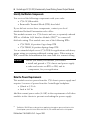
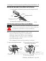
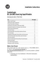
Install the Module
You can install or remove the module while chassis power is applied.
Be sure that power is removed or the area is nonhazardous before
proceeding. Repeated electrical arcing causes excessive wear to
contacts on both the module and its mating connector. Worn contacts
may create electrical resistance that can affect module operation.
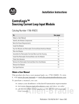
1. Align the circuit board with the top and bottom chassis guides.
2. Slide the module into chassis until module locking tabs click.
!
WARNING
When you insert or remove the module while backplane
power is on, an electrical arc can occur. This could cause
an explosion in hazardous location installations.
20861–M
Printed
Circuit
Board
Locking tab
Allen-Bradley Parts

8 ControlLogix DC (10-30V) Electronically-Fused Sinking Current Output Module
Publication
1756-IN582A-EN-P - August 2003
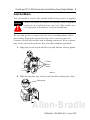
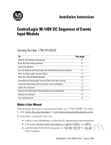
Key the Module and Removable Terminal Block/Interface Module
Use the wedge-shaped keying tabs and U-shaped keying bands to
prevent connecting the wrong wires to your module.
Key positions on the module that correspond to unkeyed positions
on the RTB. For example, if you key the first position on the module,
leave the first position on the RTB unkeyed.
1. To key the module, insert the U-shaped band, as shown.
2. Push the band until it snaps in place.
3. To key the RTB or IFM, insert the wedge-shaped tab with
rounded edge first, as shown.
4. Push the tab until it stops.
Reposition the tabs to rekey future module applications.
20850–M
U-shaped
bands
20851–M
Wedge-shaped tab

ControlLogix DC (10-30V) Electronically-Fused Sinking Current Output Module 9
Publication
1756-IN582A-EN-P - August 2003
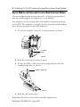
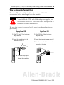
Wire the Removable Terminal Block
Wire the RTB with a 1/8 inch (3.2mm) maximum flat-bladed
screwdriver before installing it onto the module.
Be sure that power is removed or the area is nonhazardous before
proceeding.
!
WARNING
When you connect or disconnect the Removable
Terminal Block (RTB) with field side power applied, an
electrical arc can occur. This could cause an explosion in
hazardous location installations.
Spring Clamp RTB Cage Clamp RTB
20860-M
20859-M
1. Strip 7/16 inch (11mm) maximum
length of wire.
2. Insert the screwdriver into the
inner hole of the RTB.
3. Insert the wire into the
open terminal and
remove the screwdriver.
1. Strip 3/8 inch (9.5mm) maximum
length of wire.
2. Insert the wire into the open terminal.
3. Turn the screw clockwise to close the
terminal on the wire.
Allen-Bradley Parts

10 ControlLogix DC (10-30V) Electronically-Fused Sinking Current Output Module
Publication
1756-IN582A-EN-P - August 2003
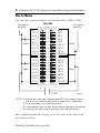
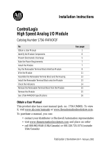
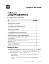
Wire the Module
You can only connect wiring to your module with an RTB or IFM.
After completing field-side wiring, secure the wires in the strain relief
area with a cable-tie.
43386-M
12
34
56
78
910
1112
1314
1516
1718
1920
2122
2324
2526
2728
2930
3132
3334
3536
+
_
Daisy chain to
other RTBs
Daisy chain to
other RTBs
1. When you daisy chain from a group to another RTB, always connect the daisy
chain to the terminal directly connected to the supply wire, as shown above.
2. This wiring example uses a single voltage source.
3. If separate power sources are used, do not exceed the specified isolation voltag
e
4. Do not physically connect more than two wires to a single RTB terminal.
Group 0
Group 1
Group 0
Group 1
DC COM
OUT-1
OUT-3
OUT-5
OUT-7
OUT-9
OUT-11
OUT-13
OUT-15
DC-0(+)
DC-1(+)
OUT-0
OUT-2
OUT-4
OUT-6
OUT-8
OUT-10
OUT-12
OUT-14
RTN OUT-0
RTN OUT-1
OUT-17
OUT-19
OUT-21
OUT-23
OUT-25
OUT-27
OUT-29
OUT-31
OUT-16
OUT-18
OUT-20
OUT-22
OUT-24
OUT-26
OUT-28
OUT-30
1756-OV32E
NOTES:

ControlLogix DC (10-30V) Electronically-Fused Sinking Current Output Module 11
Publication
1756-IN582A-EN-P - August 2003
Assemble the Removable Terminal Block and the Housing
Install the Removable Terminal Block onto the Module
Before proceeding with RTB installation, make certain:
• power is removed or the area is nonhazardous.
• field-side wiring of the RTB has been completed.
• the RTB housing is snapped in place on the RTB.
• the RTB housing is closed.
• the locking tab at the top of the module is unlocked.
!
WARNING
If you connect or disconnect wiring while the field-side
power is on, an electrical arc can occur. This could cause
an explosion in hazardous location installations.
20852-M
Groove
Groove
Side edge of the RTB
Side edge of the RTB
1. Align the grooves at the bottom of the housing with the side edges of the RTB.
2. Slide the RTB into the housing until it snaps into place.
20853–M 20854–M
Module
guide
RTB guides
Locking tab
1. Align the side and top, bottom guides. 2. Press quickly and evenly to seat the RTB
until the latches snap into place.
3. Slide the locking tab down.
Allen-Bradley Parts

12 ControlLogix DC (10-30V) Electronically-Fused Sinking Current Output Module
Publication
1756-IN582A-EN-P - August 2003
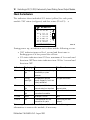
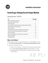
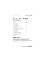
Check the Indicators
The indicators show individual I/O status (yellow) for each point,
module "OK" status (red/green) and fuse status (F0 & F1). x
During power up, an indicator test is done and the following occurs:
• "OK" indicator turns red for 1 second and then turns to
flashing green if it has passed the self-test.
• I/O status indicators turn ON for a maximum of 2 seconds and
then turn OFF.Fuse status indicators turn ON for 1 second and
then turn OFF.
This completes installation of the module. Use the following
information to remove the module, if necessary.
Indicator: Displaying: Means: Take this action:
OK Steady green
light
The outputs are actively being
controlled by a system
processor.
None
OK Flashing
green light
The module has passed
internal diagnostics but is not
actively controlled.
Configure the module.
OK Flashing red
light
Previously established
communication has timed out.
Check controller and chassis
communication.
OK Steady red
light
An unrecoverable error has
occurred on the module.
Replace the module.
I/O State Yellow The output is active. None
I/O Fuse Red A short overload fault has
occurred for this point.
Check wiring for short
overload.
O
K
ST 012 34567
ST 8 9
1
021345
11 1 11
ST
67
1
809123
12 2 2211
ST
45
2
687901
22 2 3322
40465-M
DC OUTPUT
ELECTRONIC FUSING
F
0
F
1

ControlLogix DC (10-30V) Electronically-Fused Sinking Current Output Module 13
Publication
1756-IN582A-EN-P - August 2003
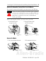
Remove the Removable Terminal Block from the Module
If you need to remove the module, you must remove the RTB first.
Before removing the module, you must remove the RTB.
Remove the Module
!
WARNING
When you insert or remove the module while backplane
power is on, an electrical arc can occur. This could cause
an explosion in hazardous location installations. Be sure
that power is removed or the area is nonhazardous
before proceeding.
20855–M
2. Open the RTB door and pull
the RTB off the module.
1. Unlock the locking tab at
the top of the module.
42517
1. Push in top and bottom locking tabs. 2. Pull module out of the chassis.
20856–M 20857–M
Allen-Bradley Parts

14 ControlLogix DC (10-30V) Electronically-Fused Sinking Current Output Module
Publication
1756-IN582A-EN-P - August 2003
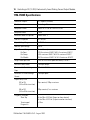
1756-OV32E
Specifications
Number of Outputs 32 (16 points/common)
Module Location ControlLogix Chassis
Backplane Current 390mA @ 5.1V dc & 2.0mA @ 24V dc
Backplane Power 2.04W
Maximum Power Dissipation 5.88W @ 60° C
Thermal Dissipation 20.1 BTU/hr
Output Voltage Range 10-30.0 V dc
Nominal Input Voltage 24V dc
Output Current Rating
Per Point
Per Group
Per Module
Derated linearly
0.35 A maximum @ 60°C & 0.5 A maximum @ 50°C
5.0 A maximum @ 60°C & 8.0 A maximum @ 50°C
10.0 A maximum @ 60°C & 16.0 A maximum @ 50°C
Surge Current per Point 2.0 A for 10ms each repeatable every2s @ 60°C
Minimum Load Current 2.0mA per output
Maximum On-State Voltage
Drop
350mV dc @ 0.5A
Maximum Off-State Leakage
Current
1.0mA per point
Output Delay Time
OFF to ON
(24V to 0V dc transition)
ON to OFF
(24V to 0V dc transition)
75
µs nominal; 300µs maximum
230
µs nominal; 1ms maximum
Diagnostic Functions
Short Trip
Timestamp of
Diagnostics
5A for 20ms @ 24Vdc (Output on then shorted)
5A for 20ms @ 24V dc (Output turned on into short)
± 1.0ms

ControlLogix DC (10-30V) Electronically-Fused Sinking Current Output Module 15
Publication
1756-IN582A-EN-P - August 2003
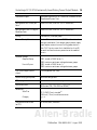
Scheduled Outputs Synchronization within 16.7s maximum, reference to the
Coordinated System Time
Configurable Fault States per
Point
Hold Last State, ON or OFF (OFF is the default)
Configurable States in Program
Mode per Point
Hold Last State, ON or OFF (OFF is the default)
Fusing Electronically fused per group
Reverse Polarity Protection Yes for 60 seconds maximum @ 60 C° without circuit
damage (conditional). Each output group’s power supply
input requires external current limiting protection less
than 15A. Time to current limit should be less than 60
seconds to afford maximum protection to the module’s
circuits.
Isolation Voltage
Group to Group
User to System
100% tested at 2546V dc for 1s
250V maximum continuous voltage between groups
100% tested at 2546V dc for 1s
250V maximum continuous voltage between groups
RTB Screw Torque (NEMA
clamp)
7-9 inch-pounds (0.8-1Nm)
Module Keying (Backplane) Software configurable
RTB Keying User defined mechanical keying
Field Wiring Arm
36 Position RTB (1756-TBCH or TBS6H)
(1)
Conductors
Wire Size
Category
22-14 AWG (2mm) stranded
(2)
3/64-inch (1.2mm) insulation maximum
1
(2)
,
(3)
Screwdriver Blade Width
for RTB
5/16-inch (8mm) maximum
Allen-Bradley Parts

16 ControlLogix DC (10-30V) Electronically-Fused Sinking Current Output Module
Publication
1756-IN582A-EN-P - August 2003
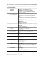
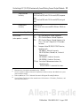
Environmental Conditions
Operational
Temperature
IEC 60068-2-1 (Test Ad, Operating Cold),
IEC 60068-2-2 (Test Bd, Operating Dry Heat),
IEC 60068-2-14 (Test Nb, Operating Thermal Shock):
0 to 60°C (32 to 140°F)
Storage Temperature
IEC 60068-2-1 (Test Ab, Un-packaged Non-operating
Cold),
IEC 60068-2-2 (Test Bb, Un-packaged Non-operating Dry
Heat),
IEC 60068-2-14 (Test Na, Un-packaged Non-operating
Thermal Shock):
-40 to 85°C (-40 to 185°F)
Relative Humidity IEC 60068-2-30 (Test Db, Un-packaged Non-operating
Damp Heat):
5 to 95% non-condensing
Vibration IEC 60068-2-6 (Test Fc, Operating):
2g @ 10-500Hz
Operating Shock IEC 60068-2-27 (Test Ea, Unpackaged Shock):
30g
Non-operating Shock IEC 60068-2-27 (Test Ea, Unpackaged Shock):
50g
Emissions CISPR 11:
Group 1, Class A
ESD Immunity IEC 61000-4-2:
6kV contact discharges
8kV air discharges
Radiated RF Immunity IEC 61000-4-3:
20V/m with 1kHz sine-wave 80%AM from 80MHz to
1000MHz
EFT/B Immunity IEC 61000-4-4:
±4kV at 2.5kHz on power ports
±4kV at 2.5kHz on signal ports

ControlLogix DC (10-30V) Electronically-Fused Sinking Current Output Module 17
Publication
1756-IN582A-EN-P - August 2003
Surge Transient
Immunity
IEC 61000-4-5:
±1kV line-line(DM) and ±2kV line-earth(CM) on power
ports
±1kV line-line(DM) and ±2kV line-earth(CM) on signal
ports
Conducted RF
Immunity
IEC 61000-4-6:
10Vrms with 1kHz sine-wave 80%AM from 150kHz to
80MHz
Enclosure Type Rating None (open-style)
Certifications:
(when product is marked)
UL UL Listed Industrial Control Equipment
CSA CSA Certified Process Control Equipment
CSA CSA Certified Process Control Equipment for
Class I, Division 2 Group A,B,C,D Hazardous
Locations
CE
(4)
European Union 89/336/EEC EMC Directive,
compliant with:
EN 50082-2; Industrial Immunity
EN 61326; Meas./Control/Lab., Industrial
Requirements
EN 61000-6-2; Industrial Immunity
EN 61000-6-4; Industrial Emissions
C-Tick
(4)
Australian Radiocommunications Act,
compliant with:
AS/NZS CISPR 11; Industrial Emissions
(1)
Maximum wire size requires extended housing - 1756-TBE.
(2)
Use this conductor category information for planning conductor routing as described in the system
level installation manual.
(3)
Refer to publication 1770-4.1 Industrial Automation Wiring and Grounding Guidelines.
(4)
See the Product Certification link at www.ab.com for Declarations of Conformity, Certificates, and
other certification details.
Allen-Bradley Parts

18 ControlLogix DC (10-30V) Electronically-Fused Sinking Current Output Module
Publication
1756-IN582A-EN-P - August 2003
Notes:

ControlLogix DC (10-30V) Electronically-Fused Sinking Current Output Module 19
Publication
1756-IN582A-EN-P - August 2003
Notes:
Allen-Bradley Parts

Publication 1756-IN582A-EN-P - August 2003 PN 957707-74
Copyright © 2003 Rockwell Automation, Inc. All rights reserved. Printed in the U.S.A.
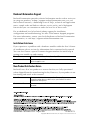
Rockwell Automation Support
Rockwell Automation provides technical information on the web to assist you
in using our products. At http://support.rockwellautomation.com, you can
find technical manuals, a knowledge base of FAQs, technical and application
notes, sample code and links to software service packs, and a MySupport
feature that you can customize to make the best use of these tools.
For an additional level of technical phone support for installation,
configuration and troubleshooting, we offer TechConnect Support programs.
For more information, contact your local distributor or Rockwell Automation
representative, or visit http://support.rockwellautomation.com.
Installation Assistance
If you experience a problem with a hardware module within the first 24 hours
of installation, please review the information that's contained in this manual.
You can also contact a special Customer Support number for initial help in
getting your module up and running:
New Product Satisfaction Return
Rockwell tests all of our products to ensure that they are fully operational
when shipped from the manufacturing facility. However, if your product is not
functioning and needs to be returned:
United States 1.440.646.3223 Monday – Friday, 8am – 5pm EST
Outside United States Please contact your local Rockwell Automation representative for any
technical support issues.
United States Contact your distributor. You must provide a Customer Support case number
(see phone number above to obtain one) to your distributor in order to
complete the return process.
Outside United States Please contact your local Rockwell Automation representative for return
procedure.
-
 1
1
-
 2
2
-
 3
3
-
 4
4
-
 5
5
-
 6
6
-
 7
7
-
 8
8
-
 9
9
-
 10
10
-
 11
11
-
 12
12
-
 13
13
-
 14
14
-
 15
15
-
 16
16
-
 17
17
-
 18
18
-
 19
19
-
 20
20


Allen-Bradley ControlLogix 1756-OV32E Installation Instructions Manual
- Taper
- Installation Instructions Manual
dans d''autres langues
Documents connexes
-
 Allen-Bradley ControlLogix 1756-OX8I Installation Instructions Manual
-
 Allen-Bradley ControlLogix 1756-IF6CIS Installation Instructions Manual
-
 Allen-Bradley ControlLogix 1756-IF4FXOF2F Installation Instructions Manual
-
Allen-Bradley ControlLogix 1756-IC16 Installation Instructions Manual
-
 Allen-Bradley ControlLogix 1756-OF4 Installation Instructions Manual
-
Allen-Bradley 1756-OV16E Installation Instructions Manual
-
 Allen-Bradley ControlLogix 1756-IB16D Installation Instructions Manual
-
 Allen-Bradley ControlLogix 1756-IH16ISOE Installation Instructions Manual
-
 Allen-Bradley ControlLogix 1756-OF6VI Installation Instructions Manual
-
 Allen-Bradley ControlLogix 1756-EN2F Installation Instructions Manual


