
Refrigerated Drawers
Tiroirs réfrigérés
MP24RDS3**
MP24RDP3**
EN Installation, Operation and Maintenance Instructions
FR Instructions d’installation, d’utilisation et d’entretien

2
NOTE
!
CAUTION
Contents:
Safety information ...............................................................2
Unpacking your appliance ..................................................3
Warranty registration .....................................................3
Installing your appliance ......................................................4
Cabinet clearances .........................................................4
Leveling the appliance ....................................................4
Electrical connection ......................................................5
Installing the anti-tip device .................................................6
Drawer divider .....................................................................7
Product dimensions ............................................................8
Using your Electronic control ............................................10
Starting your appliance ..................................................10
Sleep mode ...................................................................10
Turning your appliance "ON" or "OFF" ..........................10
Adjusting the temperature .............................................11
Temperature mode ........................................................11
Control lock ....................................................................11
Temperature sensor error codes ....................................11
Alarms ...........................................................................12
Door (drawer) ajar.....................................................12
Power failure ............................................................12
Temperature alarm ...................................................12
Interior lighting ...............................................................12
Vacation mode ................................................................13
Overlay drawer panel installation .....................................13
Care and cleaning .............................................................16
Energy saving tips ............................................................17
Obtaining service .............................................................17
Troubleshooting ................................................................18
Warranty ...........................................................................19
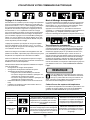
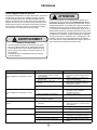
Important Safety Instructions
Warnings and safety instructions appearing in this guide
are not meant to cover all possible conditions and situa-
tions that may occur. Common sense, caution, and care
must be exercised when installing, maintaining, or operat-
ing this appliance.
Recognize Safety Symbols,
Words, and Labels.
CAUTION-Hazards or unsafe practices which could re-
sult in personal injury or property / product damage.
NOTE-Important information to help assure a problem
free installation and operation.
CONTENTS
!
WARNING
WARNING - You can be killed or seriously injured
if you do not follow these instructions.
!
WARNING
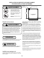
State of California Proposition 65 Warning:
This product contains one or more chemicals known
to the State of California to cause cancer.
!
WARNING
State of California Proposition 65 Warning:
This product contains one or more chemicals known
to the State of California to cause birth defects or
other reproductive harm..

3
NOTE
!
CAUTION
!
WARNING
XXXXXXXXXXXX
XXXXXXXXXXXX
MARVEL
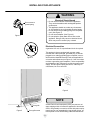
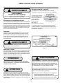
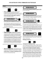
UNPACKING YOUR APPLIANCE
EXCESSIVE WEIGHT HAZARD
Use two or more people to move product.
Failure to do so can result in personal injury.
Remove Interior Packaging
Your appliance has been packed for shipment with all parts
that could be damaged by movement securely fastened.
Remove internal packing materials and any tape holding in-
ternal components in place. The owners manual is shipped
inside the product in a plastic bag along with the warranty
registration card, and other accessory items.
Important
Keep your carton and packaging until your appliance has
been thoroughly inspected and found to be in good condi-
tion. If there is damage, the packaging will be needed as
proof of damage in transit. Afterwards please dispose of all
items responsibly.
Note to Customer
This merchandise was carefully packed and thoroughly
inspected before leaving our plant. Responsibility for its
safe delivery was assumed by the retailer upon acceptance
of the shipment. Claims for loss or damage sustained in
transit must be made to the retailer.
DO NOT RETURN DAMAGED MERCHANDISE TO THE
MANUFACTURER - FILE THE CLAIM WITH THE
RETAILER.
If the appliance was shipped, handled, or stored in other
than an upright position for any period of time, allow the ap-
pliance to sit upright for a period of at least 24 hours before
plugging in. This will assure oil returns to the compressor.
Plugging the appliance in immediately may cause damage
to internal parts.
It is important you send in your warranty registration card
immediately after taking delivery of your appliance or you
can register online at www.marvelrefrigeration.com.
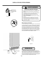
The following information will
be required when registering
your appliance.
Service Number
Rev. Letter
Serial Number
Date of Purchase
Dealer’s name and address
The service number and serial number can be found on
the serial plate which is located inside the cabinet on the
bottom of the liner toward the left side. Open the bottom
drawer to view it. See gure 1.
Warranty Registration
Online registra-
tion available at
www.marvelrefrig-
eration.com
Figure 1
!
WARNING
WARNING - Help Prevent Tragedies
Child entrapment and suffocation are not problems of
the past. Junked or abandoned refrigerators are still
dangerous - even if they sit out for "just a few hours".
If you are getting rid of your old refrigerator, please
follow the instructions below to help prevent acci-
dents.
Before you throw away your old refrigerator or
freezer:
• Take off the doors or remove the drawers.
• Leave the shelves in place so children may not
easily climb inside.
!
WARNING
WARNING - Dispose of the plastic bags which can
be a suffocation hazard.

4
!
CAUTION
!
WARNING
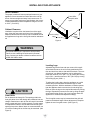
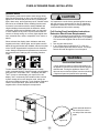
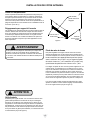
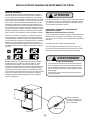
Figure 2
Front Leveling
Legs
Front Grille,
keep this area
open.
Rear
Leveling
Legs
Select Location
The proper location will ensure peak performance of your
appliance. We recommend a location where the unit will
be out of direct sunlight and away from heat sources. To
ensure your product performs to specications, the recom-
mended installation location temperature range is from 55
to 100°F (13 to 38°C).
Cabinet Clearance
Ventilation is required from the bottom front of the appli-
ance. Keep this area open and clear of any obstructions.
Adjacent cabinets and counter top can be installed around
the appliance as long as the front grille remains unobstruct-
ed.
Front Grille
Do not obstruct the front grille. The openings within the
front grille allow air to ow through the condenser heat ex-
changer. Restrictions to this air ow will result in increased
energy usage and loss of cooling capacity. For this reason
it is important this area to not be obstructed and the grille
openings kept clean. Marvel does not recommend the use
of a custom made grille as air ow may be restricted. (See
Figure 2).
Leveling Legs
Adjustable legs at the front and rear corners of the appli-
ance should be set so the unit is rmly positioned on the
oor and level from side to side and front to back. The over-
all height of your Marvel appliance may be adjusted be-
tween the minimum, 33
3
⁄4" (85.7 cm), by turning the leveling
leg in (CW ↷) and the maximum, 34
3
⁄4" (88.3 cm) by turning
the leveling leg out (CCW ↶).
To adjust the leveling legs, place the appliance on a solid
surface and protect the oor beneath the legs to avoid
scratching the oor. With the assistance of another person,
lean the appliance back to access the front leveling legs.
Raise or lower the legs to the required dimension by turning
the legs. Repeat this process for the rear by tilting the appli-
ance forward using caution. On a level surface check the
appliance for levelness and adjust accordingly.
The front grille screws may be loosened and the grille ad-
justed to the desired height. When adjustment is complete
tighten the two front grille screws. (See Figure 5).
INSTALLING YOUR APPLIANCE
An optional stacking kit is required to stack products.
Failure to use a stacking kit could result in personal
injury. Contact your dealer or Marvel customer service
at 800-223-3900 to order.

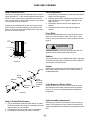
5
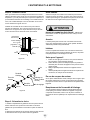
NOTE
Electrical Shock Hazard
• Do not use an extension cord with this appliance.
They can be hazardous and can degrade product
performance.
• This appliance should not, under any circumstanc-
es, be installed to an un-grounded electrical supply.
• Do not remove the grounding prong from the power
cord. (See Figure 3).
• Do not use an adapter. (See Figure 4).
• Do not splash or spray water from a hose on the
appliance. Doing so may cause an electrical shock,
which may result in severe injury or death.
!
WARNING
Ground Fault Circuit Interrupters (GFCI) are prone to nui-
sance tripping which will cause the appliance to shut down.
GFCI’s are generally not used on circuits with power equip-
ment that must run unattended for long periods of time, un-
less required to meet local building codes and ordinances.
Electrical Connection
A grounded 115 volt, 15 amp dedicated circuit is required.
This product is factory equipped with a power supply
cord that has a three-pronged, grounded plug. It must be
plugged into a mating grounding type receptacle in accor-
dance with the National Electrical Code and applicable lo-
cal codes and ordinances (see Figure 6). If the circuit does
not have a grounding type receptacle, it is the responsibility
and obligation of the customer to provide the proper power
supply. The third ground prong should not, under any cir-
cumstances, be cut or removed.
Figure 6
Figure 5
Front grille screw
Front grille
INSTALLING YOUR APPLIANCE
Figure 3
Figure 4
Do not remove
ground prong

6
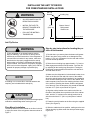
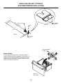
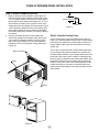
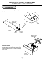
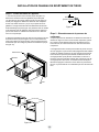
INSTALLING THE ANTI TIP DEVICE
FOR FREESTANDING INSTALLATIONS
Step by step instructions for locating the po-
sition of the bracket:
1) Decide where you want to place the drawer refrigerator.
Slide it into place, being careful not to damage the oor,
leaving 1" (2.5 cm) of clearance from the rear wall to allow
room for the anti-tip bracket.
2) Raise the rear leveling legs approximately
1
⁄4" (6 mm) to
allow engagement with the anti-tip bracket. Level the unit
by adjusting all the leveling legs as required. Turning the
leveling leg counterclockwise will raise the unit and clock-
wise will lower the unit.
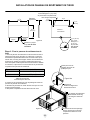
3) Make sure the refrigerator is in the desired location, then
mark on the oor the rear and side corner of the cabinet
where the anti-tip bracket will be installed. If the installation
does not allow marking the rear corner of the cabinet, then
make temporary lines on the oor marking the front corner
of the cabinet, excluding the drawer. Slide the refrigerator
out of the way. From the temporary line extend the sidewall
line back 21
1
⁄2" (54.6 cm) as shown in Figure 8.
4) Align the anti-tip bracket to the marks on the oor so
the side of the bracket lines up with the side of the cabinet
mark, and the "V" notches on the anti-tip bracket line up
with the end of the 21
1
⁄2" (54.6 cm) line (Rear of cabinet
line).
5) Fasten the anti-tip bracket to the oor using the supplied
screw. (See Figure 8).
6) Slide the cabinet back into position, making sure the rear
cabinet leveling leg slides under the anti-tip bracket engag-
ing the slot.
Bottom View of
Refrigerated
Drawer Unit
Anti-Tip
Bracket
Leveling Leg
Front of cabinet
21
1
⁄2"
(54.6 cm)
Figure 7
!
WARNING
• ALL APPLIANCES CAN TIP
RESULTING IN INJURY.
• INSTALL THE ANTI-TIP
BRACKET PACKED WITH
THE APPLIANCE.
• FOLLOW THE INSTRUC-
TIONS BELOW
Floor Mount Installation
The anti-tip bracket is to be located on the oor in the left
or right rear corner of the refrigerator drawer as shown in
Figure 7.
!
CAUTION
NOTE
Any nished ooring should be protected with appropriate
material to avoid damage when moving the unit.
If installing on a concrete oor, concrete fasteners are
required, (not included with the anti-tip kit).
Anti-Tip Device
!
WARNING
If your refrigerator is not located under a counter
top (free standing), you must use an anti-tip device
installed as per these instructions. If the refrigerator is
removed from its location for any reason, make sure
that the device is properly engaged with the anti-tip
bracket when you push the refrigerator back into the
original location. If the device is not properly engaged,
there is a risk of the refrigerator tipping over, with the
potential for property damage or personal injury.

7
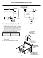
INSTALLING THE ANTI TIP DEVICE
FOR FREESTANDING INSTALLATIONS
21
1
⁄2"
(54.6 cm)
"V" notches
in bracket
"V" notches
in bracket
Figure 8
Rear of cabinet line
Figure 8a
Side of cabinet line
Front of cabinet line
Screw
Rear Leveling leg
Figure 9
Top drawer
Drawer Divider
The top and bottom drawer have an adjustable drawer
divider. To adjust the divider, making the 4 areas larger or
smaller, move the center post along the length of the rods
in either direction. See Figure 9 and 9a. The divider can
also be removed from the drawer.
Move rods within
center post
Figure 9a

8
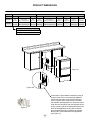
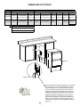
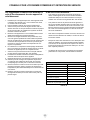
"A"
"B"
"C"
"D"
"E"
ROUGH-IN OPENING DIMENSIONS CABINET DIMENSIONS
MODEL "A" "B" "C" "D" "E" "F" "G" "H" "I"
MP24RDS
24"
(61 cm)
**34" to 35"
(86.4 cm to 88.9 cm)
24"
(61 cm)
23
7
⁄8"
(60.7 cm)
33
3
⁄4" to 34
3
⁄4"
(85.7 cm to 88.3 cm)
23
23
⁄32"
(60.2 cm)
26
7
⁄32"
(66.6 cm)
39
5
⁄32"
(99.5 cm)
41
21
⁄32"
(105.8 cm)
MP24RDP
24"
(61 cm)
**34" to 35"
(86.4 cm to 88.9 cm)
* 24"
(61 cm)
23
7
⁄8"
(60.7 cm)
33
3
⁄4" to 34
3
⁄4"
(85.7 cm to 88.3 cm)
22
7
⁄8"
(58.1 cm)
-
38
5
⁄16"
(97.3 cm)
41
21
⁄32"
(105.8 cm)
DRAWER STYLE
(S) Solid Drawer
(P) Solid Overlay Drawer (no handle)
Figure 10
Figure 10a
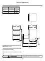
PRODUCT DIMENSIONS
Figure 11
If necessary to gain clearance inside the rough-in
opening a hole can be cut through the adjacent
cabinet and the power cord routed through this
hole to a power outlet. Another way to increase
the available opening depth is to recess the power
outlet into the rear wall to gain the thickness of the
power cord plug. Not all recessed outlet boxes will
work for this application as they are too narrow,
but a recessed outlet box equivalent to Arlington
#DVFR1W is recommended for this application,
(see Figure 11).

9
"D"
"E"
"F"
"G"
"H"
"I"
Floor mount anti-tip bracket.
PRODUCT DATA
MODEL
ELECTRICAL
REQUIREMENTS #
PRODUCT
WEIGHT
MP24RDS 115V/60Hz/15A
130 lbs
(59 kg)
MP24RDP 115V/60Hz/15A
130 lbs
(59 kg)
21
1
⁄2"
(54.6 cm)
1"
(2.5 cm)
!
WARNING
Floor mount Anti-tip Bracket must be installed for freestand-
ing applications. Not required for built in applications.
Figure 12
* To install (P) models with the door face ush with adja-
cent cabinetry doors, custom decorative panel thickness
cannot exceed
3
⁄4" (19 mm).
** Minimum rough-in opening required is to be larger than
the adjusted height of the cabinet.
# A grounded 15 amp dedicated circuit is required. Follow
all local building codes when installing electrical and appli-
ance.
PRODUCT DIMENSIONS

10
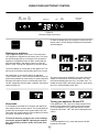
Power Failure
ALARM RESET
Temp
Minus
keypad
Temp
Plus
keypad
On/Off
keypad
Display Area
Lock
keypad
Light
System Status
indicators
Figure 13
Electronic single zone control
Starting your appliance:
Plug the appliance power cord into a 115 volt wall outlet.
Your appliance is shipped from the factory in the "On" posi-
tion and will begin start-up of cooling as soon as power is
supplied. If the appliance does not start, conrm that the
wall outlet has power, and that the control is in the "On"
position, (See "Turning your appliance On and Off" below).
The control display is covered with a clear plastic lm. This
lm may be removed by carefully lifting the lm at a corner.
On initial power up, the control display will indicate a
"Power Failure" alarm. This is a normal condition as the ap-
pliance was powered-up at the factory for quality inspection
and then removed from power. A momentary press of the
"On/Off" keypad will reset this alarm condition. (See Alarms
section on page 12).
Turning your appliance ON and OFF:
If the appliance is "On", (and out of sleep mode) the tem-
perature will be shown in the display area of the control.
To turn the appliance "Off", press and hold the "On/Off"
keypad for 4-seconds. "OFF" will now be displayed on the
control.
To turn the appliance "On", press and hold the "On/Off"
keypad for 4-seconds.
Sleep mode:
If no keypads are pressed for 60 seconds, the display will
enter sleep mode to conserve power. The control panel will
go dark with the exception of the system status "OK" indi-
cator which will remain enabled. Alarm conditions will wake
the display, (see alarms on page 12).
To make the following changes to the control settings
(turning the appliance ON/OFF, adjusting the tempera-
ture, and activating vacation mode), the control must
be awake.
The sleep mode can be disabled if you prefer to have the
display on continuously. Press and hold the "Lock" key-
pad until the display goes past "Loc" and reads "nSL". To
enable the sleep mode, repeat the instruction, again going
past "Loc" until the display reads "SLP".
To wake the display press any keypad. A conrm tone will
sound, and the current storage compartment temperature
will be displayed.
USING YOUR ELECTRONIC CONTROL

11
Temperature Sensor Error Codes
Sensor Displayed Code Error Description Action to Take
Single Zone
Temperature
Sensor
Failed temperature sensor in the single zone
compartment. Can lead to
unwanted storage temperatures and/or
spoiled perishable goods.
Call service to have the
temperature sensor replaced and
remove all perishable goods from
compartment to prevent spoilage.
Defrost Sensor
Failed defrost temperature sensor.
Causes unit to not defrost properly and can
create large frost build-up. Can lead to water
damage to the unit and
surrounding oor.
Unplug the power cord
immediately and call service to
have the defrost sensor replaced.
The temperature sensors are monitored continuously. Any
OPEN or SHORTED circuit condition will initiate an ER-
ROR CODE as listed below:
Temperature Sensor Error Codes
Temperature mode:
The temperature mode is preset from the factory in Fahren-
heit (°F) but you have the option to change it to Centigrade
(°C). To change the mode, press and hold the "-" keypad,
while pressing the "+" keypad, then release the "-" keypad.
The temperature will now be displayed in Centigrade (°C).
Repeat the procedure to change the temperature mode
back to Fahrenheit (°F).
Control lock:
The control panel can be locked to avoid unintentional
changes. To lock the control, press and hold the "Lock" key-
pad until the display reads "Loc" then immediately release
your nger from the keypad. The lock icon will ash 3-times
and then continuously illuminate. When the control panel is
locked, only the Lock keypad, System Status OK indicator
, and the Alarm indicator are active. To un-lock the control
panel, repeat this instruction until the display reads "nLc"
then immediately release your nger from the keypad.
Adjusting the temperature:
To set or check the set-point temperature (with the control
out of sleep mode), press the "-" or "+" keypads. "SET" will
be indicated on the user interface panel and the current
set-point temperature will display and ash. Subsequent
presses of the "-" or "+" keypads will adjust the temperature
colder or warmer respectively. When you have reached
your desired set-point temperature, press the "On/Off" key-
pad to accept, or do nothing and the "Set" mode will time-
out in 10-seconds accepting the displayed temperature as
the new set-point.
The available set-point temperature range for your ap-
pliance is 34°F (1.2°C) to 42°F (5.7°C). If you attempt to
adjust the temperature outside of this range you will receive
an audible notication.
When initially loading your product with warm contents, it
may take up to 48-hours for the storage compartment tem-
perature to stabilize.
When making temperature set-point changes, it may take
up to 24-hours for the stored contents to stabilize at your
new set-point temperature.
Factors that affect the storage compartment stabilized
temperature:
• Changes to temperature setting.
• Room temperature changes.
• Temperature of stored contents.
- Loading warm contents.
- Cold content load will delay the change to a warmer
set-point temperature.
- Warm content load will delay the change to a colder
set-point temperature.
• Usage, (number and duration of the drawer openings).
• Installation of the appliance in direct sunlight or next to
a heat source.
USING YOUR ELECTRONIC CONTROL
NOTE
If the control lock is active (illuminated lock icon) the
control will have to be unlocked before using the
keypad to reset an alarm condition. See page 11
(Control Lock) for instructions for unlocking the control.

12
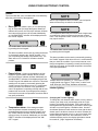
ALARM RESET
Power Failure
ALARM RESET
Temp
NOTE
Door Ajar
Temp
Door Ajar
ALARM RESET
This alarm condition can be reset by momentarily pressing
the "On/Off" keypad. If this alarm occurs it is recommended
that you check the condition of your stored contents, even
though the appliance is operating normally and the temper-
ature has recovered, as prolonged temperature excursions
could spoil perishables.
Interior lighting:
Changing the Tri-Color lighting:
To change the color between white, amber, or blue, with the
control out of sleep mode, momentarily press the "Light"
keypad. The keypad will illuminate. Then press and hold
the keypad and in approximately 3 seconds the interior light
will start to cycle through the 3 available colors. On solid
door/drawer product this will need to be done with the door/
drawer open to be able to observe the colors. Release the
keypad when the desired color is on, and your interior light
will be changed to that color. After selection of color for
solid door/drawer product, the display light feature should
be turned-off, ("Light" keypad not illuminated).
USING YOUR ELECTRONIC CONTROL
• Power failure - If power to the appliance is inter-
rupted the System Status indicator will turn-off and
the "Power Failure" indicator will ash. Additionally, an
"ALARM RESET" indicator will be displayed below the
"On/Off" keypad. No audible tone will sound. This alarm
condition can be reset by momentarily pressing the
"On/Off" keypad. If this alarm occurs, it is recommend-
ed that you check the condition of any perishables,
even if the appliance is operating normally and the tem-
perature has recovered, as prolonged power outages
could result in excessive temperature excursions which
may spoil perishables.
• Temperature alarm - If the storage compart-
ment temperature deviates excessively from your
set-point temperature for an extended period of time,
the "TEMP" indicator will ash, and an audible tone
will sound every 60 seconds. Additionally, an "ALARM
RESET" indicator will be displayed below the "ON/
OFF" keypad.
Multiple alarms are possible, i.e.- "Door Ajar" for a pro-
longed period may trigger a "Temp" alarm, in which case
both "Door Ajar" and "Temp" indicators will activate.
Alarms:
The control will alert you to conditions that could adversely
affect the performance of the appliance.
• Door ajar - If a drawer is open, or not closed prop-
erly, for more than 5-minutes the System Status OK
indicator will turn-off, the "Door Ajar" indicator will ash,
and a tone will sound every 60 seconds. Additionally,
an "ALARM RESET" indicator will be displayed below
the "On/Off" keypad.
This alarm condition can be reset by closing the drawer
or momentarily pressing the "On/Off" keypad, (i.e.-if
you are cleaning the storage compartment, etc.). The
alarm will recur in 5-minutes if the alarm condition
persists.
NOTE
The audible alarm can be muted, for each occurrence,
by pressing the lock keypad.
NOTE
The audible alarm can be muted, for each occurrence,
by pressing the lock keypad.
NOTE
NOTE
After a high temperature alarm condition, check all perish-
ables to ensure they are safe for consumption.
The temperature alarm may occur as a result of high usage
or introduction of warm contents to the storage compart-
ment. If the temperature alarm continues to occur, your unit
may require service.

13
OVERLAY DRAWER PANEL INSTALLATION
Full Overlay Panel Installation Instructions
Determine Wood Screw Requirements
1. A #10 pan head wood screw should be used to proper-
ly secure the overlay panel (See Figure 17). A quantity
of 16 screws are supplied with the unit in the literature
pack.
2. Use only pan head screws.
3. If your overlay panel is thinner than
5
⁄8" (15.9 mm)
you will need to purchase shorter screws. The longer
screws will break through the front of the panel.
Figure 14
Press and hold down this
tab on the wire connec-
tor and pull the connector
apart.
Figure 14a
• Never attempt to repair or perform maintenance on
the appliance until the main electrical power has been
disconnected. Turning the appliance control "OFF"
does not remove electrical power from the units wiring.
• Replace all parts and panels before operating.
!
WARNING
Electrocution Hazard
!
CAUTION
It is important to use the factory provided grille that came
with the product to assure proper air ow is maintained
through the condenser. The use of a custom grille is not
recommended and will void the warranty.
To enter Vacation Mode (with the control out of sleep
mode), press and hold the "On/Off" keypad until the display
goes past "OFF" and reads "VAC". The display will ash
"VAC" 3-times to acknowledge your request, then will
display "VAC" continuously until Vacation mode is exited.
A power outage will not exit Vacation mode, exiting can
only be accomplished manually. To exit Vacation mode and
return to normal operation, press and hold the "On/Off"
keypad until the control displays the temperature.
Vacation mode:
This operating mode can be used to save energy during
high cost energy periods, or when you won't be using your
appliance for an extended period of time by disabling the
lights, alarm tones, and keypad entry tones. Vacation mode
also serves as a Sabbath mode, disabling functions and
its controls in accordance with the weekly Sabbath and
religious holidays observed within the Orthodox Jewish
community. When used as Sabbath mode, you may open
or close a drawer at any time to access contents without
concern of directly turning on or off any lights, digital read-
outs, solenoids, fans, valves, compressor, icons, tones, or
alarms.
When activated, the display, alarm indicators and tones,
keypad touch tones, interior lights, and all options are dis-
abled. All keypad functions are disabled, with the exception
of the "On/Off" keypad which is required to exit Vacation-
mode. Storage compartment temperatures are monitored
and controlled at the settings prior to entering Vacation
mode.

14
Cut the overlay panel to the dimensions shown below in
Figure 18. On the top drawer only, drill the 2 counter-bored
holes which are clearance for screw heads on the face of
the top drawer and the lock hole at the bottom of the top
drawer only.
This is also a convenient time to locate and drill the holes
for your handle. Most often the handle is to match that of
the surrounding cabinetry. If your handle attaches from the
back-side of the custom panel, locate the mounting holes
while the panel is attached to the drawer and cabinet. After
the panel is removed from the drawer, drill the mounting
holes from the front, to the recommended diameter of the
handle manufacturer. Counter bore the back-side of the
panel so the screw heads do not interfere with the surface
of the drawer.
Step 2: Size the Overlay Panel
Figure 17
.35/.31
(9 mm/7.5 mm)
.50
(12.5)
Figure 15
Remove screws
Clips
Gasket
Figure 16
Step 1: Remove Drawers from unit.
1. Begin by pulling out the top drawer. (See Figure 14).
Remove screws securing drawer to slides (See Figure
15). Pull drawer forward, lift up and out to clear clips in
rear of drawer. Move drawer forward about 1" (2.5 cm)
and set down on slides. At the right rear corner of the
drawer disconnect the display wire harness (See Figure
14a). Remove the drawer from the unit by lifting up off
of the slides. Repeat for bottom drawer but disregard
the harness instructions as there is no wiring to the bot-
tom drawer.
2. Remove the drawer divider from the drawer and
remove the gasket from the drawer front. (See Figure
15). Do this by pulling the gasket out of the channel
that holds it to the drawer front. This will expose the
clearance holes for mounting the overlay panel. (See
Figure 19).
OVERLAY DRAWER PANEL INSTALLATION

15
Step 3: Attach the Overlay Panel to the Drawer
1. Set the overlay panel on drawer front face and align
edges. (See Figure 19). The custom overlay panel
should be ush with the top of the drawer and centered
on the width of the drawer. Clamp panel in position and
mark pilot hole locations. Pick the required pilot hole
size from "Table A" below and drill the pilot holes ensur-
ing not to drill all the way through the overlay panel.
Table A: Pilot Hole Drill Sizes for Wood Screws
Material Type #8 Wood Screw
Hardwood
1
⁄8 Diameter Pilot Hole
Softwood
7
⁄64 Diameter Pilot Hole
2. Insert wood screws through clearance holes and
tighten to secure overlay panel.
3. Reinstall gasket into channel. Make sure the corners
are fully inserted.
4. Place the drawer divider back into the drawer.
Figure 19
Overlay panel
ush with top
edge of drawer
Using clearance holes in
gasket channel mark
hole locations onto panel
Screw clearance
hole through
gasket extrusion
Panel
thickness
Figure 18
Figure 19a
14
29
⁄32"
(379 mm)
19"
(483 mm)
1
3
⁄16"
(30 mm)
1"(25 mm) diameter counter
bore
1
⁄4" (6 mm) deep
2 places, top drawer only.
Custom overlay
panel to be cen-
tered on width of
drawer.
11
7
⁄8"
(302 mm)
11
⁄32"
(8.8 mm)
1
⁄2" (12.7 mm)
diameter, top
drawer only
13
⁄16" (21 mm)
counterbore
7
⁄16" (12 mm)
deep, top
drawer only
This side
facing interior
2
3
⁄8"
(60 mm)
23
3
⁄4"
(603 mm)
OVERLAY DRAWER PANEL INSTALLATION

16
!
CAUTION
Step 5: Reinstall the Drawers
1. Fully extend drawer slides and place drawer on slides.
Be sure that drawer sits evenly on both slides and clips
slide into place in rear of drawer.
2. Re-install wire harness at rear corner of top drawer.
3. Re-install two screws through drawer into slides.
Cam stop
washer
Spring
washer
Cam
Set screw
Lock
Key
Retainer
nut
Screw
Brass
extension
(2 lengths
provided)
Figure 21
CAM
BRASS EXTENSION
SPRING
WASHER
NUT
LOCK
1/2 HOLE
13/16 COUNTER
BORE
WOOD PANEL
3/4 INCH
DOOR
INNER
PHILLIPS SCREW
Figure 20
Step 4: Install the Lock
Two (2) lock extensions are provided with the lock. Use the
longer extension for
3
⁄4" thick overlay panels and the shorter
one for
5
⁄8" thick overlay panels. Assemble the lock exten-
sion, cam stop washer, spring washer, and set screw to the
lock as shown in Figure 20 and 21.
Install this lock assembly into the lock hole in the overlay
panel and secure with the retaining nut on the back side
with a 15 mm socket and ratchet. Make sure the key slot in
the front of the lock is vertical.
Light assembly replacement
All models use an LED to illuminate the interior of the ap-
pliance. This component is very reliable, but should it fail,
contact a qualied service technician for replacement of the
LED.
In the Event of a Power Failure
If a power failure occurs, try to correct it as soon as pos-
sible. Minimize the number of drawer openings while the
power is off so as not to adversely affect the appliance's
temperature.
Care of Appliance
1. Avoid leaning on the drawer, you may bend the drawer
hinges or tip the appliance.
2. Exercise caution when sweeping, vacuuming or mop-
ping near the front of the appliance. Damage to the
grille can occur.
3. Periodically clean the interior of the appliance as
needed.
4. Periodically check and/or clean the front grille as
needed.
Front Grille
Be sure that nothing obstructs the required air ow open-
ings in front of the cabinet. At least once or twice a year,
brush or vacuum lint and dirt from the front grille area (see
page 4).
SHOCK HAZARD: Disconnect electrical power from the
appliance before cleaning with soap and water.
Cabinet
The painted cabinet can be washed with either a mild soap
and water and thoroughly rinsed with clear water. NEVER
use abrasive scouring cleaners.
Interior
Wash interior compartment with mild soap and water. Do
NOT use an abrasive cleaner, solvent, polish cleaner or
undiluted detergent.
CARE AND CLEANING

17
The following suggestions will minimize the
cost of operating your refrigeration appliance.
1. Do not install your appliance next to a hot appliance
(cooker, dishwasher, etc.), heating air duct, or other
heat sources.
2. Install product out of direct sunlight.
3. Ensure the front grille vents at front of appliance be-
neath drawer are not obstructed and kept clean to allow
ventilation for the refrigeration system to expel heat.
4. Plug your appliance into a dedicated power circuit. (Not
shared with other appliances).
5. When initially loading your new product, or whenever
large quantities of warm contents are placed within
refrigerated storage compartment, minimize drawer
openings for the next 12 hours to allow contents to pull
down to compartment set temperature.
6. Maintaining a relatively full storage compartment will
require less appliance run time than an empty compart-
ment.
7. Ensure drawer closing is not obstructed by contents
stored in your appliance.
8. Allow hot items to reach room temperature before plac-
ing in product.
9. Minimize drawer openings and duration of drawer
openings.
10. Use the warmest temperature control set temperature
that meets your personal preference and provides the
proper storage for your stored contents.
11. When on vacation or away from home for extended
periods, set the appliance to warmest acceptable
temperature for the stored contents.
12. Set the control to the “off” position if cleaning the
appliance requires the drawer to be open for an ex-
tended period of time.
If Service is Required:
• If the product is within the rst year warranty period
please contact your dealer or call Marvel Customer
Service at 800.223.3900 for directions on how to obtain
warranty coverage in your area.
• If the product is outside the rst year warranty period,
Marvel Customer Service can provide recommenda-
tions of service centers in your area. A listing of autho-
rized service centers is also available at www.marvelre-
frigeration.com under the service and support section.
• In all correspondence regarding service, be sure to
give the service number, serial number, and proof of
purchase.
• Try to have information or description of nature of the
problem, how long the appliance has been running, the
room temperature, and any additional information that
may be helpful in quickly solving the problem.
• Table "B" is provided for recording pertinent information
regarding your product for future reference.
For Your Records
Date of Purchase
Dealer’s name
Dealer’s Address
Dealer’s City
Dealer’s State
Dealer’s Zip Code
Appliance Serial Number
Rev. Letter
Appliance Service Number
Date Warranty Card Sent (Must
be within 10 days of purchase).
Table B
ENERGY SAVING TIPS AND OBTAINING SERVICE

18
!
CAUTION
In the unlikely event you lose cooling in your unit, do not
unplug the product from the electric supply, but do call
a qualied service technician immediately. It is possible
that the loss of cooling capacity is a result of excessive
frost build-up on the evaporator cooling coil. In this case,
removing power to the unit will result in the melting of this
excessive quantity of ice, which could generate melt water
that exceeds the capacity of the defrost drain system and
could result in water damage to your home. The end-user
will be ultimately responsible for any water damage caused
by prematurely turning the unit off without appropriately
managing the excess water run-off.
• Never attempt to repair or perform maintenance on
the appliance until the main electrical power has been
disconnected. Turning the appliance control "OFF"
does not remove electrical power from the units wiring.
• Replace all parts and panels before operating.
!
WARNING
Electrocution Hazard
Before You Call for Service
If the appliance appears to be malfunctioning, read through
this manual rst. If the problem persists, check the trouble-
shooting guide below. Locate the problem in the guide and
refer to the cause and its remedy before calling for service.
The problem may be something very simple that can be
solved without a service call. However, it may be required
to contact your dealer or a qualied service technician.
TROUBLESHOOTING
Problem Possible Cause Remedy
Appliance not cold enough
(See “Adjusting the temperature" on
page 11)
• Control set too warm
• Content temperature not stabi-
lized.
• Excessive usage or prolonged
drawer openings.
• Airow to front grille blocked.
• Drawer gasket not sealing prop-
erly.
• Adjust temperature colder. Al-
low 24 hours for temperature to
stabilize.
• Allow temperature to stabilize for
at least 24 hours.
• Airow must not be obstructed to
front grille. See “clearances” on
page 4.
• Adjust or replace drawer gasket.
Appliance too cold
(See “Adjusting the Temperature” on
page 11)
• Control set too cold
• Drawer gasket not sealing prop-
erly.
• Adjust temperature warmer.
Allow 24 hours for temperature to
stabilize.
• Adjust or replace drawer gasket.
No interior light. • Failed LED light assembly or light
switch.
• Contact a qualied service techni-
cian.
Light will not go out when drawer is
closed
• Drawer not activating light switch.
• Failed light switch
• Appliance not level, level appli-
ance, (See page 4, “leveling legs”)
• Contact a qualied service techni-
cian.
Noise or Vibration • Appliance not level
• Fan hitting tube obstruction.
• Level appliance, see “Leveling
Legs” on page 4.
• Contact a qualied service techni-
cian.
Appliance will not run. • Appliance turned off
• Power cord not plugged in.
• No power at outlet.
• Turn appliance on. See “Starting
your appliance” on page 10.
• Plug in power cord.
• Check house circuit.

19
HOUSEHOLD PRODUCT WARRANTY
Marvel Refrigeration (Marvel) Limited Warranty
ONE YEAR LIMITED PARTS & LABOR WARRANTY
For one year from the date of original purchase, this warranty covers all parts and labor to repair or replace any part of the product that proves to
be defecve in materials or workmanship. For products installed and used for normal residenal use, material cosmec defects are included in this
warranty, with coverage limited to 60 days from the date of original purchase. All service provided by Marvel under the above warranty must be
performed by a Marvel factory authorized servicer, unless otherwise specied by Marvel. Service provided during normal business hours.
TWO YEAR LIMITED PARTS & LABOR WARRANTY (MARVEL PROFESSIONAL PRODUCTS)
For two years from the date of original purchase, this warranty covers all parts and labor to repair or replace any part of the product that proves to
be defecve in materials or workmanship. For products installed and used for normal residenal use, material cosmec defects are included in this
warranty, with coverage limited to 60 days from the date of original purchase. All service provided by Marvel under the above warranty must be
performed by a Marvel factory authorized servicer, unless otherwise specied by Marvel. Service provided during normal business hours.
AVAILABLE THIRD YEAR LIMITED WARRANTY (MARVEL PROFESSIONAL PRODUCTS)
For designated Marvel Professional product, Marvel oers a one year extension of the two year warranty coverage from the date of purchase, free
of charge. To take advantage of this third year warranty, you must register your product with Marvel within 60 days from the date of purchase at
marvelrefrigeraon.com and provide proof of purchase.
LIMITED FIVE YEAR SEALED SYSTEM WARRANTY
For ve years from the date of original purchase, Marvel will repair or replace the following parts, labor not included, that prove to be defecve in
materials or workmanship: compressor, condenser, evaporator, drier, and all connecng tubing. All service provided by Marvel under the above war-
ranty must be performed by a Marvel factory authorized servicer, unless otherwise specied by Marvel. Service provided during normal business
hours.
WARRANTY TERMS
These warranes apply only to products installed in any one of the y states of the United States, the District of Columbia, or the ten provinces of
Canada. The warranes do not cover any parts or labor to correct any defect caused by negligence, accident or improper use, maintenance, instal-
laon, service, repair, acts of God, re, ood or other natural disasters. The product must be installed, operated, and maintained in accordance with
the Marvel User Guide.
The remedies described above for each warranty are the only ones that Marvel will provide, either under these warranes or under any warranty
arising by operaon of law. Marvel will not be responsible for any consequenal or incidental damages arising from the breach of these warranes
or any other warranty, whether express, implied, or statutory. Some states do not allow the exclusion or limitaon of incidental or consequenal
damages, so the above limitaon or exclusion may not apply to you. These warranes give you specic legal rights, and you may also have other
rights which vary from state to state.
Any warranty that may be implied in connecon with your purchase or use of the product, including any warranty of merchantability or any war-
ranty t for a parcular purpose is limited to the duraon of these warranes, and only extends to ve years in duraon for the parts described
in the secon related to the ve year limited warranty above. Some states do not allow limitaons on how long an implied warranty lasts, so the
above limitaons may not apply to you.
• The warranes only apply to the original purchaser and are non-transferable.
• These warranes cover products installed and used for normal residenal use only.
• The warranes apply to units operated outside only if designed for outdoor use by model and serial number.
• Replacement water lters, light bulbs, and other consumable parts are not covered by these warranes.
• The start of Marvel’s obligaon is limited to four years aer the shipment date from Marvel.
• In-home instrucon on how to use your product is not covered by these warranes.
• Food, beverage, and medicine loss are not covered by these warranes.
• If the product is located in an area where Marvel factory authorized service is not available, you may be responsible for a trip charge or
you may be required to bring the product to a Marvel factory authorized service locaon at your own cost and expense.
• Units purchased aer use as oor displays, and/or cered recondioned units, are covered by the limited one year warranty only and no
coverage is provided for cosmec defects.
• Signal issues related to Wi-Fi connecvity are not covered by these warranes.
For parts and service assistance, or to nd Marvel factory authorized service near you, contact Marvel Refrigeraon:
MarvelRefrigeraon.com • techsupport@MarvelRefrigeraon.com • +616.754.5601
1260 E. Van Deinse St., Greenville, MI 48838

Marvel Refrigeration
All specications and product designs subject to change without notice. Such revisions do not entitle
the buyer to corresponding changes, improvements, additions, replacements or compensation for
previously purchased products.
www.marvelrefrigeration.com
1260 E. VanDeinse St.
Greenville MI 48838
800.223.3900
41014810-EN Rev E
1/14/20
La page est en cours de chargement...
La page est en cours de chargement...
La page est en cours de chargement...
La page est en cours de chargement...
La page est en cours de chargement...
La page est en cours de chargement...
La page est en cours de chargement...
La page est en cours de chargement...
La page est en cours de chargement...
La page est en cours de chargement...
La page est en cours de chargement...
La page est en cours de chargement...
La page est en cours de chargement...
La page est en cours de chargement...
La page est en cours de chargement...
La page est en cours de chargement...
La page est en cours de chargement...
La page est en cours de chargement...
La page est en cours de chargement...
La page est en cours de chargement...
-
 1
1
-
 2
2
-
 3
3
-
 4
4
-
 5
5
-
 6
6
-
 7
7
-
 8
8
-
 9
9
-
 10
10
-
 11
11
-
 12
12
-
 13
13
-
 14
14
-
 15
15
-
 16
16
-
 17
17
-
 18
18
-
 19
19
-
 20
20
-
 21
21
-
 22
22
-
 23
23
-
 24
24
-
 25
25
-
 26
26
-
 27
27
-
 28
28
-
 29
29
-
 30
30
-
 31
31
-
 32
32
-
 33
33
-
 34
34
-
 35
35
-
 36
36
-
 37
37
-
 38
38
-
 39
39
-
 40
40


dans d''autres langues
- English: Marvel ML24BNS1RS User guide
Documents connexes
-
Marvel ML24RDP3NP Mode d'emploi
-
-
-
Marvel MO24RD Mode d'emploi
-
-
Marvel MP15CLP2LP Mode d'emploi
-
Marvel MP15WS1F4RP Mode d'emploi
-
Marvel ML24FAS1LS Mode d'emploi
-
-
Marvel ML24FAS1RS Mode d'emploi
