Bertazzoni MAST366RTBXT Manuel utilisateur
- Catégorie
- Plaques électriques
- Taper
- Manuel utilisateur

BERTAZZONI
INSTALLATION & USER MANUAL
GAS RANGETOP
3100515
WWW.BERTAZZONI.COM

2
/ Table of contents
TABLE OF CONTENTS
INSTALLATION
WARNINGS ___________________________________________________________________
DATA RATING LABEL ___________________________________________________________
BEFORE INSTALLATION ________________________________________________________
VENTILATION PREPARATION ____________________________________________________
SPECIFICATIONS ______________________________________________________________
CLEARENCE DIMENSIONS ______________________________________________________
INSTALLATION REQUIREMENTS _________________________________________________
Electrical ___________________________________________________________________
Gas ________________________________________________________________________
ELECTRICAL CONNECTION _____________________________________________________
WIRING DIAGRAM _____________________________________________________________
GAS CONNECTION _____________________________________________________________
Manual shut-off valve _________________________________________________________
Flexible connections __________________________________________________________
Pressure test-point stopper valve _______________________________________________
Pressure regulator ____________________________________________________________
INSTALLATION ________________________________________________________________
Unpackaging the rangetop_____________________________________________________
Installing the worktop frontguard ________________________________________________
Installing the island trim _______________________________________________________
Installing backguard (optional) __________________________________________________
GAS CONVERSION _____________________________________________________________
INSTALLATION CHECKLIST ______________________________________________________
FINAL PREPARATION ___________________________________________________________
BERTAZZONI SERVICE _________________________________________________________
USE ________________________________________________________________________
WARNINGS ____________________________________________________________________
WORKTOP AND KNOBS LAYOUT _________________________________________________
GAS COOKTOP ________________________________________________________________
ELECTRIC GRIDDLE ____________________________________________________________
KEEPING YOUR BERTAZZONI CLEAN _____________________________________________
TROUBLESHOOTING ___________________________________________________________
TWO YEARS LIMITED WARRANTY ________________________________________________
4
4
6
6
7
7
9
10
10
10
10
11
12
12
12
12
13
14
14
14
15
15
16
18
18
18
19
20
22
23
25
26
27
28

3
/ Models
Models
MAST366RTBXT
PROF366RTBXT
MAST366RTXE
MAST486GRTBXT
PROF486GRBXT
Models

4
/ Warnings
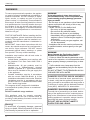
WARNINGS
To ensure proper and safe operation, the applian-
ce must be properly installed and grounded by a
qualifi ed technician. DO NOT attempt to adjust,
repair, service, or replace any part of your ap-
pliance unless it is specifi cally recommended in
this manual. All other servicing should be referred
to a qualifi ed servicer. Have the installer show you
the location of the gas shutoff valve and how to
shut it off in an emergency. A certifi ed technician
is required for any adjustments or conversions to
Natural or LP gas.
FOR THE INSTALLER: Before installing the Ber-
tazzoni appliance, please read these instructions
carefully. This appliance shall be installed in ac-
cordance with the manufacturer’s installation in-
structions.
IMPORTANT: Leave these instructions with the
owner, who should save them for local inspector’s
use and for future reference. DO NOT remove
permanently affi xed labels, warnings, or plates
from product. This may void the warranty.
Installation must conform with all local codes. In
the absence of codes:
• United States: installation must conform with
the National Fuel Gas Code ANSI Z223.1
INFPA54
• Massachusetts: All gas products must be
installed by a “Massachusetts” licensed
plumber or gasfi tter. A “T” type handle manual
valve must be installed in the gas supply line
to the appliance.
• Canada: Installation must be in accordance
with the current CAN/CGA B149.1 & 2 Gas
Installation codes and/or local codes. Electrical
installation must be in accordance with the
current CSA C22.1 Canadian Electrical Codes
Part 1 and/or local codes.
This rangetop is NOT designed for installation
in manufactured (mobile) homes or recreational
park trailers.
DO NOT install this range outdoors.
This appliance must be properly grounded.
Grounding reduces the risk of electric shock by
providing a safe pathway for electric current in the
event of a short circuit.
Warning!
To avoid risk of property damage, personal
injury or death; follow information in this ma-
nual exactly to prevent a fi re or explosion.
WARNING!
If the information in these instructions is
not followed exactly, a fi re or explosion may
result causing property damage, personal
injury or death.
- Do not store or use gasoline or other fl ammable
vapors and liquid in the vicinity of this or any
other appliance.
- WHAT TO DO IF YOU SMELL GAS
•Do not try to light any appliance.
•Do not touch any electrical switch.
•Do not use any phone in your building.
•Immediately call your gas supplier from a
neghbor’s phone. Follow the gas supplier’s
instructions.
•If you cannot reach your gas suppliers, call
the fi re department.
- Installation and service must be performed by
a qualifi ed installer, service agency or the gas
supplier
WARNING!
Never Operate the Top Surface Cooking
Section of this Appliance Unattended.
- Failure to follow this warning statement could
result in fi re, explosion, or burn hazard that could
cause property damage. personal injury, or dea-
th.
- If a fi re should occur, keep away from the
appliance and immediately call your fi re depart-
ment.
DO NOT ATTEMPT TO EXTRINGUISH AN OIL/
GREASE FIRE WITH WATER
DANGER!!! ELECTRIC SHOCK HAZARD!!!
To avoid risk of electrical shock, personal injury
or death, verify that the appliance has been pro-
perly grounded in accordance with local codes or
in absence of codes, with the National Electrical
Code (NEC). ANSI/NFPA 70- latest edition.
DANGER!!! GAS LEAK HAZARD!!!
To avoid risk of personal injury or death, leak-te-
sting of the appliance must be conducted accor-
ding to the manufacturer’s instructions. Before
placing appliance in operation, always check for
gas leaks with water and soap solution.
DO NOT USE AN OPEN FLAME TO
CHECK FOR GAS LEAKS.

5
/ Warnings
WARNING:
Cancer and Reproductiv Harm-
www.P65Warnings.ca.gov
.

6
/ Data rating label / Before installation
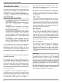
The data rating label shows the model and serial
number of the rangetop. It is located under the
rangetop and in the last page of this manual.
• DO NOT remove permanently affi xed labels,
warnings, or plates from product. This may
void the warranty.
• This appliance shall only be installed by an
authorized professi
onal.
• This appliance shall be installed in accordance
with the manufacturer’s installation
instructions.
• This appliance must be installed in accordance
with the norms & standards of the country
where it will be installed.
• The installation of this appliance must conform
to local codes and ordinances. In the absence
of local codes, Installations must conforms to
American National Standards, National Fuel
Gas Code ANSI Z223.1 – latest edition/NFPA
54 or B149.1.
• The appliance, when installed, must be
electrically grounded in accordance with local
codes or, in the absence of local codes, with
the National Electrical Code, ANSI/NFPA 70.
If local codes permit, a fl exible metal appliance
connection conduit with the new AGA or CGA cer-
tifi ed design, max. 5 feet (1,5 m) long, ½” I.D. is
recommended for connecting this appliance to the
gas supply line. Do not bend or damage the fl exi-
ble connector when moving the appliance.
This appliance must be used with the pressure
regulator provided.
The regulator shall be properly installed in order to
be accessible when the appliance is installed in its
fi nal location. The pressure regulator must be set
for the type of gas to be used. The pressure regu-
lator has ½” female pipe thread. The appropriate
fi tting must be determined based on the size of
your gas supply line, the fl exible metal connector
and the shutoff valve.
The appliance must be isolated from the gas sup-
ply piping system by closing its individual manual
shutoff valve during any pressure testing of the
gas supply piping system at test pressures equal
to or less than 1/2 PSI (13,8” w.c. or 3,5 kPa).
All opening and holes in the wall and fl oor, back
and under the appliance shall be sealed before
installation of the appliance.
A manual valve shall be installed in an accessible
location in the gas line external to the appliance
for the purpose of turning on or shutting off gas to
the appliance.
Type of gas
This range can be used with Natural or LP/Pro-
pane gas. The range is shipped from the factory
for use with the gas indicated on the rating label
positioned on the lower face of the control panel
and in the last page of this manual. A step by step
conversion procedure is also included in this ma-
nual and in each conversion kit.
Gas pressure
The maximum inlet gas supply pressure inco-
ming to the gas appliance pressure regulator is
1/2 PSI (13,8’’ iwc or 3,5 kPa). The minimum gas
supply pressure for checking the regulator setting
shall be at least 1“ iwc (249 Pa) above the inlet
specifi ed manifold pressure to the appliance; this
operating pressure is 4” iwc (1.00 kPa) for Natural
Gas and 10” iwc (2.50 kPa) for LP Gas.
Room ventilation
An exhaust fan may be used with the appliance;
in each case it shall be installed in conformity
with the appropriate national and local standards.
Exhaust hood operation may aff ect other vented
appliances; in each case it shall be installed in
conformity with the appropriate national and local
standards.
Warning
This appliance should not be installed with a
ventilation system that directs air in a downward
direction toward the range. This type of ventila-
tion system may cause ignition and combustion
problems with the appliance resulting in personal
injury, property damage, or unintended operation.
Ventilating systems that direct the air upwards do
not have any restriction.
Do not use aerosol sprays in the vicinity of
this appliance while it is in operation.
DATA RATING LABEL
BEFORE INSTALLATION

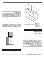
7
This rangetop will best perform when installed
with Bertazzoni exhaust hoods. These hoods
have been designed to work in conjunction with
the Bertazzoni range and have the same fi nish for
a perfect look.
Before installation of the exhaust hood, consult lo-
cal or regional building and installation codes for
additional specifi c clearance requirements.
Refer to the rangetop hood installation instructions
provided by the manufacturer for additional infor-
mation.
Select Hood and Blower Models:
• For wall installations, the hood should be
equal or larger width than the range. Where
space permits, a hood larger than the range
may be desirable for improved ventilation
performance.
• For island installations, the hood width should
overhang the range by a minimum of 3” (76
mm) on each side.
Hood Placement:
• For best removal of smoke and odors, the
lower edge of the hood should be installed
between 25 1/2” (65 cm) and 31 1/2” (80 cm)
above the range cooking surface.
• If the hood contains any combustible materials
(i.e. a wood covering), it must be installed at a
minimum of 36” (914 mm) above the cooking
surface.
Consider Make-Up Air:
Due to the high volume of ventilation air, a sour-
ce of outside replacement air is recommended.
This is particularly important for tightly sealed
and insulated homes. A qualifi ed heating and
ventilating contractor should be consulted.
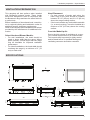
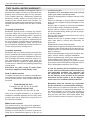
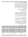
/ Ventilation preparation / Specifi cations
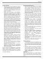
VENTILATION PREPARATION
SPECIFICATIONS
A
36’’ 48’’
A
27''
/8
25''
/16
36''
48''
7''
/85
7''
/85
22''
/16
23''
/4
9
5''
/161
1''
/169
25''
/16
2''
/21
13''
/16
1''
/85
20''
/8
5
2''
/21
1''
/16
11
1''
/85
24''
/16
9

8
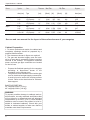
/ Specifi cations - Cabinet
Burner
Auxiliary
Semi-rapid
Rapid
Dual burner
Injector
diam.[mm]
0.90
0.54
1.18
0.70
1.55
0.92
0.80+2.10
0.50+1.20
Gas
Type
NG
LP (Propane)
NG
LP (Propane)
NG
LP (Propane)
NG
LP (Propane)
Pressure
[iwc]
4’’
10’’
4’’
10’’
4’’
10’’
4’’
10’’
Max Rate
[Btu/hr]
3,500
3,300
5,900
5,500
10,400
9,500
19,000
19,000
Min Rate
[Btu/hr]
900
900
1,500
1,500
2,500
2,500
1,300
1,300
[W]
1,025
967
1,729
1,611
3,047
2,783
5,567
5,567
[W]
264
264
439
439
732
732
381
381
By-pass
diam.[mm]
Regulated
0.29
Regulated
0.36
Regulated
0.47
Regulated
0.34/0.65
See use and care manual for the layout of the surface burners of your rangetop
B
urner In
j
ector
G
a
s
Pre
ss
ure Max Rate Min Rate
By
-pas
s
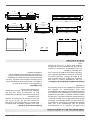
Cabinet Preparation
1. To ensure professional results, the cabinet and
countertop openings should be prepared by a
qualifi ed cabinet worker.
2. The clearances shown in fi gure are required.
3. The gas and electrical supply must be locat-
ed in an area that is accessible without requiring
removal of the cooktop. The appliance electrical
power cord and gas pipe connection are located
on the left rear.
• Prepare the fi nished opening for the rangetop
according to dimensions shown in the
illustration on the follows page.
• The platform must include a cut-out at the right
rear for electrical and gas supply connections.
It must be level to ensure the cooking surface
is level. Refer to the chart below for minimum
base support.
BASE SUPPORT MIN
36” rangetop 250 lb (113 kg)
48” rangetop 300 lb (136 kg)
WARNING
To prevent possible damage to cabinets and ca-
binet fi nishes, use only materials and fi nishes that
will not discolor or delaminate and will withstand
temperatures up to 230°F (110°C). Heat resistant
adhesive must be used if the product is to be in-
stalled in laminated cabinetry. Check with your
builder or cabinet supplier to make sure that the
materials meet these requirements.

9
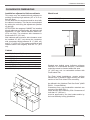
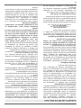
/ Clearence dimensions
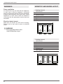
CLEARENCES DIMENSIONS
Installation adjacent to kitchen cabinets
This range may be installed directly adjacent to
existing countertop high cabinets (36” or 91.5 cm
from the fl oor).
For the best look, the worktop should be level with
the cabinet countertop. This can be accomplished
by raising the unit using the adjustment spindles
on the legs.
ATTENTION: the rangetop CANNOT be installed
directly adjacent to kitchen walls, tall cabinets, tall
appliances, or other vertical surfaces above 36”
(91.4 cm) high. The minimum side clearance in
such cases is 6” (15.2 cm).
Wall cabinets with minimum side clearance must
be installed 18” (45.7 cm) above the countertop
with countertop height between 35 ½” (90.2 cm)
and 37 ¼” (94.6 cm). The maximum depth of wall
cabinets above the rangetop shall be 13” (33.0
cm).
Cabinet
Shaded area behind range indicates minimum
clearance to combustible surfaces, combustible
materials cannot be located within this area.
12” (305 mm) min. to combustible surface with
Flush Island Trim
For Flush Island installations, counter surface
should have a cantilever edge meeting the back
section of the Flush Island Trim accessory.
As defi ned in the “National Fuel Gas Code” (ANSI
Z223.1, Current Edition).
Clearances from non-combustible materials are
not part of the ANSI Z21.1
scope and are not certifi ed by CSA. Clearances of
less than 12” (305 mm)
must be approved by the local codes and/or by
the local authority having jurisdiction.
Metal hood
A
B
C
D
E
F
G
L
B
H
36’ (91,5 cm) or 48” (122 cm)
36’’ (91,5 cm) hood with combustible materials
13’’ (33,0 cm)
18’’ (45,7 cm)
6’’ 5/8(16,8 cm)
6’ (15,2 cm)
min 3” 7/16 max 5” 3/16 (min 8,7cm max 13 cm)
25’’ 3/16(64 cm)
min 25” 1/2 (65 cm)
min 12” (30,50 cm)
B
H
A
F
D
B
C
E
G
F
L

10
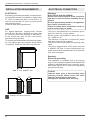
/ Installation requirements / Electrical connection
ELECTRICAL
A properly-grounded horizontally- mounted electri-
cal receptacle should be installed no higher than
27” (68.6 cm) above the fl oor, no less than 2” (5
cm) and no more than 15” (38,1 cm) from the left
side (facing product).
Check all local code requirements.
GAS
An agency-approved, properly-sized manual
shut-off valve should be installed no higher than
27” (68.6 cm) above the fl oor and no less than 2”
(5 cm) and no more than 15” (38.1 cm) from the
right side (facing product).
To connect gas between shut-off valve and regula-
tor, use agency-approved, properly sized fl exible
or rigid pipe. Check all local code requirements.
Warning!
ELECTRICAL SHOCK HAZARD
Disconnect electrical power at the circuit bre-
aker box or fuse box before installing the ap-
pliance.
Provide appropriate ground for the appliance.
Use copper conductors only.
Failure to follow these instructions could re-
sult in serious injury or death.
This unit is manufactured for a polarized, groun-
ded 120 volt/60 Hz, 16 amp system.
Electric power consumption is about 200 W for
36”, 1200W for 48”
The minimum of 102 VAC is required for proper
operation of gas ignition systems.
The circuit must be grounded and properly pola-
rized.
The unit is equipped with a SJT power cord and
a NEMA 5-15P plug. In case of replacement, the
power cord shall be replaced with one of the same
type, size and length.
Warning!
Electrical grounding
This appliance is equipped with a three-prong
plug for your protection against shock hazard and
should be plugged directly into a properly groun-
ded socket. Do not cut or remove the grounding
prong from this plug.
Caution
Label all wires prior to disconnecting when
servicing controls. Wiring errors can cause
improper and dangerous operation.
Verify proper operation after servicing.
INSTALLATION REQUIREMENTS ELECTRICAL CONNECTION
installation area for the connection
E
G
15'' 15''
27''
PLQPD[

11
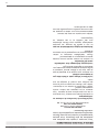
/ Wiring diagram
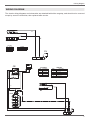
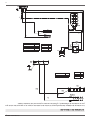
WIRING DIAGRAM
The electric wiring diagrams and schematics are attached behind the rangetop, and should not be removed
except by a service technician, then replaced after service.
*
/
1
*9
0
6LPE 'HVFULSWLRQ
JU *UHHQHDUWK
Q %ODFNOLQH
EL :KLWHQHXWUDO
&2/2856
6LPE 'HVFULSWLRQ
,*1 ,JQLWLRQ0LFURVZLWFKHV
* 6SDUN*HQHUDWRU
/(*(1'$
EL
EL
,*1
Q
Q
*
/
1
*9
0
6LPE 'HVFULSWLRQ
U5HG
JU *UHHQHDUWK
Q %ODFNOLQH
EL :KLWHQHXWUDO
&2/2856
6LPE 'HVFULSWLRQ
,*1 ,JQLWLRQ0LFURVZLWFKHV
* 6SDUN*HQHUDWRU
*( *ULGGOH7KHUPRVWDW
5*5 *ULGGOHHOHPHQW
766 6DIHW\7KHUPRVWDW
/(*(1'$
EL
Q
EL
JY
EL
,*1
Q
Q
5*5
766
6
*(
EL
Q
EL
EL
U
U
D
U
Q

12
/ Gas connection
Warning!
DO NOT USE AN OPEN FLAME WHEN
CHECKING FOR LEAKS!
Leak testing of the appliance shall be conducted
according to the manufacturer’s instructions. Be-
fore placing the oven into operation, always check
for leaks with soapy water solution or other accep-
table method.
Check for gas leakage with soapy water solution or
other acceptable methods in all gas connections
installed between inlet gas pipe of the appliance,
gas regulator, till to the manual shut-off valve.
All gas connections must comply with national and
local codes. The gas supply line (service) must
be the same size or greater than the inlet line of
the appliance. This rangetop uses a 1/2” NPT inlet
(see drawing below for details of gas connection).
On all pipe joints use appropriate sealant resistant
to gas to joint the adapter to rangetop manifold
use only the blue gasket supplied.
If necessary, the appliance must be converted by
the dealer, by a factory-trained professional or by
a qualifi ed licensed plumber or gas service com-
pany.
Gas conversion is important for safe and eff ecti-
ve use of the appliance. It is the responsibility of
the dealer and the owner of the range to perform
the appropriate gas conversion following the di-
rections of the manufacturer.
THE GAS CONVERSION PROCEDURE IS
DESCRIBED IN THIS MANUAL AND IN THE
PACKAGE CONTAINING THE CONVERSION
NOZZLES SHIPPED WITH EVERY RANGETOP.
Please provide the service person with this ma-
nual before work is started on the rangetop.
MANUAL SHUT-OFF VALVE
THIS VALVE IS NOT SHIPPED WITH THE AP-
PLIANC AND MUST BE SUPPLIED BY THE IN-
STALLER.
The manual shut-off valve must be installed in the
gas service line between the gas hook-up on the
wall and the appliance inlet, in a position where it
can be reached quickly in the event of an emer-
gency.
In Massachusetts: A ‘T’ handle type manual
gas valve must be installed in the gas supply line
to this appliance.
FLEXIBLE CONNECTIONS
In case of installation with fl exible couplings and/
or quick-disconnect fi ttings, the installer must use
a heavy-duty, AGA design-certifi ed commercial
fl exible connector of at least 1/2” (1.3 cm) ID NPT
(with suitable strain reliefs) in compliance with
ANSI Z21.41 and Z21.69 standards.
In Massachusetts: The unit must be installed
with a 36” (3-foot) long fl exible gas connector.
In Canada: use CAN 1-6.10-88 metal connec-
tors for gas appliances and CAN 1-6.9 M79 quick
disconnect device for use with gas fuel.
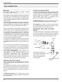
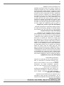
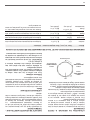
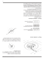
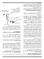
PRESSURE TEST-POINT STOPPER
VALVE
To avoid gas leaks, the pressure test-point stop-
per valve and gasket supplied with the rangetop
must be installed on the gas fi tting at the back of
the rangetop according to the diagram below.
GAS CONNECTION
GAS PIPE
GASKET
PRESSURE TEST-POINT
STOPPER
GAS CONNECTION ADAPTOR
1/2’’NPT WITH PRESSURE TEST
POINT 1/8’’ NPT (TO BE FIXED
TOWARD EXTERNAL SIDE OF
THE APPLIANCE)
ELBOW

13
/ Gas connection
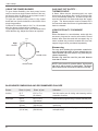
PRESSURE REGULATOR
Since service pressure may fl uctuate with local
demand, every gas cooking appliance must be
equipped with a pressure regulator on the inco-
ming service line for safe and effi cient operation.
The pressure regulator shipped with the applian-
ce has two female threads ½” NPT. The regulator
shall be installed properly in order to be accessible
when the appliance is installed in its fi nal position.
Manifold pressure should be checked with a ma-
nometer and comply with the values indicated be-
low:
Natural gas 4.0” iwc
LP/Propane 10.0” iwc
Incoming line pressure upstream from the regula-
tor must be 1” iwc higher than the manifold pres-
sure in order to check the regulator.
The regulator used on this range can withstand a
maximum input pressure of 1/2 PSI (13,8” iwc or
3,5 kPa) If the line pressure exceeds that amount,
a stepdown regulator is required.
The appliance, its individual shut-off valve, and
the pressure regulator must be disconnected from
the gas line during any pressure testing of that sy-
stem at pressures in excess of 1/2 PSI (13,8” iwc
or 3,5 kPa).
The individuaL manual shut-off valve must be in
the OFF position during any pressure testing of
the gas supply piping system at test pressures
equal to or less than 1/2 PSI (13,8” iwc or 3,5 kPa).
Warning
Before carrying out any servicing operation di-
sconnect the appliance from gas and electric
supply and extra appliance from fi nal installation
place in order to have access to the appliance for
proper servicing intervention.

14
/ Installation
APPLIANCE INSTALLATION
Unpacking the rangetop
• Remove all packing materials from the
shipping pallet but leave the adhesive-backed
foam layer over brushed-metal surfaces to
protect it from scratches until the range is
installed in its fi nalposition. Only the fi lm on
the side panels should be removed before
inserting the rangetop between the cabinets.
• Examine the appliance after unpacking it. In
the event of transport damage, do not plug
it. Take pictures of the damage and report it
immediately to the freight forwarder.
• The grates, griddle plate, burner caps, and
oven racks should be removed to facilitate
handling.
•
INSTALLING THE WORKTOP
FRONTGUARD
To increase the clearance between the front edge
of the worktop and the burners, it is possible to
install a front guard for the worktop.
To install the front guard,
• Locate the two fi xing holes on the end of the
front guard.
• Locate the two fi xing holes on the bottom facet
of the worktop
• Fix the front guard with it’s two screws
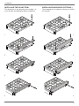
INSTALLATION

15
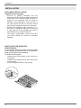
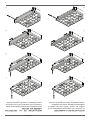
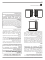
INSTALLING THE ISLAND TRIM
The island trim is only placed on the cooktop, re-
move all tape and packaging before installing it.
INSTALLING BACKGUARD (OPTIONAL)
The backguard is an optional contact you dealer
for buying it.
/ Installation
1 1
2 2
3
3
4 4

16
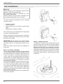
GAS CONVERSION
Warning!
Before carrying out this operation, disconnect the
appliance from gas and electricity.
Gas conversion shall be conducted by a fac-
tory-trained professional.
Call the customer service hotline to identify a fac-
tory-trained professional near your home.
The gas conversion procedure for this rangetop
includes 4 steps:
• Pressure regulator
• Surface burners
• Visual checks prior to closure of oven bottom
panel
• Adjustment of minimum setting
The conversion is not completed if all 4 steps have
not been concluded properly.
Before performing the gas conversion, locate the
package containing the replacement nozzle ship-
ped with every range.
IMPORTANT: Each nozzle has a number indica-
ting its fl ow diameter printed on the body. Consult
the table number 1 for matching nozzles to bur-
ners.
Save the nozzles removed from the rangetop for
future use.
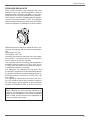
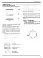
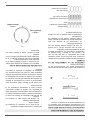
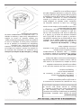
Step 1: pressure regulator
The pressure regulator supplied with the applian-
ce is a convertible type pressure regulator for use
with Natural Gas at a nominal outlet pressure of
4” iwc or LP gas at a nominal outlet pressure of
10”iwc. and it is pre-arranged from the factory to
operate with one of these gas/pressure as indica-
ted in the labels affi xed on the appliance, package
and Instruction booklet.
To convert the regulator for use with the other gas:
Unscrew by hand the upper cap of the regula-
tor, remove the white plastic attachment from the
cap, reverse its direction and screw it again fi rm-
ly against the cap. The white plastic attachment
has arrows indicating the position for natural gas
(NAT) and LP gas (LP).
Screw by hand the metal cap in the original posi-
tion on the regulator.
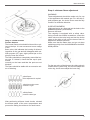
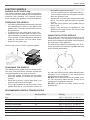
Step 2: surface burners
To replace the nozzles of the surface burners, lift
up the burners and unscrew the nozzles shipped
with the rangetop using a 7 mm (sochet wrench).
Replace nozzles using the conversion set sup-
plied with the rangetop or by a Bertazzoni authori-
zed parts warehouse. Each nozzle has a number
indicating its fl ow diameter printed on the body.
Consult the table number 1 and matching nozzles
to burners.
/ Gas conversion
LP
NAT

17
Step 3: visula checks
Surface burners
The burner fl ame color should be blue with no yel-
low on the tips. It is not uncommon to see orange
in the
fl ame color; this indicates the burning of airborne
impurities in the gas and will disappear with use.
With propane (LP) gas, slight yellow tips on the
primary icone are normal.
The fl ame should burn completely around the bur-
ner cap. If it doesn’t, check that the cap is posi-
tioned
correctly on the base and that the ports are not
blocked.
The fl ame should be stable with no excessive noi-
se or fl uttering.
After performing all these visual checks, reinstall
the bottom panel of the oven compartment and
proceed to setting the minimum for each burner.
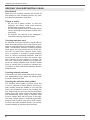
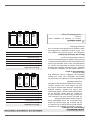
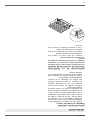
Step 4: minimum fl ame adjustment
WARNING!
These adjustments should be made only for use
of the appliance with natural gas. For use with li-
quid propane gas, the choke screw must be fully
turned in a clockwise direction.
SURFACE BURNERS
Light one burner at a time and set the knob to the
MINIMUM position (small fl ame).
Remove the knob.
The rangetop is equipped with a safety valve.
Using a small-size slotted screwdriver, locate the
choke valve on the valve body and turn the choke
screw to the right or left until the burner fl ame is
adjusted to desired minimum.
Make sure that the fl ame does not go out when
switching quickly from the MAXIMUM to the MINI-
MUM position.
For the gas valve of dual burner the choke valve is
located on the valve body, the A screw adjust the
outer ring, the B screw adjust the inner ring.
/ Gas conversion
yellow fl ames:
further adjustment is required
yellow tips on outer cones:
normal for LP gas
soft blue fl ames:
normal for natural gas
A
B

18
INSTALLATION CHECKLIST FINAL PREPARATION
A qualifi ed installer should carry out the following
checks:
Island trim or Backguard attached accor-
ding to instruction
Clearance to cabinet surfaces as manu-
facturer’s guideline
Proper ground connection
Gas service line connected following ma-
nufacturer’s guideline
Valves, stoppers and gasket installed
between the rangetop and the service line
Gas connection tested and free of gas
leaks
Rangetop settled for the type of gas avai-
lable in the household
Each burner lights satisfactorily, both indi-
vidually and with other burners operating
Flame appear sharp blue, with no yellow
tipping, shooting or fl ame lifting
Minimum settled for all burners
• Before using the rangetop, remove any
protective wrap from the stainless steel.
• All stainless steel body parts should be wiped
with hot, soapy water and with a liquid stainless
steel cleanser.
• If buildup occurs, do not use steel wool,
abrasive cloths, cleaners, or powders!
• If it is necessary to scrape stainless steel to
remove encrusted materials, soak with hot,
wet cloths to loosen the material, then use a
wood or nylon scraper.
• Do not use a metal knife, spatula, or any other
metal tool to scrape stainless steel! Scratches
are almost impossible to remove..
/ Installation checklist / fi nal preparation / Bertazzoni service
BERTAZZONI SERVICE
Bertazzoni is committed to providing the best cu-
stomer and product service. We have a dedicated
team of trained professionals to answer your ne-
eds.
If you own a Bertazzoni appliance and need ser-
vice in the US or Canada please use the following
contact information:
e-mail: [email protected]
Telephone - Monday through Friday,
7.30am to 7.30pm EST (except US public holidays).
US 866-905-0010
WESTERN CANADA 866-905-0010 (BC,AB,SK,MB)
EASTERN CANADA 800-561-7265 (ON,QC,NL,NB,NS,PE)

19
/User
BERTAZZONI
USER MANUAL
GAS RANGETOP

20
WARNINGS
Warning and Important Safety Instructions ap-
pearing in this manual are not meant to cover all
possible conditions and situations that may occur.
Common sense, caution, and care must be exer-
cised when installing, maintaining, or operating
the appliance.
Read and follow all instructions before using
this appliance to prevent the potential risk of
fi re, electric shock, personal injury or damage
to the appliance as a result of improper usage
of the appliance. Use appliance only for its in-
tended purpose as described in this manual.
Save this Manual for local electrical inspector’s
use. Read and save these instructions for future
reference. Observe all governing codes, ordinan-
ces and regulations.
WARNING!
If the information in these instructions is not fol-
lowed exactly, a fi re or explosion may result cau-
sing property damage, personal injury or death.
- Do not store or use gasoline or other fl ammable
vapors and liquid in the vicinity of this or any
other appliance.
- WHAT TO DO IF YOU SMELL GAS
• Do not try to light any appliance.
• Do not touch any electrical switch.
• Do not use any phone in your building.
• Immediately call your gas supplier from a
neighbor’s phone. Follow the gas sup-
plier’s instructions.
• If you cannot reach your gas suppliers,
call the fi re department.
- Installation and service must be performed by
a qualifi ed installer, service agency or the gas
supplier
In Massachusetts:
All gas products must be installed by a “Massa-
chusetts” licensed plumber or gasfi tter. A “T” han-
dle type manual gas valve must be installed in the
gas line connected to this appliance.
To ensure proper and safe operation: Appliance
must be properly installed and grounded by a qua-
lifi ed technician. DO NOT attempt to adjust, repair,
service, or replace any part of your appliance un-
less it is specifi cally recommended in this manual.
All other servicing should be referred to a qualifi ed
servicer. Have the installer show you the location
of the gas shut-off valve and how to shut it off in
an emergency.
A certifi ed technician is required for any adjust-
ments or conversions to Natural or LP gas.
To Prevent Fire or Smoke Damage
• Be sure all packing materials are removed
from the appliance before operating it.
• Never let clothing, potholders, or other
fl ammable materials come in contact with or
too close to any element, top burner or burner
grate until it has cooled.
• If appliance is installed near a window, proper
precautions should be taken to prevent
curtains from blowing over burners.
• Never leave any items on the cooktop. The
hot air from the vent may ignite fl ammable
items and may increase pressure in closed
containers which may cause them to burst.
• Many aerosol-type spray cans are EXPLOSIVE
when exposed to heat and may be highly
fl ammable. Avoid their use or storage near an
appliance.
In Case of Fire
Turn off appliance and ventilation hood to avoid
spreading the fl ame. Extinguish fl ame then turn
on hood to remove smoke and odor.
• Cooktop: Smother fi re or fl ame in a pan with a
lid or cookie sheet.
• NEVER pick up or move a fl aming pa
n.
Child Safety
• NEVER leave children alone or unsupervised
near the appliance when it is in use or is still
hot.
• NEVER allow children to sit or stand on any
part of the appliance as they could be injured
or burned.
• CAUTION do not store items of interest to
children in cabinets above the rangetop or
on the backguard of the rangetop. Children
climbing on the rangetop to reach those items
could be seriously injured.
/User Wrarning
La page est en cours de chargement...
La page est en cours de chargement...
La page est en cours de chargement...
La page est en cours de chargement...
La page est en cours de chargement...
La page est en cours de chargement...
La page est en cours de chargement...
La page est en cours de chargement...
La page est en cours de chargement...
La page est en cours de chargement...
La page est en cours de chargement...
La page est en cours de chargement...
La page est en cours de chargement...
La page est en cours de chargement...
La page est en cours de chargement...
La page est en cours de chargement...
La page est en cours de chargement...
La page est en cours de chargement...
La page est en cours de chargement...
La page est en cours de chargement...
La page est en cours de chargement...
La page est en cours de chargement...
La page est en cours de chargement...
La page est en cours de chargement...
La page est en cours de chargement...
La page est en cours de chargement...
La page est en cours de chargement...
La page est en cours de chargement...
La page est en cours de chargement...
La page est en cours de chargement...
La page est en cours de chargement...
La page est en cours de chargement...
La page est en cours de chargement...
La page est en cours de chargement...
La page est en cours de chargement...
La page est en cours de chargement...
La page est en cours de chargement...
La page est en cours de chargement...
La page est en cours de chargement...
La page est en cours de chargement...
-
 1
1
-
 2
2
-
 3
3
-
 4
4
-
 5
5
-
 6
6
-
 7
7
-
 8
8
-
 9
9
-
 10
10
-
 11
11
-
 12
12
-
 13
13
-
 14
14
-
 15
15
-
 16
16
-
 17
17
-
 18
18
-
 19
19
-
 20
20
-
 21
21
-
 22
22
-
 23
23
-
 24
24
-
 25
25
-
 26
26
-
 27
27
-
 28
28
-
 29
29
-
 30
30
-
 31
31
-
 32
32
-
 33
33
-
 34
34
-
 35
35
-
 36
36
-
 37
37
-
 38
38
-
 39
39
-
 40
40
-
 41
41
-
 42
42
-
 43
43
-
 44
44
-
 45
45
-
 46
46
-
 47
47
-
 48
48
-
 49
49
-
 50
50
-
 51
51
-
 52
52
-
 53
53
-
 54
54
-
 55
55
-
 56
56
-
 57
57
-
 58
58
-
 59
59
-
 60
60


Bertazzoni MAST366RTBXT Manuel utilisateur
- Catégorie
- Plaques électriques
- Taper
- Manuel utilisateur
dans d''autres langues
- English: Bertazzoni MAST366RTBXT User manual
Documents connexes
-
Bertazzoni PROF366QBXT Le manuel du propriétaire
-
Bertazzoni PRO486BTFGMXT Le manuel du propriétaire
-
Bertazzoni Freestanding Dual Fuel Ranges Manuel utilisateur
-
Bertazzoni PROF244GASXELP Guide d'installation
-
Bertazzoni PROF305CTXV Guide d'installation
-
Bertazzoni MAST305GASXE Le manuel du propriétaire
-
Bertazzoni MAST366GASXT Use & Care Full Gas Ranges
-
Bertazzoni MAST365DFMXE Installation Manual Electric oven ranges
-
Bertazzoni PMB24300X DL 3814ef7ded5cdf2993de413ba572
-
Bertazzoni KCH30XV Manuel utilisateur