Delta FVS2786701-SS Guide d'installation
- Catégorie
- Articles sanitaires
- Taper
- Guide d'installation

92345 Rev. E
MultiChoice
®
Valve Trim with Diverter
Installation Instructions
Owners Manual
T27859, T27867, T27897,
T27899, T27959, T27967,
T27997 & T27999
Series
Write purchased model number here.
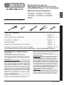
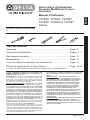
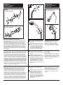
You May Need
THIS VALVE MEETS OR EXCEEDS THE
FOLLOWING STANDARDS: ASME A112.18.1/
CSA B125.1 and ASSE 1016 (Type -P- or -T-).
CAUTION: This system/device must be set by the
installer to ensure safe, maximum temperature.
Any change in the setting may raise the discharge
temperature above the limit considered safe and
may lead to hot water burns.
NOTICE TO INSTALLER: CAUTION!–As the
installer of this valve, it is your responsibility
to properly INSTALL and ADJUST this valve
per the instructions given. This valve does
not automatically adjust for inlet temperature
changes, therefore, someone must make the
necessary Rotational Limit Stop adjustments
at the time of installation and further adjustments
may be necessary due to seasonal water
temperature change. YOU MUST inform the
owner/user of this requirement by following
the instructions. If you or the owner/user are
unsure how to properly make these adjustments
please refer to page 6 and if still uncertain, call
us at 1-800-345-DELTA.
After installation and adjustment, you must afx
your name, company name and the date you
adjusted the Rotational Limit Stop to the caution
label provided and apply or attach the label to
the back side of the closest cabinet door and the
warning label to the water heater. Leave this
Instruction Sheet for the owner’s/user’s
reference.
WARNING: This pressure balanced or
thermostatic bath valve is designed
to minimize the effects of outlet water
temperature changes due to inlet pressure
changes, commonly caused by dishwashers,
washing machines, toilets and the like. It may
not provide protection from hot water burns
when there is a failure of other temperature
controlling devices elsewhere in the
plumbing system, if the rotational limit stop
is not properly set or if the hot water
temperature is changed after the settings are
made or if the water inlet changes
due to seasonal changes.
WARNING: Do not install a shut-off device on
either outlet of this valve. When this type of
device shuts off the water ow, it can defeat
the ability of the valve to balance the hot and
cold water pressures.
1
92345
Table of Contents:
Warranties ............................................................................... Page 2
Installation Instructions ........................................................... Pages 3 - 7
Clean and care......................................................................... Page 9
Maintenance ............................................................................ Page 9
Cartridge Summary Reference Sheet ..................................... Page 9
Classic Series Replacement Parts .......................................... Page 10-12
For additional replacement parts, visit www.deltafaucet.com
08/06/2018
3/32"

92345 Rev. E
2
Parts and Finish
All parts (other than electronic parts and batteries) and finishes of this Delta
®
faucet are warranted to the original consumer purchaser to be free from
defects in material and workmanship for as long as the original consumer purchaser owns the home in which the faucet was first installed or, for com-
mercial users, for 5 years from the date of purchase.
Electronic Parts and Batteries (if applicable)
Electronic parts (other than batteries), if any, of this Delta
®
faucet are warranted to the original consumer purchaser to be free from defects in material
and workmanship for 5 years from the date of purchase or, for commercial users, for one year from the date of purchase. No warranty is provided on
batteries.
Delta Faucet Company will replace, FREE OF CHARGE, during the applicable warranty period, any part or finish that proves defective in material and/
or workmanship under normal installation, use and service. If repair or replacement is not practical, Delta Faucet Company may elect to refund the
purchase price in exchange for the return of the product. These are your exclusive remedies.
Delta Faucet Company recommends using a professional plumber for all installation and repair. We also recommend that you use only genuine Delta
®
replacement parts.
Delta Faucet Company shall not be liable for any damage to the faucet resulting from misuse, abuse, neglect or improper or incorrectly performed
installation, maintenance or repair, including failure to follow the applicable care and cleaning instructions.
Replacement parts may be obtained by calling the applicable number below or by writing to:
In the United States and Mexico: In Canada:
Delta Faucet Company Masco Canada Limited, Plumbing Group
Product Service Technical Service Centre
55 E. 111th Street 350 South Edgeware Road
Indianapolis, IN 46280 St. Thomas, Ontario, Canada N5P 4L1
1-877-345-DELTA (3358) 1-877-345-DELTA (3358)
Proof of purchase (original sales receipt) from the original purchaser must be made available to Delta Faucet Company for all warranty claims unless
the purchaser has registered the product with Brizo Kitchen & Bath Company. This warranty applies only to Delta
®
faucets manufactured after January
1, 1995 and installed in the United States of America, Canada and Mexico.
DELTA FAUCET COMPANY SHALL NOT BE LIABLE FOR ANY SPECIAL, INCIDENTAL OR CONSEQUENTIAL DAMAGES (INCLUDING LABOR
CHARGES) FOR BREACH OF ANY EXPRESS OR IMPLIED WARRANTY ON THE FAUCET. Some states/provinces do not allow the exclusion or lim-
itation of special, incidental or consequential damages, so these limitations and exclusions may not apply to you. This warranty gives you special legal
rights. You may also have other rights which vary from state/province to state/province.
This is Delta Faucet Company’s exclusive written warranty and the warranty is not transferable.
If you have any questions or concerns regarding our warranty, please view our Warranty FAQs at www.deltafaucet.com, email us at customerservice@
deltafaucet.com or call us at the applicable number above.
Lifetime Faucet and Finish Limited Warranty
© 2018 Masco Corporation of Indiana

92345 Rev. E
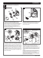
Installation
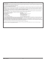
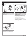
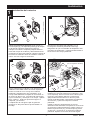
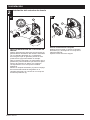
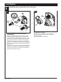
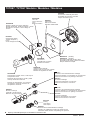
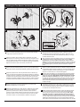
1
Cartridge Installation
A.
B.
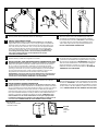
Turn off water supplies. Remove cover (1),
bonnet nuts (2) and test caps (3) from the
rough-in body (4).
Place a bucket or small container over the front
of the valve body and slowly open the water
supplies to ush any debris from the supply
lines before installing the cartridge. Turn the
water supplies back off.
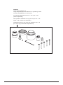
Insert adapter assembly (1) into rough-in
body (2). Make sure the adapter assembly
is correctly positioned and is pressed all
the way down inside rough-in body.
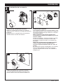
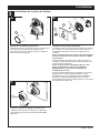
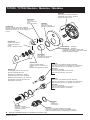
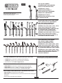
Rotate cartridge (1) so the words “HOT SIDE”
(2) appear on the left. Insert cartridge assembly
into rough-in body. Make sure the key (3) on the
valve cartridge is fully engaged with the slot in
the brass body (4). Insert bonnet nut (5) over
the cartridge and thread onto the body. Hand
tighten securely, slide o-ring (6) over bonnet
and cartridge. A light coating of plumbers
grease applied to o-rings may aid in assembly.
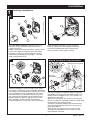
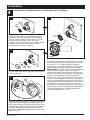
For the exceptions of back to back or reverse
installations (hot on right and cold on left) only:
Rotate valve cartridge (1) so “HOT SIDE” (2)
appears on the right.
Apply silicone lube to the three o-rings shown
above to make the cartridge easier to install and
remove from the rough-in body.
Install the cartridge making sure that the keys
are fully engaged with the slot in the rough-in
body (see step C).
Slide o-ring (3) and bonnet nut (4) over the
cartridge and thread onto the rough-in body.
Hand tighten securely.
3
C.
Back to back Installation
Normal Installation
(changes not required)
Reverse
Installation
Cold
Hot
1
2
3
4
2
3
1
2
1
2
3
4
5
3
4
2
4
3
1
6

92345 Rev. E
Installation
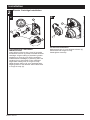
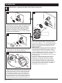
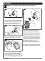
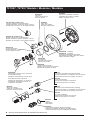
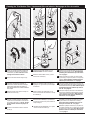
2
Diverter Cartridge Installation
4
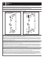
For Bonnet Installation
Slide bonnet nut (1) over diverter sleeve (2)
and thread into rough-in body.
Hand tighten securely.
B.
FOR DIVERTER CARTRIDGE
INSTALLATION:
Apply silicone lube to the o-ring (2) to make
the diverter sleeve (3) easier to install diverter
cartridge. A light coating of plumbers grease
applied to o-rings (4) may aid in assembly.
Install diverter cartridge (1) assuring that the
locating pin on the bottom of the cartridge
aligns with mating hole in rough-in body.
Slide diverter sleeve (3) over cartridge stem
aligning tabs on the diverter sleeve with slots
in rough-in body (5).
A.
3
1
5
2
1
2
5
4

92345 Rev. E
Installation
3
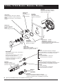
5
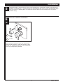
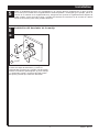
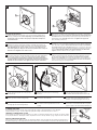
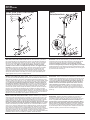
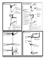
Trim Installation
Trim Sleeve Installation
Slide trim sleeve (1) over the bonnet (2),
cartridge and rough-in body.
Ensure sleeve is properly positioned over the
front of cartridge.
Escutcheon Installation
For nished wall thickness up to 1 1/8". Secure
the backplate (1) to the rough-in body (2) using
4 screws (3) provided.
Note: Be sure backplate is oriented front side
forward and markings are visible.
Slide escutcheon (4) over diverter cartridge,
thread trim nut (5) onto diverter sleeve (6).
Note: For thick wall installations, order
installation kit RP90543 to support nished
wall thickness up to 2 1/8".
On rough or uneven surfaces it is necessary
to apply caulk around the backplate (1) to
supplement the seal. Do not caulk the drip notch
in the bottom of the backplate (1). Do not caulk
the escutcheon (4).
1
2
A. B.
1
2
5
4
C.
1
Install volume control handle (1) with lever
pointing down, then turn to the on position.
DO NOT SECURE WITH SCREW.
3
3
6
Drip notch

92345 Rev. E
Installation
4
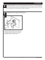
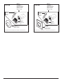
6
Installation and Adjustment of the Rotational Limit Stop
A.
B.
Place the rotational limit stop (1) in
volume
handle (2) and rotate to the mixed
position (if
required). DO NOT SECURE WITH
SCREW.
Turn on water supplies; let the
water
run until
both hot and cold water is as hot/
cold as
possible. Place thermometer in a plastic tumbler,
and hold the tumbler in the water stream.
Record the temperature reading.
If the water temperature is above 120°F, remove
and rotate the limit stop (1) clockwise one tooth
for every 4°F - 6°F (approximate) change in
temperature. If water temperature is cooler than
desired, rotate the limit stop counterclockwise.
IMPORTANT: The rst position of the Rotational
Limit Stop (the Limiter) is the position that
restricts the rotation of the stem the most and is
at the maximum clockwise setting. According to
industry standards, the maximum allowable
temperature of the water exiting from the valve is
120
o
F. This temperature may vary in your local
area. The Rotational Limit Stop may need to be
readjusted if the inlet water temperature changes.
For instance, during the winter, the cold water
temperature is colder than it is during the summer
which could result in varying outlet temperatures.
Typical temperature for a comfortable bath or
shower is between 90
o
–110
o
F.
C.
Hotter
Colder
Secure temperature control knob (1) with screw
(2). See next step (D) for securing temperature
control cover (3).
Snap temperature control cover over temperature
control knob by rst aligning smaller tab (1) on
cover with receiving slot (2) on temperature knob.
Swing larger tab (3) to engage with snap feature
(4). Note: If dis-assembly is required, reverse
this motion, disengaging larger tab (3) from snap
feature (4) rst.
1
1
1
2
3
2
D.
4
2
1
3

92345 Rev. E
Potential scald or thermal shock injury could result due to cross ow if outlet at the shower is
blocked or restricted (e.g., pause control on showerhead). Be sure to point showerhead away
from you when re-starting ow or install inlet check valves on both supply lines to prevent
possible injury.
7
6
Diverter handle Installation
Diverter Handle Installation
Slide diverter handle (1) onto trim sleeve (2).
Using a allen wrench, insert set screw (3) into
handle (1). Applying pressure, insert set screw
cover (4) until properly seated.
B.
2
1
3
4
Installation
5

92345 Rev. E
8
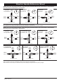
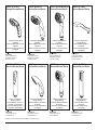
Diverter Handle Reference Sheet
2nd Position
2 ª Posición
2e position
3rd Position
3 ª posición
3e position
1st Position
1 ª posición
1ère position
2nd Position
2 ª Posición
2e position
3rd Position
3 ª posición
3e position
Outlet 1
Salida 1
Sortie 1
Outlet 2
Salida 2
Sortie 2
Outlet 3
Salida 3
Sortie 3
In / Entrada / Entrée
4th Position
4 ª posición
4e position
5th Position
5 ª posición
5e position
6th Position
6 ª posición
6e position
Water Flow For 3 Function Diverter / Flujo de agua para Desviadores de 3 posiciones / Écoulement
de l’eau pour les inverseurs à 3 positions
Water Flow For 6 Function Diverter / Flujo de agua para Desviadores de 6 posiciones / Écoulement
de l’eau pour les inverseurs à 6 positions
In / Entrada / Entrée In / Entrada / Entrée
In / Entrada / Entrée
In / Entrada / Entrée
In / Entrada / Entrée
Outlet 1
Salida 1
Sortie 1
Outlet 2
Salida 2
Sortie 2
Outlet 3
Salida 3
Sortie 3
Outlet 1
Salida 1
Sortie 1
Outlet 2
Salida 2
Sortie 2
Outlet 3
Salida 3
Sortie 3
Outlet 1
Salida 1
Sortie 1
Outlet 2
Salida 2
Sortie 2
Outlet 3
Salida 3
Sortie 3
Outlet 1
Salida 1
Sortie 1
Outlet 2
Salida 2
Sortie 2
Outlet 3
Salida 3
Sortie 3
Outlet 1
Salida 1
Sortie 1
Outlet 2
Salida 2
Sortie 2
Outlet 3
Salida 3
Sortie 3
Outlet 1
Salida 1
Sortie 1
Outlet 2
Salida 2
Sortie 2
Outlet 3
Salida 3
Sortie 3
Outlet 1
Salida 1
Sortie 1
Outlet 2
Salida 2
Sortie 2
Outlet 3
Salida 3
Sortie 3
Outlet 1
Salida 1
Sortie 1
Outlet 2
Salida 2
Sortie 2
Outlet 3
Salida 3
Sortie 3
In / Entrada / Entrée
In / Entrada / Entrée
In / Entrada / Entrée
Shared positions do not exist in non-shared cartridges.
Los ajustes o posiciones compartidas no existen en los cartuchos no-compartidos.
Comme leur nom l’indique, les cartouches sans position partagée ne comportent aucune position partagée.
Shared positions do not exist in non-shared cartridges.
Los ajustes o posiciones compartidas no existen en los cartuchos no-compartidos.
Comme leur nom l’indique, les cartouches sans position partagée ne comportent aucune position partagée.
1st Position
1 ª posición
1ère position

92345 Rev. E
Clean and Care
Care should be given to the cleaning
of this product. Although its nish is
extremely durable, it can be damaged by
harsh abrasives or polish. To clean, simply
wipe gently with a damp cloth and blot dry
with a soft towel.
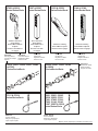
Maintenance
Faucet leaks from showerhead:
SHUT OFF WATER SUPPLIES.
Replace valve cartridge
RP46463 or RP32104
See Helpful Hints 1, 2, 3 & 4.
Helpful Hints:
1. Before removing valve cartridge assembly for any
maintenance, be sure to note the position of the
rotational limit stop on the cap. The valve cartridge
assembly must always be put back in the same
position. BE SAFE! After you have nished the
installation, turn on valve to make sure COLD
WATER FLOWS FIRST.
2. To remove valve cartridge from body, shut off
water supplies and remove handle and bonnet nut.
Do not pry the valve cartridge out of the body with
a screwdriver. Place handle on stem and rotate
counterclockwise approximately 1/4 turn after the
stop has been contacted. Lift valve cartridge out
of body.
Remove seats and springs and replace.
Place the largest diameter of the spring into the
seat pocket rst and then press the tapered end
of the seal over the spring. Reassemble valve
cartridge and replace in body following instructions
given in 1 above.
3. If the water in your area has lime, rust, sand
or other contaminants in it, your pressure
balance valve will require periodic inspection.
The frequency of the inspection will depend
on the amount of contaminants in the water. To
inspect valve cartridge remove it and follow the
steps in note 1 above. Turn the valve to the full
mix position and shake the cartridge vigorously.
If there is a rattling sound, the unit is functional
and can be reinstalled following instructions given
in note 1 above. If there is no rattle, replace the
housing assembly with the proper RP.
Cartridge Summary Reference Sheet
Order RP46463 to
Replace Cartridge.
Grey Upper Cap
V Notch
Adapter
Shorter Tab
T27
9

92345 Rev. E

92345 Rev. E
Instrucciones para la
instalación del Accesorio de la
VálvulMultiChoice
®
con desviador
Manual para propietarios
T27859, T27867, T27897,
T27959, T27967 & T27997
Serie
Escriba el número del modelo aquí.
Puede necesitar
ESTA VALVULA cumple o excede las siguientes
normas: ASME A112.18.1 / CSA B125.1 y ASSE 1016
(Tipo -P- o -T-).
ADVERTENCIA: Este sistema/dispositivo debe
congurarse por el instalador para asegurar una
temperatura máximo segura. Cualquier cambio en el ajuste
puede aumentar la temperatura de salida por encima del
límite considerado seguro y puede dar lugar a quemaduras
por agua caliente.
AVISO PARA EL INSTALADOR: ¡ATENCIÓN! -Como
el instalador de esta válvula, es su responsabilidad
de INSTALAR y AJUSTAR correctamente esta válvula
según las instrucciones proporcionadas. Esta válvula
no se ajusta automáticamente a los cambios de
temperatura de entrada, por lo tanto, alguien debe
hacer los ajustes necesarios al Tope del Límite
Rotacional en el momento de la instalación y ajustes
adicionales pueden ser necesarios debido a cambios
estacionales de la temperatura del agua. USTED
DEBE informar al propietario/usuario de este requisito
siguiendo las instrucciones. Si usted o el dueño/
consumidor no está seguro de como hacer estos ajustes,
por favor consulte la página 6 y si aún tiene duda,
llámenos al 1-800-345-DELTA.
Después de la instalación y el ajuste, debe colocar su
nombre, nombre de la empresa y la fecha en que ajustó la
perilla de control de la temperatura a la etiqueta de
precaución proporcionada y aplique o pegue la etiqueta en
la parte trasera de la puerta del armario más cercano y la
etiqueta de advertencia al calentador de agua.
Deje esta hoja de instrucciones para referencia del
propietario /usuario.
ADVERTENCIA: Esta válvula termostática de baño está
diseñada para minimizar los efectos de los cambios
de temperatura del agua de salida debido a cambios
de presión y temperatura, causados habitualmente
por los lavaplatos, las lavadoras, los inodoros y otros
aparatos similares. Puede no ofrecer protección contra
las quemaduras por agua caliente cuando hay un fallo
de otros dispositivos para el control de temperatura
en otras partes del sistema de plomería, si el Tope del
Límite Rotacional no está congurado correctamente
o si se cambia la temperatura del agua caliente
después de realizar los ajustes o si el agua admisión
cambia debido a los cambios estacionales.
ADVERTENCIA: No instale un dispositivo de cierre en
cualquiera de las tuberías de salida de agua de esta
válvula. Cuando este tipo de dispositivo cierra el ujo
del agua, pueda aminorar el propósito de la válvula
para balancear las presiones del agua caliente y fría.
08/06/2018 1
92345
Tabla de contenido:
Garantía ............................................................................... Página 2
Instrucciones de instalación ................................................ Páginas 3 - 7
Limpieza y cuidado .............................................................. Página 9
Mantenimiento ...................................................................... Página 9
Hoja de referencia para el Cartucho .................................... Página 9
Piezas de repuesto para la serie Classic ............................. Página 10-12
Para obtener piezas de repuesto adicionales, visite www.deltafaucet.com

92345 Rev. E
2
Piezas y Acabado
Todas las piezas (menos las piezas electrónicas y las pilas) y acabados de esta llave de agua - grifo Delta® están garantizados al consumidor com-
prador original, de estar libres de defectos en materiales y mano de obra durante el tiempo que el comprador original sea dueño de la casa en la cual
la llave de agua fue instalada por primera vez o, para los usuarios comerciales, por cinco (5) años desde la fecha de compra.
Piezas electrónicas y las baterías/pilas (si aplicable)
Las piezas electrónicas (excepto las baterías), sea el caso, de este grifo Delta® están garantizadas al consumidor comprador original, de estar libres
de defectos en materiales y mano de obra durante 5 años desde la fecha de compra o, para los usuarios comerciales, durante un año desde la fecha
de compra. La garantía no cubre las baterías.
Delta Faucet Company reparará o reemplazará, SIN COSTO ALGUNO, durante el período de garantía aplicable, cualquier pieza o acabado que
presente defectos en materiales y/o mano de obra bajo instalación, uso y servicio normal. Si la reparación o sustitución no es práctica, Delta Faucet
Company podrá optar reintegrarle el precio de la compra a cambio de la devolución del producto. Estos son sus únicos recursos.
Delta Faucet Company recomienda que use un plomero profesional para todas las instalaciones y reparación. También recomienda que utilice sólo
piezas de repuesto Delta
®
.
Delta Faucet Company no será responsable de cualquier daño a la llave de agua/grifo resultante del uso indebido, abuso, negligencia o uso ina-
propiado o instalación realizada de forma incorrecta, mantenimiento o reparación, incluyendo el no seguir las instrucciones de cuidado y limpieza
aplicables.
Las piezas de repuesto se pueden obtener llamando al número que figura más abajo o escribiendo a:
En los Estados Unidos y Mexico: En Canadá:
Delta Faucet Company Masco Canada Limited, Plumbing Group
Product Service Technical Service Centre
55 E. 111th Street 350 South Edgeware Road
Indianapolis, IN 46280 St. Thomas, Ontario, Canada N5P 4L1
1-877-345-DELTA (3358) 1-877-345-DELTA (3358)
La prueba de compra (recibo original de venta) del comprador original debe ponerse a la disposición de Delta Faucet Company para todos los reclam-
os de garantía a menos que el comprador haya registrado el producto con Delta Faucet Company. Esta garantía se aplica solamente a las llaves de
agua/grifos Delta
®
fabricadas después de 1 de enero de 1995 e instalados en los Estados Unidos de América, Canadá y México.
DELTA FAUCET COMPANY NO SERÁ RESPONSABLE POR DAÑOS ESPECIALES, INCIDENTALES O CONSECUENTES (INCLUYENDO
CARGOS DE LABOR) YA SEAN RESULTANTES DEL INCUMPLIMIENTO DE CUALQUIER GARANTÍA EXPRESA O IMPLÍCITA DE LA LLAVE DE
AGUA/GRIFO. Algunos estados/provincias no permiten la exclusión o limitación de daños especiales, incidentales o consecuentes, por lo que estas
limitaciones y exclusiones pueden no aplicarle en su caso.
Esta garantía le otorga derechos legales especiales, y usted también puede tener otros derechos que varían de estado/provincia a estado/provincia.
Esta es la garantía exclusiva por escrito de Delta Faucet Company’s, y la garantía no es transferible.
Si usted tiene alguna pregunta o inquietud acerca de nuestra garantía, por favor vea nuestra sección de Preguntas Frecuentes sobre la garantía www.deltafau-
cet.com, email us at [email protected].
Garantía limitada de por vida de la llave de agua y acabado
© 2018 Masco Corporación of Indiana

92345 Rev. E
Instalación
1
Instalación del cartucho
A.
B.
Cierre los suministros de agua. Quite la tapa (1),
tuercas tapas (2) y las tapas de prueba (3) del cuerpo
de la tubería preliminar detrás de la pared (4).
Coloque una cubeta o recipiente pequeño sobre el
frente del cuerpo de la válvula y abra lentamente los
suministros de agua para eliminar cualquier residuo de
las líneas de suministro antes de instalar el cartucho.
Cierre otra vez el agua de suministro.
Introduzca el ensamble del adaptador (1) en
el cuerpo de la tubería preliminar interna (2).
Asegúrese de que el ensamble del adaptador está
colocado correctamente y está presionado hasta el
fondo dentro del cuerpo preliminar.
Gire el cartucho de la válvula (1) de forma que las
palabras "HOT SIDE" estén en el lado izquierdo.
Inserte el cartucho en el cuerpo de la tubería
preliminar. Asegúrese de que el dentado en el
cuerpo está totalmente encajado en la muesca en
el cuerpo de bronce (4). Introduzca la tuerca tapa
(5) en el cartucho y enrosque en el cuerpo. Apriete
bien, a mano y deslice la junta tórica (6) en el
casquete y el cartucho.
La aplicación de una ligera capa de grasa de
plomeros en las juntas tóricas puede facilitar el
montaje.
Solo para las excepciones de dorso con dorso o
instalaciones inversas (caliente en la derecha y fría
en la izquierda): Gire el cartucho de la válvula (1) de
forma que "HOT SIDE" aparece en la derecha.
Aplique lubricante de silicona en las tres juntas
tóricas mostradas arriba para facilitar la instalación
del cartucho y quitar del cuerpo de la tubería
preliminar.
Instale el cartucho asegurándose de que los
dentados están totalmente encajados en la ranura en
el cuerpo de la tubería preliminar (véase el paso C).
Deslice la junta tórica (3) y la tuerca tapa (4) sobre
el cartucho y enrosque en el cuerpo de la tubería
preliminar. Apriete con la mano de forma segura.
3
C.
Instalación de dorso con dorso.
Instalación normal
(no se requieren cambios)
Reverse
Installation
Cold
Hot
1
2
3
4
2
3
1
2
1
2
3
4
5
3
4
2
4
3
1
6

92345 Rev. E
Instalación
2
Instalación del cartucho de desvío
4
Para la instalación del casquete
Deslice la tuerca tapa (1) sobre el casquillo
desviador (2) y enrosque en el cuerpo de la
tubería preliminar.
Apriete a mano de forma segura.
B.
PARA LA INSTALACIÓN DEL CARTUCHO DE
DESVÍO:
Aplique lubricante de silicona a la junta tórica (2)
para facilitar la instalación del cartucho desviador
con el casquillo desviador (3). La aplicación
de una ligera capa de grasa de plomeros a las
juntas tóricas (4) puede facilitar el montaje.
Gire el cartucho desviador (1) asegurando que el
pasador de posicionamiento que está en la parte
inferior del cartucho se alinee con el agujero
correspondiente en el cuerpo de la tubería
preliminar.
Deslice el casquillo desviador (3) sobre la espiga
del cartucho alineando las lengüetas en el
casquillo desviador con ranuras en el cuerpo de
la tubería preliminar (5).
A.
3
1
5
2
1
2
5
4

92345 Rev. E
Instalación
3
5
Instalación del accesorio
Instalación del casquillo del accesorio
Deslice el casquillo del accesorio (1) sobre el
casquete (2), el cartucho y el cuerpo de la tubería
preliminar.
Asegúrese que el casquillo está correctamente
colocado sobre el frente del cartucho.
Instalación del chapetón
Para paredes acabadas de un grosor hasta 1 1/8".
Fije la placa posterior (1) al cuerpo de la unidad de
las tuberías preliminares (2) usando los 4 tornillos
(3) proporcionados.
Nota: asegúrese que la placa trasera está
colocada con el frente hacia adelante y con las
marcas visibles.
Deslice el chapetón o chapa de cubierta (4) sobre
el cartucho desviador, enrosque la tuerca del
accesorio (5) proporcionada en el casquillo del
desviador.
Nota: para instalaciones en paredes gruesas,
ordene el juego de piezas RP90543 para
sostener la pared acabada hasta de 2 1/8" de
grosor.
En supercies rugosas o desiguales, es necesario
aplicar masilla alrededor de la placa posterior
(1) para complementar el sello. No calafatee el
chapetón (4).
1
2
A. B.
1
2
5
4
C.
1
Instale la manija para el control de; volumen
(1) con la palanca hacia abajo, luego gire a la
posición abierta. NO FIJE CON EL TORNILLO.
3
3

92345 Rev. E
Instalación
4
6
Instalación y ajuste del tope del límite rotacional
B.
Coloque la perilla para el control de temperatura (1)
en la palanca de volumen y gire a la posición mixta
(si es necesario). NO FIJE CON EL TORNILLO.
Abra los suministros de agua; deje que el agua
uya hasta que esté lo más caliente/fría posible.
Coloque un termómetro en un vaso plástico, y
sostenga el vaso bajo el chorro de agua. Registre
la lectura de la temperatura.
Si la temperatura del agua está por encima de
120° F, retire y gire el tope (1) un diente hacia la
derecha por cada 4° F - 6° F (aproximadamente)
cambio en la temperatura. Si la temperatura del
agua es más fría que lo deseada, gire el tope
hacia la izquierda.
IMPORTANTE: La primera posición del Tope del
Límite Rotacional (el limitador) es la posición que
más restringe la rotación e la espiga y está en
el ajuste máximo hacia la derecha. De acuerdo
con los estándares de la industria, la temperatura
máxima permisible del agua que sale de la
válvula es 120° F. Esta temperatura puede variar
en su área local.
El Tope del Límite Rotacional puede requerir
reajuste si cambia la temperatura del agua
de entrada. Por ejemplo, durante el invierno,
la temperatura del agua fría es más fría de lo
que es durante el verano que podría resultar
en una variación de temperaturas de salida. La
temperatura típica para un baño o una ducha
confortable es entre 90o-110o F.
Hotter
Colder
Fije la perilla para el control de la temperatura (1)
con el tornillo (2). Para jar la tapa del control de
temperatura (3), vea el próximo paso (D).
1
A.
1
1
2
3
C.
Coloque a presión la tapa del control de temperatura sobre
el pomo del control de temperatura alineando primero la
lengüeta más pequeña (1) con la muesca para encajar
en la cubierta (2) ubicada en el pomo de temperatura.
Gire la lengúeta más grande (3) para que encaje con el
mecanismo de presión (4). Nota: Si requiere desarmar,
repita estos pasos en reverso, desencajando primero la
lengúeta más grande (3) del mecanismo de presión (4).
D.
4
2
1
3

92345 Rev. E
Existe la posibilidad de lesión por escaldadura o de choque térmico resultante de un ujo cruzado
en el caso que la salida de la regadera/ducha está bloqueada o restringida (por ejemplo, pause el
control de la cabeza de la regadera/ducha). Asegúrese de apuntar la regadera/ducha alejado de
usted cuando vuelva a iniciar el ujo o instale las válvulas de retención de la entrada en ambas
líneas de suministro para evitar posibles lesiones.
7
Instalación del desviador de la manija
Instalación del desviador de la manija
Inserte la manija del desviador (1) sobre el
casquillo del accesorio (2). Usando una llave allen,
inserte el tornillo de jación/ajuste (3) en la manija
(1). Aplicando presión, inserte la tapa del tornillo
de ajuste (4) hasta que esté bien asentada.
6
B.
2
1
3
4
Installation
5

92345 Rev. E
8
Hoja de referencia para la manija desviadora
2nd Position
2 ª Posición
2e position
3rd Position
3 ª posición
3e position
1st Position
1 ª posición
1ère position
2nd Position
2 ª Posición
2e position
3rd Position
3 ª posición
3e position
Outlet 1
Salida 1
Sortie 1
Outlet 2
Salida 2
Sortie 2
Outlet 3
Salida 3
Sortie 3
In / Entrada / Entrée
4th Position
4 ª posición
4e position
5th Position
5 ª posición
5e position
6th Position
6 ª posición
6e position
Water Flow For 3 Function Diverter / Flujo de agua para Desviadores de 3 posiciones / Écoulement
de l’eau pour les inverseurs à 3 positions
Water Flow For 6 Function Diverter / Flujo de agua para Desviadores de 6 posiciones / Écoulement
de l’eau pour les inverseurs à 6 positions
In / Entrada / Entrée In / Entrada / Entrée
In / Entrada / Entrée
In / Entrada / Entrée
In / Entrada / Entrée
Outlet 1
Salida 1
Sortie 1
Outlet 2
Salida 2
Sortie 2
Outlet 3
Salida 3
Sortie 3
Outlet 1
Salida 1
Sortie 1
Outlet 2
Salida 2
Sortie 2
Outlet 3
Salida 3
Sortie 3
Outlet 1
Salida 1
Sortie 1
Outlet 2
Salida 2
Sortie 2
Outlet 3
Salida 3
Sortie 3
Outlet 1
Salida 1
Sortie 1
Outlet 2
Salida 2
Sortie 2
Outlet 3
Salida 3
Sortie 3
Outlet 1
Salida 1
Sortie 1
Outlet 2
Salida 2
Sortie 2
Outlet 3
Salida 3
Sortie 3
Outlet 1
Salida 1
Sortie 1
Outlet 2
Salida 2
Sortie 2
Outlet 3
Salida 3
Sortie 3
Outlet 1
Salida 1
Sortie 1
Outlet 2
Salida 2
Sortie 2
Outlet 3
Salida 3
Sortie 3
Outlet 1
Salida 1
Sortie 1
Outlet 2
Salida 2
Sortie 2
Outlet 3
Salida 3
Sortie 3
In / Entrada / Entrée
In / Entrada / Entrée
In / Entrada / Entrée
Shared positions do not exist in non-shared cartridges.
Los ajustes o posiciones compartidas no existen en los cartuchos no-compartidos.
Comme leur nom l’indique, les cartouches sans position partagée ne comportent aucune position partagée.
Shared positions do not exist in non-shared cartridges.
Los ajustes o posiciones compartidas no existen en los cartuchos no-compartidos.
Comme leur nom l’indique, les cartouches sans position partagée ne comportent aucune position partagée.
1st Position
1 ª posición
1ère position

92345 Rev. E
Limpieza y Cuidado
Se debe tener cuidado con la limpieza de este producto.
Aunque su acabado es extremadamente resistente, puede
ser dañado por abrasivos o pulimentos ásperos. Para
limpiar, simplemente frote con un paño húmedo y seque con
una toalla suave.
Mantenimiento
Si hay ltración de agua desde la llave de agua/grifo de
la regadera:
CIERRE LOS SUMINISTROS DE AGUA. Reemplace la
válvula de cartucho o RP46463 RP32104
Vea Consejos útiles 1, 2, 3 y 4
Sugerencias útiles:
1. Antes de retirar el ensamble del cartucho de la válvula
para cualquier tarea de mantenimiento, asegúrese de anotar
la posición del tope de rotación en la tapa. El ensamble del
cartucho de la válvula siempre debe ser puesto de nuevo
en la misma posición. ¡CUIDESE! Después de que haya
terminado la instalación, abra la válvula para asegurarse de
que el agua FLUYE FRÍA PRIMERO.
2. Para extraer el cartucho de la válvula del cuerpo, cierre
el suministro de agua y retire la manija y la tuerca tapa. No
se debe quitar el cartucho de la válvula del cuerpo con un
destornillador. Coloque la manija en la espiga y gire hacia
la izquierda aproximadamente 1/4 de vuelta después que el
tope tenga contacto. Levante el cartucho de la válvula del
cuerpo.
Retire los asientos y resortes y reemplácelos.
Primero, coloque el diámetro mayor del resorte en el
bolsillo del asiento y luego presione el extremo cónico de
la junta sobre el resorte. Vuelva a ensamblar el cartucho
de la válvula y colóquelo de nuevo en el cuerpo, siguiendo
las instrucciones dadas en el punto 1.
3. Si el agua en su área contiene cal, óxido, arena u
otros contaminantes, su válvula de equilibrio de presión
requerirá una inspección periódica.
La frecuencia de la inspección dependerá de la cantidad
de contaminantes en el agua. Para inspeccionar el
cartucho de la válvula y quitarla y siga los pasos indicados
en la nota 1 anterior. Gire la válvula a la posición de
mezcla completa y agite el cartucho con fuerza.
Si hay un sonido de traqueteo, la unidad es funcional y se
puede volver a instalar siguiendo las instrucciones dadas
en la nota 1 anterior. Si no hay traqueteo, reemplace
el conjunto de la cubierta con la pieza de repuesto/RP
adecuada.
Hoja de resumen de referencia para el cartucho
Ordene RP46463 para
Reemplazar cartucho.
Tapa superior Gris
Muesca V
Adaptador
Lengüeta más corta
T27
9

92345 Rev. E
La page charge ...
La page charge ...
La page charge ...
La page charge ...
La page charge ...
La page charge ...
La page charge ...
La page charge ...
La page charge ...
La page charge ...
La page charge ...
La page charge ...
La page charge ...
La page charge ...
La page charge ...
La page charge ...
La page charge ...
La page charge ...
La page charge ...
La page charge ...
La page charge ...
La page charge ...
La page charge ...
La page charge ...
La page charge ...
La page charge ...
La page charge ...
La page charge ...
La page charge ...
La page charge ...
La page charge ...
La page charge ...
La page charge ...
La page charge ...
-
 1
1
-
 2
2
-
 3
3
-
 4
4
-
 5
5
-
 6
6
-
 7
7
-
 8
8
-
 9
9
-
 10
10
-
 11
11
-
 12
12
-
 13
13
-
 14
14
-
 15
15
-
 16
16
-
 17
17
-
 18
18
-
 19
19
-
 20
20
-
 21
21
-
 22
22
-
 23
23
-
 24
24
-
 25
25
-
 26
26
-
 27
27
-
 28
28
-
 29
29
-
 30
30
-
 31
31
-
 32
32
-
 33
33
-
 34
34
-
 35
35
-
 36
36
-
 37
37
-
 38
38
-
 39
39
-
 40
40
-
 41
41
-
 42
42
-
 43
43
-
 44
44
-
 45
45
-
 46
46
-
 47
47
-
 48
48
-
 49
49
-
 50
50
-
 51
51
-
 52
52
-
 53
53
-
 54
54


Delta FVS2786701-SS Guide d'installation
- Catégorie
- Articles sanitaires
- Taper
- Guide d'installation
dans d''autres langues
Documents connexes
-
Delta 55424-BL Guide d'installation
-
Delta T27867-SS Guide d'installation
-
-
-
-
Delta 50570-CZ Guide d'installation
-
-
-
-
Autres documents
-
Delta Faucet T27967 Guide d'installation
-
-
American Standard 131531 Guide d'installation
-
Danze D106900BT Mode d'emploi
-
-
Camco 8615833 Le manuel du propriétaire
-
-
-
Moen 197930 Le manuel du propriétaire
-