Powerfist 8509960 Le manuel du propriétaire
- Taper
- Le manuel du propriétaire

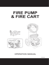
WATER, TRASH, CHEMICAL
TRANSFER PUMP
OPERATOR’S MANUAL
85.609.19706.20


3
Introduction ....................................................................
Product Identication .................................................
Safety alert and symbol meanings ..........................
Warning and hazards ...................................................
Water pump components ...........................................
Assembly of hoses .......................................................
Pump Operation and set up ......................................
Priming the pump .........................................................
Starting the engine and pump ..................................
Stopping the engine and cleaning pump ..............
High Altitude Replacement Kit ..................................
Warranty Statement ..................................................
4
5
6
7
11
12
13
15
16
18
19
20
TABLE OF CONTENTS

4
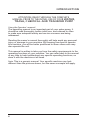
Using the Operator’s manual
The operating manual is an important part of your water pump. It
should be read thoroughly before initial use, and referred to often
to make sure adequate safety and service concerns are being
addressed.
Reading the owner’s manual thoroughly will help avoid any personal
injury or damage to your machine. By knowing how best to operate
this machine, you will be better positioned to show others who may
also operate the unit.
This manual is written to take you from the safety requirements to the
operating functions of your machine. You can refer back to the manual
at any time to help troubleshoot any specic operating functions, so
store it with the machine at all times.
Note: This is a generic manual. Your specic machine may look
dierent than the pictures shown, but the same concepts will apply.
ATTENTION: READ THROUGH THE COMPLETE
MANUAL PRIOR TO THE INITIAL USE OF YOUR WATER,
TRASH, CHEMICAL AND TRANSFER PUMP
INTRODUCTION

5
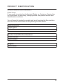
Record Identication Numbers
Water Pump
If you need to contact an Authorized Dealer or Customer Service line
for information on servicing, always provide the product model and
identication numbers.
You will need to locate the model and serial number for the machine
and record the information in the places provided below.
Date of Purchase:
Dealer Name:
Dealer Phone:
Product Identication Numbers
Model Number:
Serial Number:
Engine
Horse Power:
PRODUCT IDENTIFICATION

6
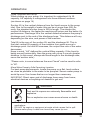
The safety alert symbol ( ) is used with a signal word (DANGER,
CAUTION, WARNING), a pictorial and/or a safety message to alert
you to hazards.
DANGER indicates a hazard which, if not avoided, will result in
death or serious injury.
WARNING indicates a hazard which, if not avoided, could result in
death or serious injury.
CAUTION indicates a hazard which, if not avoided, might result in
minor or moderate injury.
NOTICE indicates a situation that could result in equipment damage.
Follow safety messages to avoid or reduce the risk of injury or
death.
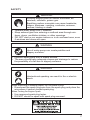
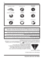
Hazard Symbols and Meanings
Save these Instructions
Safety Rules
This is the safety alert symbol. It is
used to alert you to potential personal
injury hazards. Obey all safety
messages that follow this symbol to
avoid possible injury or death.
explosion
kickback
moving parts read manual
hot surface
slippery
fire electric shock
toxic fumes
SAFETY

7
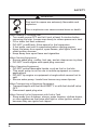
WARNING
Running engine gives o carbon monoxide, an
odorless, colorless, poison gas.
Breathing carbon monoxide can cause headache,
fatigue, dizziness, vomiting, confusion, seizures,
nausea, fainting or death.
• Operate water pump ONLY outdoors.
• Keep exhaust gas from entering a conned area through win-
dows, doors, ventilation intakes, or other openings.
• DO NOT start or run engine indoors or in an enclosed area, even
if windows and doors are open.
WARNING
Use of water pump can create puddles and
slippery surfaces.
• Operate water pump from a stable surface.
• The area should have adequate slopes and drainage to reduce
the possibility of a fall due to slippery surfaces.
WARNING
Unintentional sparking can result in re or electric
shock.
When Adjusting or Making Repairs to Your Water Pump
• Disconnect the spark plug wire from the spark plug and place the
wire where it cannot contact spark plug.
When Testing for Engine Spark
• Use approved spark plug tester.
• DO NOT check for spark with spark plug removed.
SAFETY

8
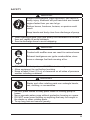
WARNING
Fuel and its vapors are extremely ammable and
explosive.
Fire or explosion can cause severe burns or death.
When Adding or Draining Fuel
• Turn water pump OFF and let it cool at least 2 minutes before
removing fuel cap. Loosen cap slowly to relieve pressure in tank.
• Fill or drain fuel tank outdoors.
• DO NOT overll tank. Allow space for fuel expansion.
• If fuel spills, wait until it evaporates before starting engine.
• Keep fuel away from sparks, open ames, pilot lights, heat, and
other ignition sources.
• Keep away from open ame and cigarettes.
When Starting Equipment
• Ensure spark plug, muer, fuel cap, and air cleaner are in place.
• DO NOT crank engine with spark plug removed.
When Operating Equipment
• DO NOT pump ammable liquids, such as fuel or fuel oils.
• This water pump is not for use in mobile equipment or marine
applications.
• DO NOT tip engine or equipment at angle which causes fuel to
spill.
• Secure water pump. Loads from hoses may cause tipover.
When Transporting or Repairing Equipment
• Transport/repair with fuel tank EMPTY or with fuel shuto valve
OFF.
• Disconnect spark plug wire.
When Storing Fuel or Equipment with Fuel in Tank
• Store away from furnaces, stoves, water heaters, clothes dryers,
or other appliances that have pilot light or other ignition source
because they can ignite fuel vapors.
SAFETY

9
WARNING
Starter cord kickback (rapid retraction) can result in
bodily injury. Kickback will pull hand and arm toward
engine faster than you can let go.
Broken bones, fractures, bruises, or sprains could
result.
Keep hands and body clear from discharge of pump.
• When starting engine, pull cord slowly until resistance is felt and
then pull rapidly to avoid kickback.
• Secure discharge hose to avoid whipping.
WARNING
Contact with muer area can result in serious burns.
Exhaust heat/gases can ignite combustibles, struc-
tures or damage fuel tank causing a re.
• DO NOT touch hot parts and AVOID hot exhaust gases.
• Allow equipment to cool before touching.
• Keep at least 5 feet (1.5 m) of clearance on all sides of pressure
washer including overhead.
WARNING
Starter and other rotating parts can entangle hands,
hair, clothing, or accessories.
• NEVER place hands or body parts inside of running pump or
hoses.
• Never operate water pump without protective housing or covers.
• DO NOT wear loose clothing or anything that may be caught in
the starter or other rotating parts.
• Tie up long hair and remove jewelry.
SAFETY

10
CAUTION
Excessively high operating speeds increase risk of injury and dam-
age to water pump.
Excessively low speeds impose a heavy load.
• DO NOT tamper with the governed speed.
• DO NOT modify the water pump.
• DO NOT allow unqualied persons or children to operate or ser-
vice water pump.
NOTICE
Improper treatment of water pump can damage it and shorten its life.
• If you have questions about intended use, ask dealer or contact
nearest authorized dealer.
• Be sure pump chamber is lled with water before starting the engine.
• Never run pump without priming.
• Use a non-collapseable hose on the suction side of the hose.
• Use water pump only for intended uses. Do not attempt to transfer
chemicals or trash in a pump that is not intented for this purpose.
• Pumping sea water, beverages, acids, chemical solutions, or any
other liquid that promotes corrosion can damage the pump.
• Ensure all connections are air tight.
• DO NOT obstruct the suction or discharge hose in any way,
obstruction of hoses can damage pump housing.
• NEVER operate pump without strainer basket connected to end of
suction hose.
• NEVER allow vehicles to drive over hoses. If a hose must be
positioned across a roadway, use planking on each side of hose to
allow vehicles to pass over without obstructing or collapsing hose.
• Anchor pump to avoid equipment movement.
• Keep equipment away from edge of river or lake where it could
cause the bank to collapse.
• DO NOT insert any objects through cooling slots.
• NEVER operate units with broken or missing parts, or without
protective housing or covers.
• DO NOT by-pass any safety device on this machine.
• NEVER move machine by pulling on hoses. Use frame on unit.
• Check fuel system for leaks or signs of deterioration, such as chafed
or spongy hose, loose or missing clamps, or damaged tank or cap.
Correct all defects before operating water pump.
SAFETY

11
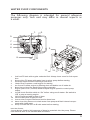
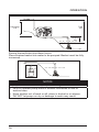
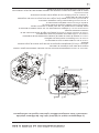
The following diagram is intended for general reference
purposes only. Your unit may dier in several aspects as
a result.
1. Fuel Tank Fill tank with regular unleaded fuel. Always leave room for fuel expan-
sion.
2. Priming Plug Fill pump with water here to prime pump before starting.
3. Discharge Outlet Connect discharge hose here.
4. Choke Lever Prepares a cold engine for starting.
5. Air Cleaner Protects engine by ltering dust and debris out of intake air.
6. Recoil Starter Used for starting the engine manually.
7. Engine Speed Lever (Throttle) Used to adjust engine speed to control pump
output.
8. On/O Switch Set this switch to “On” before using recoil starter. Set switch to
“O” to stop a running engine.
9. Oil Fill Check and add engine oil here.
10. Oil Drain Bolt Drain engine oil here.
11. Suction Inlet Connect reinforced suction hose here.
12. Water Drain Plug Remove to drain water from pump and ush internal compo-
nents with clean water.
13. Pump Chamber Be sure to ll with water before starting.
Item Not Shown:
Strainer Basket Used to limit passage of abrasive materials into the pump. Please
note that this item is not included with all models.
1.
4.
6.
8. 9.10.
11. 12. 13.
7.
5.
2.
3.
WATER PUMP COMPONENTS

12
9
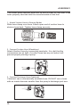
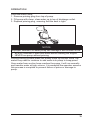
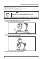
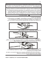
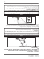
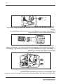
3. Slide hose clamp (A) over end of hose (B). Slide
suction hose onto hose barb (C). Tighten hose clamp
securely using a standard 1/4” (6mm) screwdriver.
Attach Suction Hose to Strainer Basket
Slide hose clamp over hose. Attach open end of suction hose
to strainer hose barb. Tighten hose clamp securely using a
standard 1/4” (6mm) screwdriver.
Connect Discharge Hose (Optional)
If desired, use a commercially available hose. DO NOT use a
hose with an inside diameter smaller than the pump’s
discharge port size.
1. Slide barb cuff over hose barb. Insert rubber seal into
end of barb cuff as shown earler.
2. Screw hose barb assembly onto pump in clockwise
rotation until hose barb assembly is tightened securely.
3. Slide hose clamp over end of discharge hose. Slide
discharge hose onto hose barb. Tighten hose clamp
securely using a standard 1/4” (6mm) screwdriver.
C
A
B
Your water pump requires some set up and is ready for use after it has
been properly serviced with the recommended oil and fuel.
1. Attach Suction Hose to Strainer Basket
Slide hose clamp over hose. Attach open end of suction hose to
strainer hose barb. Tighten hose clamp securely.
3. Connect Discharge Hose (Optional)
If desired, use a commercially available hose. DO NOT use a hose
with an inside diameter smaller than the pump’s discharge port size.
ASSEMBLY
2. Connect Suction Hose (Mandatory)
Attach Suction Hose by connecting camlocks. It is vital that the
connections are air tight. If suction hose has any air leaks it will
prevent proper priming of pump.

13
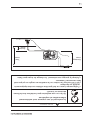
Pump Operation and set up
When setting up your pump, it is important to understand it’s lift
capacity. Lift capacity is categorized into three dierent sections.
(as shown on page 14)
Suction lift is the vertical distance from the liquid source to the pump
inlet. Due to the weight of water this can be no more than 26ft. As
such, the standard suction hose is 25ft in length. The shorter the
suction lift distance, the faster the machine will prime and the better it’s
performance. Discharge lift is the vertical distance between the pump’s
discharge port to the end of the discharge hose. This distance will vary
depending on the size, and power of the machine.
Total lift is the sum of the suction lift, and the discharge lift. This is
the total vertical lift capacity of the machine from water source to
discharge point. As total lift increases, the output ow rate of the water
decreases.
Keep in mind, “Lift” denes the vertical lifting capacity. If the liquid is
being moved horizontally, then the pump can move it a much greater
distance (in this event, always add hose length to the discharge side,
never the suction side.)
*Please note, in some instances the word “head” can be used to refer
to “lift”.
Move Water Pump to Safe Operating Location
For best pump performance, locate the pump on a at, level surface
as close as possible to the water to be pumped. Secure water pump to
avoid tip-over. Use hoses that are no longer than necessary.
IMPORTANT: Direct open end of discharge hose away from home,
electrical devices or anything not desired to get wet.
WARNING
Fuel and its vapors are extremely ammable and
explosive.
Fire or explosion can cause severe burns or death.
• This water pump is not for use in mobile equipment or marine
applications
• DO NOT tip engine or equipment at angle which causes fuel to spill.
• Secure water pump. Loads from hoses may cause tip over.
OPERATION

14
Discharge
Lift
Total
Lift
Suction
Lift
OPERATION
Placing Strainer Basket Into Water Source
Place strainer basket into water to be pumped. Basket must be fully
immersed.
NOTICE
Improper treatment of water pump can damage it and shorten its life.
• NEVER operate pump without strainer connected to end of
suction hose.
• Keep strainer out of sand or silt, place in bucket or on stones.
• DO NOT let pump run dry or damage to seals may result.

15
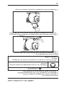
Prime the Water Pump
1. Remove priming plug from top of pump.
2. Fill pump with clean, clear water up to top of discharge outlet.
3. Replace priming plug, ensuring that the seal is tight.
During priming process water will slowly move up suction hose. Op-
erator may need to continue to add water into pump to keep prime.
Once water from suction hose reaches the pump, it will run normally
and transfer water at high volume. It is essential the operator ensures
this process is complete to prevent failure of prime or damage to
pump.
NOTICE
Improper treatment of water pump can damage it and shorten its life.
• Be sure chamber is lled with water before starting the engine.
• NEVER run pump without priming
OPERATION

16
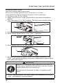
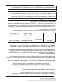
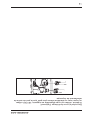
Starting the Water Pump
Use the following start instructions:
Must ensure pump is primed, and suction hose is in water
source before turning on engine. (see page 14 for instructions)
1. Fill Engine with Oil, SAE 10W30
2. Make sure unit is on a at, level surface and pump chamber is
primed.
3. Turn fuel valve (1) to “On” position. The fuel valve handle will be
vertical (pointing toward the ground).
4. Push on/o switch (2) to “On” position.
5. Move engine speed lever (3) to “Fast” ( ) position.
7. Grasp recoil handle and pull slowly until slight resistance is felt.
Then pull handle rapidly to overcome compression, prevent kick-
back and start engine.
6. Move choke lever (4) to “On” position.
2
3
4
1
WARNING
Starter cord kickback (rapid retraction) can result in
bodily injury. Kickback will pull hand and arm toward
engine faster than you can let go.
Broken bones, fractures, bruises, or sprains could
result.
• When starting engine, pull cord slowly until resistance is felt and
then pull rapidly to avoid kickback.
STARTING THE WATER PUMP

ATTENTION
*Always check the engine oil level and quality before starting. If
the engine oil is too low or of poor quality, the engine may not be
properly lubricated and suer damage. Engines equipped with an
automatic low oil shutdown will not start if the oil level is too low.
**NOTE: Model WP-2065HL will require more frequent oil checks to
ensure oil quality if unit operates under low power conditions.
17
IMPORTANT: If excessive fuel is present in the air/fuel mixture caus-
ing a “ooded” condition, move choke lever to “Run” position and pull
handle repeatedly until engine starts.
8. Move choke lever to “Run” position a short distance at a time over
several seconds in warm weather or minutes in cold weather. Let
engine run smoothly before each change. Operate with choke in
“Run” position.
IMPORTANT: It may take a few minutes for water pump to begin
pumping water.
WARNING
Contact with muer area can result in serious burns.
Exhaust heat/gases can ignite combustibles, struc-
tures or damage fuel tank causing a re.
• DO NOT touch hot parts and AVOID hot exhaust gases.
• Allow equipment to cool before touching.
• Keep at least 5 feet (1.5 m) of clearance on all sides of pressure
washer including overhead.
It is recommended to have the engine on full RPM during operation.
STARTING THE WATER PUMP

18
WARNING
Backre, re or engine damage could occur.
• DO NOT stop engine by moving choke control to “Choke” position.
Stopping the Water Pump
1. Move engine speed lever to “Slow” position.
2. Push on/o switch to “O” position.
3. Turn fuel valve to “O” position.
Drain and Flush Water Pump
1. Disconnect and drain suction and discharge hoses.
2. Remove drain plug at bottom of pump.
3. Remove primer plug from top of pump and ush internal compo-
nents of pump with clean water.
4. Replace both plugs and nger tighten.
STOPPING THE WATER PUMP

19
HIGH ALTITUDE REPLACEMENT KIT
WARNING
To prevent serious injury from re: Follow the kit procedures in
a well-ventilated area away from ignition sources. If the engine
is hot from use, shut the engine o and wait for it to cool before
proceeding.
NOTICE
The warranty may be void if necessary adjustments are not made
for high altitude use.
HIGH ALTITUDE REPLACEMENT KIT FOR EPAIII ENGINES
3000ft to 6000ft or 6000ft to 8000ft of elevation
• At high altitude, the standard carburetor air-fuel mixture will be too
rich. Performance will decrease and fuel consumption will increase. A
very rich mixture will also foul the spark plug and cause hard starting.
Operation at an altitude that diers from that at which this engine was
certied, for extended periods of time, may increase emissions.
• The fuel system on this Engine or Equipment may be inuenced
by operation at higher altitudes. Proper operation can be ensured
by installing an altitude kit when required. See the table below to
determine when an altitude kit is required. Operating this generator
without the proper altitude kit installed may increase the engine’s
emissions and decrease fuel economy and performance. Kits may
be obtained from any Dealer, and should be installed by a qualied
individual.
• Engine, Generator Set, Pressure Washer, Walk-Behind Lawnmower,
Compressor, Pump, Tiller etc.
** Elevation above sea level.
• This high altitude jet is to be used at elevations above 3000 feet.
• At elevations above 8000 feet, the engine may experience
decreased performance, even with the high altitude kit.
If a carburetor is replaced, the proper high altitude kit jet will need to be
installed into the replacement carburetor.
Equipment model* Fuel Altitude
Range** Kit Part Num-
ber
Gasoline
0 – 3000 ft Not Required
3000 – 6000 ft Altitude kit 1#
6000 – 8000 ft Altitude kit 2#

20
CARB AND EPA WARRANTY
CALIFORNIA AND FEDERAL EXHAUST AND EVAPORATIVE
EMISSIONS CONTROL WARRANTY STATEMENT
YOUR WARRANTY RIGHTS AND OBLIGATIONS
The California Air Resources Board, the United States Environmental Protection Agency
and Chongqing Rato Technology Co., Ltd. (Rato), are pleased to xplain the exhaust
and evaporative emissions (“emissions”) control system warranty on your 2019/2020
small o-road engine/equipment.
In California, new equipment that use small o-road engines must be designed, built,
and equipped to meet the State’s stringent anti-smog standards. Rato must warrant the
emissions control system on your small o-road engine/equipment for the period listed
below provided there has been no abuse, neglect or improper maintenance of your
small o-road engine/equipment leading to the failure of the emissions control system.
Your emissions control system may include parts such as the carburetor or fuel-injection
system, the ignition system, catalytic converter, fuel tanks, fuel lines (for liquid fuel
and fuel vapors), fuel caps, valves, canisters, lters, clamps and other associated
components. Also included may be hoses, belts, connectors, and other emission-related
assemblies.
Where a warrantable condition exists, Rato will repair your small o-road engine/
equipment at no cost to you including diagnosis, parts and labor.
MANUFACTURER’S WARRANTY COVERAGE
The exhaust and evaporative emissions control system on your small o-road engine/
equipment is warranted for two years. If any emissions-related part on your small o-
road engine/equipment is defective, the part will be repaired or replaced by Rato.
OWNER’S WARRANTY RESPONSIBILITIES
As the small o-road engine/equipment owner, you are responsible for performance of
the required maintenance listed in your owner’s manual. Rato recommends that you
retain all receipts covering maintenance on your small o-road engine/equipment, but
Rato cannot deny warranty coveage solely for the lack of receipts or for your failure to
ensure the performance of all scheduled maintenance.
As the small o-road engine/equipment owner, you should however be aware that Rato
may deny your warranty coverage if your small o-road engine/equipment or a part has
failed due to abuse, neglect, or improper maintenance or unapproved modications.
You are responsible for presenting your small o-road engine/equipment to a Rato
distribution center or service center as soon as the problem exists. The warranty repairs
La page est en cours de chargement...
La page est en cours de chargement...
La page est en cours de chargement...
La page est en cours de chargement...
La page est en cours de chargement...
La page est en cours de chargement...
La page est en cours de chargement...
La page est en cours de chargement...
La page est en cours de chargement...
La page est en cours de chargement...
La page est en cours de chargement...
La page est en cours de chargement...
La page est en cours de chargement...
La page est en cours de chargement...
La page est en cours de chargement...
La page est en cours de chargement...
La page est en cours de chargement...
La page est en cours de chargement...
La page est en cours de chargement...
La page est en cours de chargement...
La page est en cours de chargement...
La page est en cours de chargement...
La page est en cours de chargement...
La page est en cours de chargement...
La page est en cours de chargement...
La page est en cours de chargement...
La page est en cours de chargement...
La page est en cours de chargement...
-
 1
1
-
 2
2
-
 3
3
-
 4
4
-
 5
5
-
 6
6
-
 7
7
-
 8
8
-
 9
9
-
 10
10
-
 11
11
-
 12
12
-
 13
13
-
 14
14
-
 15
15
-
 16
16
-
 17
17
-
 18
18
-
 19
19
-
 20
20
-
 21
21
-
 22
22
-
 23
23
-
 24
24
-
 25
25
-
 26
26
-
 27
27
-
 28
28
-
 29
29
-
 30
30
-
 31
31
-
 32
32
-
 33
33
-
 34
34
-
 35
35
-
 36
36
-
 37
37
-
 38
38
-
 39
39
-
 40
40
-
 41
41
-
 42
42
-
 43
43
-
 44
44
-
 45
45
-
 46
46
-
 47
47
-
 48
48


Powerfist 8509960 Le manuel du propriétaire
- Taper
- Le manuel du propriétaire
dans d''autres langues
- English: Powerfist 8509960 Owner's manual
Autres documents
-
Homelite ut40520 Le manuel du propriétaire
-
-
 BE Pressure Supply 8518250 Le manuel du propriétaire
-
Briggs & Stratton 73019 Manuel utilisateur
-
Briggs & Stratton 073021 Manuel utilisateur
-
-
-
-
-
Honda 9202011 Le manuel du propriétaire
