PROPOINT 9066697 Le manuel du propriétaire
- Catégorie
- Coupe-bordures
- Taper
- Le manuel du propriétaire

V1.0 9066697
Please read and understand all instructions before use. Retain this manual for future reference.

9066697 Industrial Ceiling Fan V1.0
2 For technical questions call 1-800-665-8685
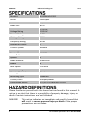
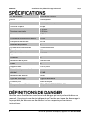
Model #
6HEP84APLK235C
Series
Helicopter
Airflow
13,452 CFM
Blade Size
84 in.
Voltage Rating
170V DC
120V AC
Current Rating
0.72A
Wattage Rating
18W
Frequency Rating
60 Hz
Number of Phases
1
Control System
Remote
Motor Type
DC
Bearing Type
6202ZZ
Speeds
5
Blade Material
Aluminum
Blades
6
Max. Speed
100 RPM
Decibel Rating
41 dB
Housing Material
Steel
Mounting Type
Downrod
Colour/Finish
Antique pewter
Certification Marks
ETL/cETL 210800385TCH-001
Please familiarize yourself with the hazard notices found in this manual. A
notice is an alert that there is a possibility of property damage, injury or
death if certain instructions are not followed.
DANGER! This notice indicates an immediate and specific hazard that
will result in severe personal injury or death if the proper
precautions are not taken.

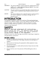
V1.0 Industrial Ceiling Fan 9066697
Visit www.princessauto.com for more information 3
WARNING! This notice indicates a specific hazard or unsafe practice that
could result in severe personal injury or death if the proper
precautions are not taken.
CAUTION! This notice indicates a potentially hazardous situation that may
result in minor or moderate injury if proper practices are not
taken.
NOTICE! This notice indicates that a specific hazard or unsafe practice
will result in equipment or property damage, but not
personal injury.
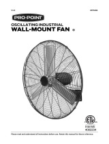
This powerful ceiling fan is ideal for increasing airflow and cooling large
commercial or industrial spaces. It has a max. speed of 100 RPM, and its 6
aluminum blades output 13,452 CFM of airflow. It features 5 unique
speeds, including reversing capabilities, and comes with a convenient
remote for easy operation.
WARNING! Read and understand all instructions
before using this tool. The operator must follow
basic precautions to reduce the risk of personal
injury and/or damage to the equipment.
Keep this manual for safety warnings, precautions, operating or inspection
and maintenance instructions.
1. Operate in a safe work environment. Keep your work area clean, well-
lit and free of distractions. Place lights so you are not working in a
shadow.
2. Keep anyone not wearing the appropriate safety equipment away
from the work area.
3. Store tools properly in a safe and dry location. Keep tools out of the
reach of children.
4. Do not install or use in the presence of flammable gases, dust or
liquids.

9066697 Industrial Ceiling Fan V1.0
4 For technical questions call 1-800-665-8685
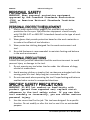
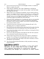
WARNING! Wear personal protective equipment
approved by the Canadian Standards Association
(CSA) or American National Standards Institute
(ANSI).
1. Always wear impact safety goggles that provide front and side
protection for the eyes. Eye protection equipment should comply
with CSA Z94.3-07 or ANSI Z87.1 standards based on the type of work
performed.
2. Wear gloves that provide protection based on the work materials or
to reduce the effects of tool vibration.
3. Wear protective clothing designed for the work environment and
tool.
4. Non-skid footwear is recommended to maintain footing and balance
in the work environment.
Control the tool, personal movement and the work environment to avoid
personal injury or damage to the tool.
1. Do not operate any tool when tired or under the influence of drugs,
alcohol or medications.
2. Avoid wearing clothes or jewelry that can become entangled with the
moving parts of a tool. Keep long hair covered or bound.
3. Do not overreach when operating the tool. Proper footing and balance
enables better control in unexpected situations.
WARNING! DO NOT let comfort or familiarity with
product (gained from repeated use) replace strict
adherence to the tool safety rules. If you use this
tool unsafely or incorrectly, you can suffer serious
personal injury.
1. Use the correct tool for the job. This tool was designed for a specific
function. Do not modify or alter this tool or use it for an unintended
purpose.

V1.0 Industrial Ceiling Fan 9066697
Visit www.princessauto.com for more information 5
2. Do not use the tool if any parts are damaged, broken or misplaced.
Repair or replace the parts.
3. Ensure that the installation site is clear of obstructions and that the
rotating blades do not come in contact with any object. Install the blades
10 ft away from the floor.
4. Mount the fan on a ceiling joist if possible; the joist must be able to
support the weight of the moving fan. If mounting on a ceiling outlet
box, use a 4 x 2-1/8 in. deep, metal octagon box that is UL-listed as
suitable for fan use and capable of supporting 35 lb or less. Use the
mounting hardware provided with the outlet box.
5. Only use UL/ETL listed light kits if installing kits that are not provided
with the fan. Refer to the kit's manual for installation procedures.
Disconnect the fan from the supply circuit before installing the light
kit to prevent electric shock.
6. Protect the fan motor housing's finish by keeping the part in the
packaging until it is ready for installation.
7. Do not attach the fan blades before mounting the fan motor housing.
If installing more than one ceiling fan, do not mix the blade sets.
8. Do not bend the blade brackets while installing or cleaning the fan to
prevent personal injury.
9. Do not use solid-state speed control devices with the fan to prevent
fire or electrical hazards and personal injury.
10. Ensure that all connections are secure once the fan is mounted to
prevent it from falling and causing damage and/or personal injury.
11. The fan is pre-lubricated and ready for use after installation. Further
lubrication is not necessary.
12. Turn the fan off and allow the blades to fully stop before reversing
the fan direction.
WARNING! Do not touch or handle a live tool with
any part of your body that is wet or damp. Wet
skin reduces resistance to electrical current,
increasing the danger of a serious or fatal shock.

9066697 Industrial Ceiling Fan V1.0
6 For technical questions call 1-800-665-8685
1. Protect yourself against electric shocks when working on electrical
equipment. Avoid body contact with grounded surfaces. There is an
increased chance of electrical shock if your body is grounded.
2. Do not expose the tool to rain or wet conditions. Water entering a
power tool will increase the risk of electric shock.
3. Do not alter any parts of the tool or accessories. All parts and
accessories are designed with built-in safety features that may be
compromised if altered.
4. Make certain the power source conforms to requirements of your
equipment (see Specifications).
5. When wiring an electrically driven device, follow all electrical and
safety codes, as well as the most recent Canadian Electrical Code (CE)
and Canadian Centre for Occupational Health and Safety (CCOHS).
WARNING! All wiring should be performed by a
qualified electrician.
WARNING! Do not operate the tool if any part is
missing. Replace the missing part before
operating. Failure to do so could result in a
malfunction and personal injury.
Remove the parts and accessories from the packaging and inspect for damage.
Make sure that all items in the parts list are included.
Numbered references in parenthesis (#1) refer to the included Parts List.
Dashed numbers in parenthesis (Fig. 1-1) refer to a specific point in an
illustration or image.
WARNING! Switch off the appropriate circuit
breakers at the electrical panel before starting
to avoid electrical shock.
WARNING! Use an outlet box that can support up to
35 lb to prevent the fan from falling and causing
damage and/or personal injury.

V1.0 Industrial Ceiling Fan 9066697
Visit www.princessauto.com for more information 7
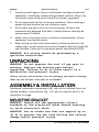
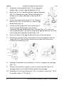
1. Install the mounting bracket (#1) to the outlet box in
the ceiling (Fig.1-1) by using screws (not included) and
the appropriate supplied washers.
2. Remove the cross pin (Fig. 2-1) and cotter pin (Fig. 2-
2) from the downrod (#2).
3. Loosen the 2 downrod jam screws (Fig. 3-1). Ensure
that the position of the hex nut is on the same side as
the set screw head.
4. Insert the yoke cover (#5), deco ring (#4) and canopy
(#3) onto the downrod (Fig. 4).
5. Feed the motor lead wires (Fig. 5-1) through the
downrod and then insert the downrod assembly
into the yoke (Fig. 5-2). Insert the cross pin
(Fig. 5-3) through the yoke and downrod and
secure with the cotter pin Fig. 5-4).
6. Tighten both the downrod screws to secure
in place.
7. Use a wrench to tighten the hex nut securely against the yoke
(Fig. 6-1) then pull down the yoke cover to cover the yoke (Fig. 6-2).
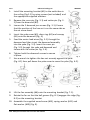
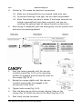
8. Lift the fan assembly (#6) onto the mounting bracket (Fig. 7-1).
9. Rotate the fan so that the ball groove (Fig. 8-1) engages the ridge (Fig.
8-2) on the mounting bracket.
10. Assemble the supplied wood screw (#13), spring washer (#11) and
flat washer (#10) (Fig. 9).
Fig. 1
Fig. 2
Fig. 3
Fig. 4
Fig. 5
Fig. 6

9066697 Industrial Ceiling Fan V1.0
8 For technical questions call 1-800-665-8685
11. Pass the wood screw through the closed loop of the safety cable (Fig.
9-1).
12. Secure the wood screw to ceiling joist through any available slot on
the mounting bracket (Fig. 9-2).
13. Make sure safety cable has been tightened securely.
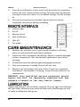
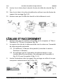
1. Ensure that model number on receiver (#26) and the transmitter
(#25) are the same (Fig. 10).
2. The remote serial number will be the same on the pre-paired remote
set.
2.1 If they are different, they will need to be paired (see Transmitter
section below).
2.2 Do not mix the remote sets if you are installing more than one
fan. Do not mix the A Set (Fig. 11-1) with the B Set (Fig. 11-2).
3. Insert the receiver into the mounting bracket, being careful not to
squeeze the wires excessively (Fig. 12).
Fig. 7
Fig. 8
Fig. 9
Fig. 10
Fig. 11
Fig. 12

V1.0 Industrial Ceiling Fan 9066697
Visit www.princessauto.com for more information 9
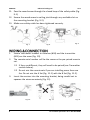
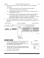
4. Follow Fig. 13 to make the electrical connections.
4.1 Make sure all exposed wires are secured inside wire nuts.
4.2 To prevent flickering in the light, the unit must be grounded.
4.3 Wires from house may vary in colour. If the house wires do not
include a ground/Earth wire (bare or green), and you are
installing the optional light kit, please consult an electrician.
5. After wiring is completed, push the wires gently into the junction box
with wire nuts pointing upward.
1. Push the canopy upwards until the two pre-
installed screws (Fig. 14-1) on the mounting
bracket are engaged with the two key holes on
the canopy (Fig. 14-2).
2. Rotate the canopy slightly until the two pre-
installed screw heads are engaged in the
narrow end of the holes.
3. Tighten both screws (Fig. 14-3).
4. Push the deco ring up to the canopy, aligning holes on the
canopy (Fig. 15-1) with the nibs on the deco ring (Fig. 15-2).
5. Push firmly to snap into place.
Fig. 14
Fig. 15
Fig. 13

9066697 Industrial Ceiling Fan V1.0
10 For technical questions call 1-800-665-8685
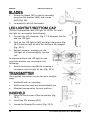
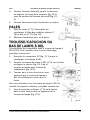
1. Attach the blades (#7) to the fan assembly
using the flat washers (#14) and screws
(#15) (Fig. 16).
2. Complete for all 6 of the blades.
This fan is compatible with LED light kit LK235. To install
this light kit, accomplish the following:
1. Connect the JST connector (Fig. 17-1) between the fan
and the LED light.
2. Push up the LED light kit (#9) and align the groove (Fig.
18-1) from the light kit with the slot from the adapter
(Fig. 18-2).
3. Rotate clockwise, making sure the
LED light kit is twisted tightly into the
slot.
To operate without the LED light kit and
install the bottom cap, accomplish the
following:
1. Attach the bottom cap (#8) by screwing it
clockwise onto the light kit pan (Fig. 19-1).
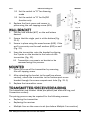
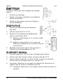
The supplied transmitter can be set up in multiple
ways:
• Handheld with no mounting
• Wall bracket for both wall and handheld use
• Mounted permanently for only wall use
1. Open the front cover of the transmitter (Fig.
20-1).
2. Install the 12V battery (#24).
3. Locate the Dimmer/On switch (Fig. 20-2).
Fig. 16
Fig. 17
Fig. 18
Fig. 19
Fig. 20

V1.0 Industrial Ceiling Fan 9066697
Visit www.princessauto.com for more information 11
3.1 Set the switch to “D” for dimming
mode
3.2 Set the switch to “O’ for On/Off
function only.
4. Replace the front cover and secure in
place using the self-tapping screw (#22).
1. Position the bracket (#27) on the wall where
desired.
2. Ensure that the single post is at the bottom (Fig.
21-1).
3. Secure in place using the wood screws (#19). If the
wall is concrete, use the wall anchors (#20) as well
(Fig. 21).
4. Snap the transmitter onto the bracket by aligning
the 3 posts on the bracket to the holes on the
transmitter (Fig. 22).
4.1 Transmitter can remain on bracket or be
removed using this process.
1. Open the cover of the transmitter by removing
the self-tapping screw.
2. After attaching the bracket to the wall (see above
section), attach the transmitter to the bottom post of the
bracket through the screw compartment hole (Fig. 23-1).
3. Replace the transmitter cover.
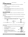
The transmitter and receiver come pre-paired (see above Wiring and
Connection section).
The pairing process may be required for the following reasons:
• Replacing the transmitter
• Replacing the receiver
• Multiple fans on the same circuit (see below Multiple Fans section)
Fig. 21
Fig. 22
Fig. 23

9066697 Industrial Ceiling Fan V1.0
12 For technical questions call 1-800-665-8685
1. Turn off the main power and make sure the fan has completely
stopped.
2. Install a new receiver or install the new transmitter.
3. Turn on the power.
4. Press and hold the on/off button for 8 seconds until the receiver
performs a long beep.
4.1 Note that this must be done within 20 seconds of the power
being turned on.
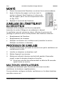
This model of fan has the ability to cooperate with additional fans and
transmitters.
If you wish to set up multiple fans on the same transmitter, accomplish the
following:
1. Install fans properly and at the same time (see above Assembly &
Installation sections).
2. Perform the pairing process (see above Pairing Process section) from
a physical point in-between the fans (Fig. 24).
If you wish to set up multiple fans with multiple transmitters, accomplish
the following:
1. Install fans properly and at the same time (see above Assembly &
Installation sections).
2. Turn off the power at the appropriate
circuit breaker.
3. Lower the canopy on fan #1 and
disconnect the black wire (Fig. 25-1).
Place wire nut on the black wire end from
the house.
Fig. 24
Fig. 25

V1.0 Industrial Ceiling Fan 9066697
Visit www.princessauto.com for more information 13
4. Turn on the power at the appropriate circuit breaker.
5. Follow the instructions in the above Pairing Process section to
successfully the pair fan #1.
6. Turn off the power at the appropriate circuit breaker.
7. Lower the canopy on fan #2 and disconnect the black wire (Fig. 25-1).
Place wire nut on the black wire end from the house.
8. Reconnect the black wire on fan #1.
9. Turn on the power at the appropriate circuit breaker.
10. Follow the instructions in the above Pairing Process section to
successfully pair fan #2.
11. Turn off the power at the appropriate circuit breaker.
12. Replace the canopies for both fans.
13. Turn on the power at the appropriate circuit breaker.
1. After installation is completed correctly, turn the appropriate circuit
breakers back on to begin using the fan.
2. Press the on/off button on the transmitter to turn the fan on. This will
be confirmed with a beeping sound and a flashing of the red indicator
light.
2.1 Upon every startup, the fan will move forward and backward for
3 seconds.
2.2 Do not press and hold the on/off button for longer than 4
seconds. Doing so will result in a factory reset, which will erase
any pre-pairing of the receiver and transmitter and
programming.
3. Use the light on/dimmer button to adjust the light.
3.1 A short press of the button turns the light on.
3.2 Holding the button will dim the light.
4. Use the fan speed button to adjust the speed.
4.1 1 is the lowest speed and 5 is the highest.

9066697 Industrial Ceiling Fan V1.0
14 For technical questions call 1-800-665-8685
5. Press the on/off button to turn the fan off. Note that the transmitter
retains the most recent previous setting. Disconnecting the fan from
the power source will return it to its default settings: fan off and light
on.
6. If fan does not operate as intended, please revisit the above
installation instructions before proceeding.
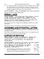
A Indicator light
B On/off
C Reverse switch
D Light on/dimmer
E Light off
F Fan speed
1. Maintain the tool with care. A tool in good condition is efficient,
easier to control and will have fewer problems.
2. Inspect the tool components periodically. Repair or replace damaged
or worn components. Only use identical replacement parts when
servicing.
3. Follow instructions for lubricating and changing accessories.
4. Only use accessories intended for use with this tool.
5. Maintain the tool’s labels and name plates. These carry important
information. If unreadable or missing, contact Princess Auto Ltd. for
replacements.
WARNING! Only qualified service personnel should
repair the tool. An improperly repaired tool may
present a hazard to the user and/or others.
Inspect and lubricate the tool when required. Only use light oil to lubricate
the tool. Other lubricants may not be suitable and could damage the tool
or cause a malfunction during use.

V1.0 Industrial Ceiling Fan 9066697
Visit www.princessauto.com for more information 15
When not in use for an extended period, apply a thin coat of lubricant to
the steel parts to avoid rust. Remove the lubricant before using the tool
again.
NOTICE! NEVER use a penetrating oil to lubricate
the tool. Penetrating oil may act as a solvent
that will break down the grease and cause the tool
to seize up.
Recycle a tool damaged beyond repair at the appropriate facility.
Contact your local municipality for a list of disposal facilities or by-laws for
electronic devices, batteries, oil or other toxic liquids.
IMPORTANT! DO NOT pollute the environment by
allowing uncontrolled discharge of waste oil.
In the event that the fan does operate properly, revisit the steps found in
the Assembly & Installation sections, particularly the Wiring & Connection
section and the Transmitter/Receiver Pairing section.
If the fan continues to malfunction, cease operation and have a qualified
technician service the tool or visit a Princess Auto Ltd. location for a
solution.

9066697 Industrial Ceiling Fan V1.0
16 For technical questions call 1-800-665-8685

V1.0 Industrial Ceiling Fan 9066697
Visit www.princessauto.com for more information 17
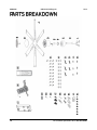
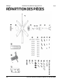
#
DESCRIPTION
QTY
1
Mounting bracket
1
2
Downrod
1
3
Canopy
1
4
Deco ring
1
5
Yoke cover
1
6
Fan assembly
1
7
Extruded aluminum blades
6
8
Bottom cap
1
9
LED light kit
1
10
Flat washer
3
11
Spring washer
3
12
Machine screw
2
13
Wood screw
3
14
Flat washer
19
15
Blade screw
19
16
Wire nut
8
17
Balanced slide
1
18
Weight block
3
19
Wood screw
2
20
Wall anchor
2
21
Wire nut
3
22
Self-tapping screw (battery cover)
1
23
Self-tapping screw (wall mount)
1
24
Battery
1
25
Handheld transmitter
1
26
Receiver
1
27
On-wall bracket
1

9066697 Industrial Ceiling Fan V1.0
18 For technical questions call 1-800-665-8685

V1.0 Industrial Ceiling Fan 9066697
Visit www.princessauto.com for more information 19

9066697 Industrial Ceiling Fan V1.0
20 For technical questions call 1-800-665-8685
La page est en cours de chargement...
La page est en cours de chargement...
La page est en cours de chargement...
La page est en cours de chargement...
La page est en cours de chargement...
La page est en cours de chargement...
La page est en cours de chargement...
La page est en cours de chargement...
La page est en cours de chargement...
La page est en cours de chargement...
La page est en cours de chargement...
La page est en cours de chargement...
La page est en cours de chargement...
La page est en cours de chargement...
La page est en cours de chargement...
La page est en cours de chargement...
La page est en cours de chargement...
La page est en cours de chargement...
La page est en cours de chargement...
La page est en cours de chargement...
-
 1
1
-
 2
2
-
 3
3
-
 4
4
-
 5
5
-
 6
6
-
 7
7
-
 8
8
-
 9
9
-
 10
10
-
 11
11
-
 12
12
-
 13
13
-
 14
14
-
 15
15
-
 16
16
-
 17
17
-
 18
18
-
 19
19
-
 20
20
-
 21
21
-
 22
22
-
 23
23
-
 24
24
-
 25
25
-
 26
26
-
 27
27
-
 28
28
-
 29
29
-
 30
30
-
 31
31
-
 32
32
-
 33
33
-
 34
34
-
 35
35
-
 36
36
-
 37
37
-
 38
38
-
 39
39
-
 40
40


PROPOINT 9066697 Le manuel du propriétaire
- Catégorie
- Coupe-bordures
- Taper
- Le manuel du propriétaire
dans d''autres langues
- English: PROPOINT 9066697 Owner's manual
Documents connexes
Autres documents
-
Powerfist 9105131 Le manuel du propriétaire
-
-
 PRO POINT 8975286 Manuel utilisateur
-
-
-
-
-
-
-
Power Fist 8474975 Le manuel du propriétaire
