United States Stove VG5722-W Le manuel du propriétaire
- Catégorie
- Poêles
- Taper
- Le manuel du propriétaire

* All Pictures In This Manual Are For Illustrative Purposes Only. Actual Product May Vary.
© 2023 United States Stove Company, 227 Industrial Park Rd., South Pittsburg, TN 37380 Ph. 800-750-2723
THIS MANUAL IS SUBJECT TO CHANGE WITHOUT NOTICE.
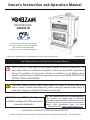
Owner’s Instruction and Operation Manual
U.S. Environmental Protection Agency
Certied to comply with 2020 particulate
emissions standards.
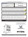
SAFETY NOTICE: If this heater is not properly installed, a house re may result. For
your safety, follow the installation instructions. Never use make-shift compromises
during the installation of this heater. Contact local building or re ocials about
permits, restrictions and installation requirements in your area. NEVER OPERATE THIS
PRODUCT WHILE UNATTENDED.
CAUTION! Please read this entire manual before you install or use your new room
heater. Failure to follow instructions may result in property damage, bodily injury, or
even death. Improper Installation Will Void Your Warranty!
Save These Instructions In A Safe Place For Future Reference.
CALIFORNIA PROPOSITION 65 WARNING:
This product can expose you to chemicals
including carbon monoxide, which is known to the
State of California to cause cancer, birth defects,
and/or other reproductive harm. For more
information, go to www.P65warnings.ca.gov
854003B-4206M
VG5722-W
R
Report #: F22-782
Certied to ASTM E1509-2022 and CAN/ULC
S627:2023; Complies to CAN ICES-3(B)/NMB-
3(B); Contains IC:23243-WBR1DIPEX
Mobile Home / Transportable Building Approved
Model Number:

2
© 2023 United States Stove Company
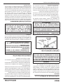
Your pellet stove has been safety tested and listed to ASTM E1509-2022 and CAN/ULC S627:2023. This manual describes
the installation and operation of the Vogelzang VG5722-W pellet stove. This heater meets the 2020 U.S. Environmental
Protection Agency’s emission limits for wood-heaters sold after May 15, 2020. Under specic EPA test conditions burning
wood pellet fuel this heater has been shown to deliver heat at a rate of 13,640 to 32,591 Btu/hr. This heater achieved a
particulate emissions rate of 1.5 g/hr when tested to method ASTM E 2779 / EPA Method 28R and 76% eciency.
INTRODUCTION
Heating Specications
Fuel Burn Rate* 2.1 to 5 lbs/hr (0.97 to
2.26 kg/hr) * Pellet size may effect the actual rate of fuel feed
and burn times. Fuel feed rates may vary by as much
as 20%. Use PFI listed fuel for best results.
Burn Time (lowest setting) 80 hrs.
Hopper Capacity 170lbs. (77kg)
Flue Size 3” or 4”
Electrical Specications
Electrical Rating 110-120 Volts AC, 60 HZ, 3.0 Amps
Watts (operational) 162 (approx.)
Watts (igniter running) 332 (approx.)
Dimensions
Overall: Height x Width X Depth 40” (1003mm) X 26” (660mm) X 30” (762mm)
WARNING:
IT IS AGAINST FEDERAL REGULATIONS TO OPERATE THIS WOOD HEATER IN A MANNER INCONSISTENT WITH THE
OPERATING INSTRUCTIONS IN THE OWNER’S MANUAL.
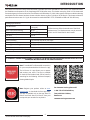
For Customer Service, please call:
1-800-750-2723 Ext 5050 or;
Text to 423-301-5624 or;
Email us at:
customerservice@usstove.com
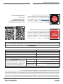
Note: Register your product online at www.
usstove.com or download the free app today.
This app is available only on the App Store for
iPhone and iPad. Search US Stove. Save your
receipt with your records for any claims.
Note: To enable WiFi or Bluetooth® connectivity
for your stove, download the US Stove Co. App.
The US Stove Co. app allows you to operate
and monitor your stove. The App is available
for both iOS and Android and can be found by
searching for the following: US Stove Company
Heating Made Simple.

© 2023 United States Stove Company
3
INSTALLATION CHECKLIST
Your Wood Stove should be installed by a qualied installer only. An NFI qualied Installer can be found at www.ncertied.
org/public/nd-an-n-pro/
CUSTOMER SERVICE
1-800-750-2723 ext 5050
Text to 423-301-5624
Email to: Customerservice@usstove.com
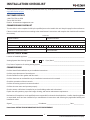
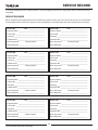
COMMISSIONING CHECKLIST
This checklist is to be completed in full by the qualied person who installs this unit. Keep this page for future reference.
Failure to install and commission according to the manufacturer’s instructions and complete this checklist will invalidate
the warranty.
Please Print
Customer Name: Telephone Number:
Address:
Model:
Serial Number:
Installation Company Name: Phone Number:
Installation Technician’s Name: License Number:
DESCRIPTION OF WORK
Location of installed appliance: _____________________________________________________________________________________
Venting System: New Venting System Yes No If yes, Brand ______________________________________________
If no, Date of inspection of existing venting system: __________________________________________________________________
COMMISSIONING
Conrm Hearth Pad Installation as per Installation Instructions .........................................................................................
Conrm proper placement of internal parts ...........................................................................................................................
Check soundness of door gasket and door seals .................................................................................................................
Conrm clearances to combustibles as per installation instructions in this manual .........................................................
Check the operations of the air controls ................................................................................................................................
Conrm the venting system is secure and sealed .................................................................................................................
Conrm the stove starts and operates properly ....................................................................................................................
Check to ensure a CO alarm is installed as per local building codes and is functional ......................................................
Explain the safe operation, proper fuel usage, cleaning, and routine maintenance requirements .....................................
Declaration of Completion: As the qualied person responsible for the work described above, I conrm that the appliance
as associated work has been installed as per manufacturer’s instructions and following any applicable building and
installation codes.
Signed: _______________________________________ Print Name: ___________________________________ Date: _______________
Home Owner: RETAIN THIS INFORMATION FOR FUTURE REFERENCE

4
© 2023 United States Stove Company
INSTALLATION
FOR CUSTOMER SERVICE CALL: 800-750-2723 EXT 5050
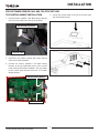
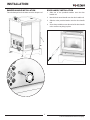
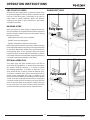
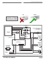
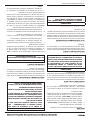
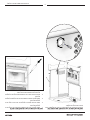
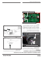
TOP CONTROL MOUNT INSTALLATION
1. Pull the factory installed 5 Pin Main Wiring Harness
and 7 Pin Com Cabel out of the top of the stove.
5 Pin Main Wiring Harness
7 Pin Com Cable
2. Unpack the top mount controls and ensure that all
wires are securely attached.
3. Connect the factory installed 5 Pin Main Wiring
Harness to the top right-hand corner of the control
panel. Connect the factory installed 7 Pin Com Cabel
to the control panel directly below the 5 Pin Main
Wiring Harness.
7 Pin Com Cable
5 Pin Main Wiring Harness
4. Secure the control panel to the top of the stove with
two sheet metal screws.

© 2023 United States Stove Company
5
INSTALLATION
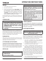
DAMPER HANDLE INSTALLATION
Twist the damper knob clockwise onto the damper rod.
DOOR HANDLE INSTALLATION
1. Slide one of the provided washers onto the door
handle rod.
2. Next slide the wood handle onto the door handle rod.
3. Slide the other provided washer onto the door handle
rod.
4. Screw the provided nut onto the end of the door handle
rod to secure everything in place.

6
© 2023 United States Stove Company
INSTALLATION
SAFETY NOTICE
• IF THIS STOVE IS NOT PROPERLY INSTALLED, A
HOUSE FIRE MAY RESULT. TO REDUCE THE RISK OF
FIRE, FOLLOW THE INSTALLATION INSTRUCTIONS.
• CONTACT YOUR LOCAL BUILDING OFFICIALS TO
OBTAIN A PERMIT AND INFORMATION ON ANY
ADDITIONAL INSTALLATION RESTRICTIONS OR
INSPECTION REQUIREMENTS IN YOUR AREA.
• DO NOT PLACE CLOTHING OR OTHER FLAMMABLE
ITEMS ON OR NEAR THIS STOVE.
• NEVER USE GASOLINE, GASOLINE-TYPE LANTERN
FUEL, KEROSENE, CHARCOAL LIGHTER FLUID, OR
SIMILAR LIQUIDS TO START OR ’FRESHEN UP’
A FIRE IN THIS STOVE. KEEP ALL SUCH LIQUIDS
WELL AWAY FROM THE STOVE WHILE IT IS IN USE.
• THIS APPLIANCE IS A FREESTANDING HEATER.
IT IS NOT INTENDED TO BE ATTACHED TO ANY
TYPE OF DUCTING. IT IS NOT A FURNACE. DO NOT
CONNECT THIS UNIT TO ANY AIR DISTRIBUTION
DUCT OR SYSTEM. THIS APPLIANCE IS NOT
INTENDED FOR COMMERCIAL USE.
• INSTALL VENT AT CLEARANCES SPECIFIED BY THE
VENT MANUFACTURER.
• DO NOT INSTALL A FLUE DAMPER IN THE EXHAUST
VENTING SYSTEM OF THIS UNIT.
• YOUR STOVE REQUIRES PERIODIC MAINTENANCE
AND CLEANING (SEE ”MAINTENANCE”). FAILURE
TO MAINTAIN YOUR STOVE MAY LEAD TO
IMPROPER AND/OR UNSAFE OPERATION.
• A POWER SURGE PROTECTOR IS REQUIRED. THIS
UNIT MUST BE PLUGGED INTO A 110 - 120V, 60
HZ GROUNDED ELECTRICAL OUTLET. DO NOT USE
AN ADAPTER PLUG OR SEVER THE GROUNDING
PLUG. DO NOT ROUTE THE ELECTRICAL CORD
UNDERNEATH, IN FRONT OF, OR OVER THE HEATER.
DO NOT ROUTE THE CORD IN FOOT TRAFFIC AREAS
OR PINCH THE CORD UNDER FURNITURE.
CAUTION:
BURNING FUEL CREATES CARBON MONOXIDE AND
CAN BE HAZARDOUS TO YOUR HEALTH IF NOT
PROPERLY VENTED.
ATTENTION:
• A WORKING SMOKE DETECTOR MUST BE
INSTALLED IN THE SAME ROOM AS THIS PRODUCT.
• INSTALL A SMOKE DETECTOR ON EACH FLOOR OF
YOUR HOME; INCASE OF ACCIDENTAL FIRE FROM
ANY CAUSE IT CAN PROVIDE TIME FOR ESCAPE.
• THE SMOKE DETECTOR MUST BE INSTALLED AT
LEAST 15 FEET (4,57 M) FROM THE APPLIANCE IN
ORDER TO PREVENT UNDUE TRIGGERING OF THE
DETECTOR WHEN RELOADING.
CAUTION:
• USE OF OUTSIDE AIR IS NOT REQUIRED FOR THIS
UNIT.
• DO NOT UNPLUG THE STOVE IF YOU SUSPECT A
MALFUNCTION. TURN THE ON/OFF SWITCH TO
”OFF’ AND CONTACT YOUR DEALER.
• THE HEATER WILL NOT OPERATE DURING A POWER
OUTAGE. IF A POWER OUTAGE DOES OCCUR,
CHECK THE HEATER FOR SMOKE SPILLAGE AND
OPEN A WINDOW IF ANY SMOKE SPILLS INTO THE
ROOM.
• NEVER BLOCK FREE AIRFLOW THROUGH THE OPEN
VENTS OF THE UNIT.
US Stove highly recommends your stove be installed by a
qualied NFI (US) or WETT (Canada) technician. To nd
the nearest qualied installer, go to:
https://ncertied.org,
https://www.wettinc.ca/

© 2023 United States Stove Company
7
INSTALLATION
INSTALLATION OPTIONS
Freestanding Unit - supported by pedestal/legs and
placed on a non-combustible oor surface in compliance
with clearance requirements for a freestanding stove
installation.
Alcove Unit - supported by pedestal/legs and placed
on a non-combustible oor surface in compliance with
clearance requirements for an alcove installation.
IMPROPER INSTALLATION
The use of other components other than stated herein
could cause bodily harm, heater damage, and void your
warranty. The manufacturer will not be held responsible
for damage caused by the malfunction of a stove due to
improper venting or installation.
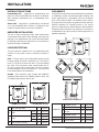
FLOOR PROTECTION
This unit must be installed on a non-combustible oor
surface. If a oor pad is used, it should be certied or
equal.
USA - The oor pad or non-combustible surface should
be large enough to extend a minimum of 6” (153 mm) in
front, 6” (153 mm) on each side, and 1” (26 mm) behind
the stove. Floor protection must extend under and 2”
(51 mm) to each side of the chimney tee for an interior
vertical installation. A Floor Protector of 1” (26 mm) thick
is recommended for this installation.
Canada - Floor protector must comply with CAN/ULC
standards. Must extend 18” (458mm) past the front and
8” (203mm) beyond each side of unit.
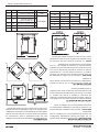
D
B
C
B
A
A Rear (through wall) 1” 25 mm
B Side USA 6” 152 mm
CAN 8” 203mm
C Front USA 6” 152 mm
CAN 18” 458mm
D Rear (interior vertical) 2” 50 mm
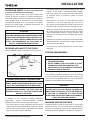
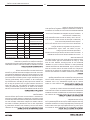
CLEARANCES
Your pellet stove has been tested and listed for installation
in residential, mobile home/transportable building, and
alcove applications in accordance with the clearances
given in this manual. NOTE: The distance on the side of
your pellet stove may need to be greater than the minimum
required clearance for suitable access to the control
panel. For safety reasons, please adhere to the installation
clearances and restrictions. Any reduction in clearance to
combustibles may only be done by means approved by a
regulatory authority.
F
G
E
H
F
G
J
J
J
J
K
PARALLEL
EBackwall to unit 9.5” 241 mm
FSidewall to ue 13” 330 mm
GSidewall to top edge
of unit 8” 203 mm
HBackwall to ue 3” 76.2mm
CORNER JAdjacent wall to unit 8” 203 mm
ALCOVE K Alcove depth 36” 914 mm

8
© 2023 United States Stove Company
OUTSIDE AIR SUPPLY (OPTIONAL, UNLESS INSTALLING
IN A MOBILE HOME/TRANSPORTABLE BUILDING)
Depending on your location and home construction,
outside air may be necessary for optimal performance.
Your stove is approved to be installed with an outside air
intake (69FAK) which is necessary for a mobile home/
transportable building. You can purchase the 69FAK
through your heater dealer. Installation instructions are
supplied with the air intake kit.
ATTENTION:
DO NOT VENT UNDER ANY PORCH, DECK, AWNING,
OR IN ANY SEMI ENCLOSED OR ROOFED AREA. DOING
SO MAY RESULT IN UNPREDICTABLE AIRFLOW AT THE
VENT CAP UNDER CERTAIN CONDITIONS AND CAN
AFFECT THE PERFORMANCE OF YOUR STOVE, AS
WELL AS, OTHER UNFORESEEABLE ISSUES.
SECURING APPLIANCE TO THE FLOOR
Use the designated holes to secure the unit to the oor.
Fresh Air
Intake
Exhaust
Pipe
WARNING! DO NOT INSTALL IN SLEEPING ROOM.
CAUTION! THE STRUCTURAL INTEGRITY OF THE
MOBILE HOME/TRANSPORTABLE BUILDING FLOOR,
WALL, AND CEILING/ROOF MUST BE MAINTAINED.
WHEN INSTALLED IN A MOBILE HOME/
TRANSPORTABLE BUILDING, THE STOVE MUST BE
GROUNDED DIRECTLY TO THE STEEL CHASSIS AND
BOLTED TO THE FLOOR.
In addition to the previously detailed installation
requirements, mobile home/transportable building
installations must meet the following requirements:
• This stove must be securely fastened to the oor of the
mobile home/transportable building using two 1/4” lag
bolts that are long enough to go through both a hearth
pad, if used, and the oor of the home.
• The heater must be electrically grounded to the steel
chassis of the mobile home/transportable building
with 8 GA copper wire using a serrated or star washer
to penetrate paint or protective coating to ensure
grounding.
• Vent must be 3 or 4-inch “PL” Vent and must extend
a minimum or 36” (914 mm) above the roof line of
the mobile home/transportable building and must be
installed using a certied ceiling re stop and rain cap.
• When moving your mobile home/transportable building,
all exterior venting must be removed while the mobile
home/transportable building is being relocated. After
relocation, all venting must be reinstalled and securely
fastened.
• Outside Air is mandatory for mobile home/transportable
building installation. See Outside Air Supply section and
your dealer for purchasing.
• Check with your local building ocials as other codes
may apply.
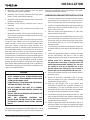
VENTING REQUIREMENTS
WARNING:
• INSTALL VENT AT CLEARANCES SPECIFIED BY THE
VENT MANUFACTURER.
• DO NOT CONNECT THE PELLET VENT TO A VENT
SERVING ANY OTHER APPLIANCE OR STOVE.
• DO NOT INSTALL A FLUE DAMPER IN THE EXHAUST
VENTING SYSTEM OF THIS UNIT.
The following installation guidelines must be followed
to ensure conformity with both the safety listing of this
stove and to local building codes. Do not use makeshift
methods or compromise in the installation.
IMPORTANT:
THIS UNIT IS EQUIPPED WITH A NEGATIVE DRAFT
SYSTEM THAT PULLS AIR THROUGH THE BURN POT
AND PUSHES THE EXHAUST OUT OF THE DWELLING.
IF THIS UNIT IS CONNECTED TO A FLUE SYSTEM
OTHER THAN THE WAY EXPLAINED IN THIS MANUAL,
IT WILL NOT FUNCTION PROPERLY.
MAXIMUM VENTING DISTANCE
Installation MUST include at least 3-feet of vertical pipe
outside the home. This will create some natural draft to
reduce the possibility of smoke or odor during appliance
shutdown and keep exhaust from causing a nuisance or
INSTALLATION

© 2023 United States Stove Company
9
hazard by exposing people or shrubs to high temperatures.
The maximum recommend vertical venting height is 12-
feet for 3-inch type “PL” vent. Total length of horizontal vent
must not exceed 4-feet. This could cause back pressure.
Use no more than 180 degrees of elbows (two 90-degree
elbows, or two 45-degree and one 90-degree elbow, etc.)
to maintain adequate draft.
IMPORTANCE OF PROPER DRAFT
Draft is the force which moves air from the appliance up
through the chimney. The amount of draft in your chimney
depends on the length of the chimney, local geography,
nearby obstructions and other factors. Too much draft
may cause excessive temperatures in the appliance.
Inadequate draft may cause backpung into the room and
‘plugging’ of the chimney. Inadequate draft will cause the
appliance to leak smoke into the room through appliance
and chimney connector joints. An uncontrollable burn or
excessive temperature indicates excessive draft. Take into
account the chimney’s location to ensure it is not too close
to neighbours or in a valley which may cause unhealthy or
nuisance conditions.
PELLET VENT TYPE
A certied 3-inch or 4-inch type “PL” pellet vent exhaust
system must be used for installation and attached to the
pipe connector provided on the back of the stove (use a
3-inch to 4-inch adapter for 4-inch pipe). The connection
at the back of the stove must be sealed using Hi-Temp
RTV. Use a 4-inch vent if the vent height is over 12-feet or
if the installation is over 2,500 feet above sea level. We
recommend the use of Simpson Dura-Vent® or Metal-
Fab® pipe (if you use other pipes, consult your local
building codes and/or building inspectors). Do not use
Type-B Gas Vent pipe or galvanized pipe with this unit. The
pellet vent pipe is designed to disassemble for cleaning
and should be checked several times during the burning
season. The pellet vent pipe is not furnished with the unit
and must be purchased separately.
PELLET VENT INSTALLATION
The installation must include a clean-out tee to enable
collection of y ash and to permit periodic cleaning of the
exhaust system. 90-degree elbows accumulate y ash
and soot thereby reducing exhaust ow and performance
of the stove. Each elbow or tee reduces draft potential by
30% to 50%. All joints in the vent system must be fastened
by at least 3 screws, and all joints must be sealed with Hi-
Temp RTV silicone sealant to be airtight. The area where
the vent pipe penetrates to the exterior of the home must
be sealed with silicone or other means to maintain the
vapor barrier between the exterior and the interior of the
home. Vent surfaces can get hot enough to cause burns if
touched by children. Noncombustible shielding or guards
may be required.
PELLET VENT TERMINATION
Do not terminate the vent in an enclosed or semi-enclosed
area, such as; carport, garage, attic, crawl space, under a
sun deck or porch, narrow walkway, or any other location
that can build up a concentration of fumes. Termination in
one of these areas can also lead to unpredictable pressure
situations with the appliance, and could result in improper
performance and/or malfunction. The termination
must exhaust above the outside air inlet elevation. The
termination must not be located where it will become
plugged by snow or other materials. Do not terminate the
venting into an existing steel or masonry chimney.
VENT TERMINATION CLEARANCES
A. Minimum 4-foot (1.22m) clearance below or beside
any door or window that opens.
B. Minimum 1-foot (0.3m) clearance above any door or
window that opens.
C. Minimum 3-foot (0.91m) clearance from any adjacent
building.
INSTALLATION

10
© 2023 United States Stove Company
D. Minimum 7-foot (2.13m) clearance from any grade
when adjacent to public walkways.
E. Minimum 2-foot (0.61m) clearance above any grass,
plants, or other combustible materials.
F. Minimum 3-foot (0.91m) clearance from an forced air
intake of any appliance.
G. Minimum 2-foot (0.61m) clearance below eves or
overhang.
H. Minimum 1-foot (0.3m) clearance horizontally from
combustible wall.
I. Must be a minimum of 3 foot (0.91m) above the roof
and 2 foot (0.61m) above the highest point or the roof
within 10 feet (3.05m).
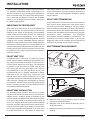
Determining where to install your new pellet stove heater.
To get the most ecient use of re-circulated heat, you
should consider a room that is centrally located within
your home. Choose a room that is large and open. It is
Extremely Important to maintain proper clearances from
any combustible surfaces or materials in the room where
your heater will be located. You can nd proper clearance
measurements in this manual and on the rating label of
your pellet stove. The pellet stove can be vented through an
exterior wall or into an existing masonry or metal chimney
if “PL” vent pipe is used throughout existing chimney.
Venting can pass through the ceiling and roof if approved
pipe is used. Where passage through a wall, or partition of
combustible construction is desired, the installation must
conform to CAN/CSA-B365.
WARNING:
• DO NOT OBTAIN COMBUSTION AIR FROM THE
ATTIC, GARAGE OR ANY OTHER UNVENTILATED
AREA. YOU MAY OBTAIN COMBUSTION AIR FROM
A VENTILATED CRAWL SPACE.
• DO NOT INSTALL A FLUE DAMPER IN THE EXHAUST
VENTING SYSTEM OF THIS UNIT.
• DO NOT CONNECT THIS UNIT TO A CHIMNEY
FLUE SERVING ANOTHER HEATER, FURNACE OR
APPLIANCE.
• INSTALL VENT AT CLEARANCES SPECIFIED BY THE
VENT MANUFACTURER.
• ONLY USE APPROVED MATERIAL FOR
INSTALLATION, FAILURE TO DO SO MAY RESULT
IN PROPERTY DAMAGE, BODILY INJURY, OR EVEN
DEATH.
This appliance is certied for use with listed 3 inch or 4 inch
“PL” pellet venting products. The use of other components
other than stated herein could cause bodily harm, heater
damage, and void your warranty.
HORIZONTAL EXHAUST VENT INSTALLATION
1. Locate your pellet stove in a location which meets the
requirements of this manual, but in an area where it
does not interfere with the house framing, wiring, etc.
2. Install a non-combustible hearth pad underneath the
pellet stove. This pad should extend at least 6” (152
mm) in front of the unit.
3. Place the pellet stove approximately 15” (381 mm)
away from the interior wall.
4. Locate the center of the exhaust pipe of your unit. This
point should then be extended to the interior wall of
your house. Once you have located the center point,
on the interior wall, cut a 7” (175 mm) diameter hole
through the wall.
5. The next step is to install the wall thimble, refer to the
instructions which come with the wall thimble for this
step.
6. Install the appropriate length of exhaust vent pipe
into the wall thimble. See steps 11 and 12 when
determining the correct length of exhaust vent to use.
7. Outside Fresh Air is Mandatory when installing
this pellet stove room heater in airtight homes and
mobile home/transportable buildings. Be sure that
the outside air vent has an approved cap on it to
prevent rodents from entering. Be sure to install in
location that won’t become blocked with snow, etc.
8. Connect the exhaust vent pipe to the exhaust outlet of
your pellet stove.
9. Secure all vent joint connections with 3 screws.
Seal the exhaust vent joint connections with high
temperature silicone sealant.
10. Push the unit straight back to the interior wall,
being sure to maintain the minimum clearances to
combustibles 2” (51 mm) to the back of the unit. Seal
the annular space of the wall thimble and around the
vent pipe with high temperature silicone sealant.
11. The exhaust vent pipe must extend at least 12” (300
mm) out past the exterior wall. Seal the annular space
of the wall thimble and around the vent pipe with high
temperature silicone sealant.
12. Install an approved horizontal termination cap or if
necessary install a 90° elbow and appropriate length
of vertical venting. An approved vertical vent cap is
recommended.
INSTALLATION

© 2023 United States Stove Company
11
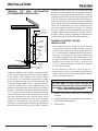
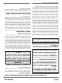
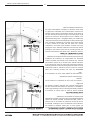
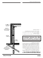
THROUGH THE WALL INSTALLATION
(RECOMMENDED INSTALLATION)
Non-Combustable
Floor Pad
Clean-Out
Cover
Tee
Wall
Thimble
Pipe
Adapter
Exhaust Motor
Adapter
3’-0” (min) Vertical Pipe
Support
Bracket
Termination
Cap
90° Elbow
TO STOVE
Canadian installations must conform to CAN/CSA-B365.
To vent the unit through the wall, connect the pipe adapter
to the exhaust motor adapter. If the exhaust adapter
is at least 18” (457 mm) above ground level, a straight
section of pellet vent pipe can be used through the wall.
Your heater dealer should be able to provide you with a
kit that will handle most of this installation, which will
include a wall thimble that will allow the proper clearance
through a combustible wall. Once outside the structure,
a 3” (76 mm) clearance should be maintained from the
outside wall and a clean out tee should be placed on the
pipe with a 90-degree turn away from the house. At this
point, a 3ft (0.91m) (minimum) section of pipe should be
added with a horizontal cap, which would complete the
installation. A support bracket should be placed just below
the termination cap or one every 4ft (1.22m) to make the
system more stable. If you live in an area that has heavy
snowfall, it is recommended that the installation be taller
than 3ft (0.91m) to get above the snowdrift line. This same
installation can be used if your heater is below ground level
by simply adding the clean-out section and vertical pipe
inside until ground level is reached. With this installation
you have to be aware of the snowdrift line, dead grass, and
leaves. We recommend a 3ft (0.91m) minimum vertical
rise on the inside or outside of the house. The “through
the wall” installation is the least expensive and simplest
installation. Never terminate the end vent under a deck, in
an alcove, under a window, or between two windows. We
recommend Simpson Dura-Vent® or Metal-Fab® kits.
THROUGH THE ROOF / CEILING
INSTALLATION
• When venting the heater through the ceiling, the pipe
is connected the same as through the wall, except the
clean-out tee is always on the inside of the house, and
a 3” (76 mm) adapter is added before the clean-out tee.
• You must use the proper ceiling support anges and
roof ashing (supplied by the pipe manufacturer; follow
the pipe manufacturer’s directions). It is important to
note that if your vertical run of pipe is more than 12ft
(3.7m), the pellet vent pipe size should be increased to
4” (102 mm) in diameter.
• Do not exceed more than 4ft (1.22m) of pipe on a
horizontal run and use as few elbows as possible. If an
offset is required, it is better to install 45-degree elbows
rather than 90-degree elbows.
WARNING:
YOU MAY WANT TO LOCATE ANY UTILITIES OR
OBSTACLES INSIDE THE WALL BEFORE ATTEMPTING
THIS INSTALL. MAKE SURE TO KEEP IN MIND YOUR
UNIT’S CLEARANCE REQUIREMENTS.
1. Mark the area and then cut the wall for vent installation
if needed.
2. Install the wall thimble as specied by the manufacturer
(wall thimble sold separately)
3. Install venting.
INSTALLATION

12
© 2023 United States Stove Company
INSTALLATION
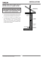
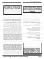
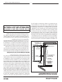
VENTING YOUR PELLET STOVE INTO AN
EXISTING CLASS A 6” CHIMNEY SYSTEM
IMPORTANT:
IF YOU ARE INSTALLING YOUR PELLET STOVE AS
A REPLACEMENT TO AN EXISTING WOOD STOVE,
YOU CAN INSTALL YOUR PELLET STOVE USING THE
EXISTING CLASS A 6” VENTING SYSTEM.
1. You must have the existing chimney system cleaned
and/ or inspected by a qualied chimney sweep before
proceeding with the installation of your pellet stove.
2. To the right is an example of an installation using
part number 860001, 3-6” transition into 6” connector
pipe. The illustration is only an example. Please
conform to any local building codes or regulations
having jurisdiction before you have a qualied installer
proceed with this installation.
Existing Class ‘A’
6” Chimney System
3” PL Vent
Clean Out Tee
Support
Bracket
Ceiling
Support
3” to 6” Pipe
Adapter
TO STOVE

© 2023 United States Stove Company
13
NEVER OPERATE THIS PRODUCT WHILE UNATTENDED
OPERATION INSTRUCTIONS
HOW YOUR HEATER WORKS
Your pellet heater operates on a timer based auger fuel
feed system, that is controlled by a digital circuit board.
The fuel is delivered from the auger into a burn pot, which
is the vessel where the combustion process takes place.
Based upon the heat ranges (1-5), the heater will feed the
appropriate amount of fuel to reach a set temperature
range. Note that the amount of heat produced by the heater
is proportional to the rate of the fuel that is burned. Your
heater is equipped with an automatic ignition system that
should ignite the fuel within 5-10 minutes from pressing
the ON button. As pellets fall into the burn pot and ignite,
outside air is drawn in to feed the re by a combustion
blower. The post combustion gases are then pulled through
the heat exchanger as they are traveling out the exhaust.
As the heater warms up, room air is circulated around the
heat exchanger by means of a room air blower, distributing
warm air into the room. Because a forced draft pressure
is required for the combustion process inside your heater,
it is extremely important that the exhaust system be
properly maintained. And, that when operating your heater,
you make sure that the viewing and combustion doors are
properly closed and/or sealed.
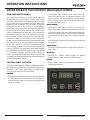
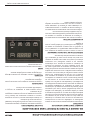
CONTROL PANEL OVERVIEW
Turning the heater ON/OFF, as well as adjustments for the
fuel feed rate is performed by pressing the appropriate
button(s) on the control panel which is located on the
front, lower left-hand corner of your heater.
ON/OFF
• Pressing the “ON” button on the control panel will begin
the start-up sequence for the heater. Fuel will begin to
feed through the auger feed system then ignite after
approx. 5 minutes.
• Pressing the “OFF” button on the control panel will
cause the heater to enter its shut-down sequence. The
fuel feed system will stop pulling fuel from the hopper
and, once the re goes out and the heater cools down,
the fans will stop running.
HEAT RANGE
• Pressing the “Heat Range” arrows, up or down, will
adjust the amount of fuel being delivered to the burn pot.
• The exhaust blower will start. Note that this appliance
pulses the exhaust blower in order to achieve the proper
air to fuel ratio, and to also aid in the cleaning of the burn
pot.
• Once the heater reaches a set temperature, the room fan
will come on.
CONFIGURE
• Press the “Congure” button to begin pairing the unit to
your phone.
DISPLAY
• Pressing the “Display” button toggles the display
between the heat range and the room temperature.
MODE
• Use the “Mode” button to switch between manual mode
and thermostat mode.

14
© 2023 United States Stove Company
WARNING:
• DO NOT USE CHEMICALS OR FLUIDS TO START
THE FIRE - NEVER USE GASOLINE, GASOLINE-
TYPE LANTERN FUEL, KEROSENE, CHARCOAL
LIGHTER FLUID, OR SIMILAR LIQUIDS TO START
OR “FRESHEN UP” A FIRE IN THIS STOVE. KEEP
ALL SUCH LIQUIDS WELL AWAY FROM THE STOVE
WHILE IT IS IN USE.
• HOT WHILE IN OPERATION. KEEP CHILDREN,
CLOTHING AND FURNITURE AWAY. CONTACT MAY
CAUSE SKIN BURNS.
This heater is designed to burn only PFI Premium grade
pellets. DO NOT BURN:
1. Garbage;
2. Lawn clippings or yard waste;
3. Materials containing rubber, including tires;
4. Materials containing plastic;
5. Waste petroleum products, paints or paint thinners, or
asphalt products;
6. Materials containing asbestos;
7. Construction or demolition debris;
8. Railroad ties or pressure-treated wood;
9. Manure or animal remains;
10. Salt water driftwood or other previously salt water
saturated materials;
11. Unseasoned wood; or
12. Paper products, cardboard, plywood, or particleboard.
The prohibition against burning these materials does
not prohibit the use of re starters made from paper,
cardboard, saw dust, wax and similar substances
for the purpose of starting a re in an affected wood
heater.
Burning these materials may result in release of toxic
fumes or render the heater ineffective and cause smoke.
PROPER FUEL
ATTENTION:
THIS APPLIANCE IS DESIGNED FOR THE USE OF
PELLETIZED FUEL THAT MEET OR EXCEED THE
STANDARD SET BY THE PELLET FUEL INSTITUTE
(PFI).
Your pellet stove is designed to burn premium hardwood
pellets that comply with the Pellet Fuels Institute (PFI)
standard (minimum of 40 lbs density per cubic ft, 1/4” to
5/16” diameter, length no greater than 1.5”, not less than
8,200 BTU/lb, moisture under 8% by weight, ash under 1%
by weight, and salt under 300 parts per million). Pellets
that are soft, contain excessive amounts of loose sawdust,
have been, or are wet, will result in reduced performance.
Store your pellets in a dry place. DO NOT store the fuel
within the installation clearances of the unit or within the
space required for refuelling and ash removal. Doing so
could result in a house re. Do not over re or use volatile
fuels or combustibles, doing so may cause a personal and
property damage hazards.
THIS STOVE IS APPROVED FOR BURNING PELLETIZED
WOOD FUEL ONLY ! Factory-approved pellets are those
1/4” or 5/16” in diameter and not over 1” long. Longer or
thicker pellets sometimes bridge the auger ights, which
prevents proper pellet feed. Burning wood in forms other
than pellets is not permitted. It will violate the building
codes for which the stove has been approved and will void
all warranties. The design incorporates automatic feed of
the pellet fuel into the re at a carefully prescribed rate. Any
additional fuel introduced by hand will not increase heat
output but may seriously impair the stoves performance
by generating considerable smoke. Do not burn wet
pellets. The stove’s performance depends heavily on the
quality of your pellet fuel. Avoid pellet brands that display
these characteristics:
• Excess Fines – “Fines” is a term describing crushed
pellets or loose material that looks like sawdust or sand.
Pellets can be screened before being placed in hopper
to remove most nes.
• Binders – Some pellets are produced with materials to
hold the together, or “bind” them.
• High ash content – Poor quality pellets will often create
smoke and dirty glass. They will create a need for more
frequent maintenance. You will have to empty the burn
pot plus vacuum the entire system more often. Poor
quality pellets could damage the auger. We cannot
accept responsibility for damage due to poor quality
pellet.
CAUTION:
• KEEP FOREIGN OBJECTS OUT OF THE HOPPER.
• THE MOVING PARTS OF THIS STOVE ARE
PROPELLED BY HIGH TORQUE ELECTRIC MOTORS.
KEEP ALL BODY PARTS AWAY FROM THE
AUGER WHILE THE STOVE IS PLUGGED INTO AN
ELECTRICAL OUTLET. THESE MOVING PARTS MAY
BEGIN TO MOVE AT ANY TIME WHILE THE STOVE
IS PLUGGED IN.
OPERATION INSTRUCTIONS

© 2023 United States Stove Company
15
PRE-START-UP CHECK
Remove burn pot, making sure it is clean and none of the
air holes are plugged. Clean the rebox, and then reinstall
burn pot. Clean door glass if necessary (a dry cloth or
paper towel is usually sucient). Never use abrasive
cleaners on the glass or door. Check fuel in the hopper,
and rell if necessary.
BUILDING A FIRE
Never use a grate or other means of supporting the fuel.
Use only the burn pot supplied with this heater. Hopper lid
must be closed in order for the unit to feed pellets. During
the start-up period:
• Make sure the burn pot is free of pellets.
• DO NOT open the viewing door.
• DO NOT add pellets to the burn pot by hand.
NOTE: During the rst few res, your stove will emit an odor
as the high-temperature paint cures or becomes seasoned
to the metal. Maintaining smaller res will minimize this.
Avoid placing items on the stovetop during this period
because the paint could be affected. Attempts to achieve
heat output rates that exceed heater design specications
can result in permanent damage to the heater.
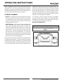
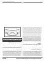
OPTIMAL OPERATION
This pellet stove has been certied by the US EPA to
meet strict 2020 guidelines. To Insure this unit produces
the optimal minimal emissions, it is critical to follow
the following guidelines. To achieve a “high burn” your
stove should be set on setting 5 with the damper open.
To achieve a “medium burn” your stove should be set on
setting 3 with the damper 50% open. To achieve a “low
burn” your stove should be set on setting 1with the damper
closed. If the door is opened while the stove is in operation
it must be closed within 30 seconds or the stove will shut
down. If the stove shuts down push the “On/Off” button to
re-start your stove. The stove will have to fully shut down
and turn off before you will be able to restart the stove.
DAMPER SETTINGS
Fully Open
Fully Closed
OPERATION INSTRUCTIONS

16
© 2023 United States Stove Company
IGNITOR
1. Fill the hopper and clean the burn pot.
2. Press the “On/Off” button.
3. Set the heat range/temperature. Manual Mode - Press
the “Display Button” to see the current heat range. Use
the up and down arrows to adjust the heat range.
T-stat Mode - Press the “Display Button” to see the
current temperature setting. Use the up and down
arrows to adjust the temperature as needed.
If the re doesn’t start in 12 minutes, press “On/Off”, wait
a few minutes, clear the burn pot, and start the procedure
again.
OPENING DOOR
CAUTION:
• DO NOT OPERATE YOUR STOVE WITH THE VIEWING
DOOR OPEN. THE AUGER WILL NOT FEED PELLETS
UNDER THESE CIRCUMSTANCES AND A SAFETY
CONCERN MAY ARISE FROM SPARKS OR FUMES
ENTERING THE ROOM.
• THE DOOR MUST BE CLOSED AND SEALED DURING
OPERATION.
If the door is opened while the stove is in operation it must
be closed within 30 seconds or the stove will shut down. If
the stove shuts down push the “On/Off” button to re-start
your stove. The stove will have to fully shut down and turn
off before you will be able to restart the stove.
ROOM AIR FAN
When starting your stove the Room Air Fan will not come
on until the stove’s heat exchanger warms up. This usually
takes about 10 minutes from start-up.
IF STOVE RUNS OUT OF PELLETS
The re goes out and the auger motor and blowers will run
until the stove cools. This will take 30 minutes or longer
depending on the heat remaining in the appliance. After
the stove components stop running all lights on the display
will go out and the two digit display will begin ashing “E3”
REFUELLING
WARNING:
• KEEP HOPPER LID CLOSED AT ALL TIMES EXCEPT
WHEN REFILLING.
• DO NOT OVERFILL HOPPER.
CAUTION:
• THE HOPPER AND STOVE TOP WILL BE HOT
DURING OPERATION; THEREFORE, YOU SHOULD
ALWAYS USE SOME TYPE OF HAND PROTECTION
WHEN REFUELING YOUR STOVE.
• DO NOT TOUCH THE HOT SURFACES OF THE STOVE.
EDUCATE ALL CHILDREN ON THE DANGERS OF A
HIGH-TEMPERATURE STOVE. YOUNG CHILDREN
SHOULD BE SUPERVISED WHEN THEY ARE IN THE
SAME ROOM AS THE STOVE.
• NEVER PLACE YOUR HAND NEAR THE AUGER
WHILE THE STOVE IS IN OPERATION.
• WE RECOMMEND THAT YOU NOT LET THE HOPPER
DROP BELOW 1/4 FULL.
TAMPER WARNING
This wood heater has a manufacturer-set minimum low
burn rate that must not be altered. It is against federal
regulations to alter this setting or otherwise operate this
wood heater in a manner inconsistent with operating
instructions in this manual.
SHUTDOWN PROCEDURE
WARNING:
NEVER SHUT DOWN THIS UNIT BY UNPLUGGING IT
FROM THE POWER SOURCE.
Turning your stove off is a matter of pressing the “POWER”
button on the display board. The auger motor will stop,
and the blowers will continue to operate until the internal
rebox temperatures have fallen to a preset level.
1. Your stove is equipped with a high temperature
thermodisc. This unit has a manual reset thermodisc.
This safety switch has two functions.
A. To recognize an overheat situation in the stove and
shut down the fuel feed or auger system.
B. In case of a malfunctioning convection blower, the
high-temperature thermodisc will automatically shut
down the auger, preventing the stove from overheating.
NOTE: On some units, once tripped, like a circuit breaker,
the reset button will have to be pushed before restarting
your stove. On other units the thermodisc has no reset
button and will reset itself once the stove has cooled. The
manufacturer recommends that you call your dealer if this
occurs as this may indicate a more serious problem. A
service call may be required.
2. If the combustion blower fails, an air pressure switch
will automatically shut down the auger.
OPERATION INSTRUCTIONS

© 2023 United States Stove Company
17
OPERATION INSTRUCTIONS
NOTE: Opening the stove door for more than 30 seconds
during operation will cause enough pressure change to
activate the air switch, shutting the fuel feed off. The stove
will shut down and show “E2” on the two digit display. The
stove has to fully shut down before restarting.
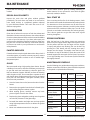
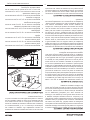
INTERIOR CHAMBERS
• Burn Pot - Periodically remove and clean the burn pot
and the area inside the burn pot housing. In particular,
it is advisable to clean out the holes in the burn pot to
remove any build up that may prevent air from moving
through the burn pot freely.
• Heat Exchanger - There are two clean out plates that
need to be removed in order to clean the y ash out
of the heat exchanger. Open the door to access the
cleanouts located inside the rebox, one on each side
of the burnpot. The clean outs are secured to the rebox
with (2) 5/16” screws each. Remove the clean outs
and vacuum out any accumulated ash. This should be
done at least once per month or more frequently if large
amounts of ash are noticed while cleaning or if the stove
does not seem to be burning properly.
Over time ash or dust may accumulate on the blades of the
circulation & exhaust fans. The fans should be inspected,
periodically, and if any accumulation is present vacuumed
clean as the ash or dust can impede the fans performance.
It is also possible that creosote may accumulate in the
exhaust fan therefore, this must be brushed clean. The
exhaust fan can be found behind the left side panel (facing
the front of the heater), the circulation fan can be found
behind the right side panel. To access the igniter, remove
the air inlet tube and cover (2 screws). The auger motor is
located in the center rear of the unit. Note: When cleaning,
take care not to damage the fan blades.
If a vacuum is used to clean your stove, we suggest
using the AV15E AshVac vacuum. The AV15E AshVac is
designed for ash removal. Some regular vacuum cleaner
(i.e. shop vacs) may leak ash into the room.
DO NOT VACUUM HOT ASH.
WARNING:
FAILURE TO PROPERLY MAINTENANCE THE CLEAN
OUTS WILL RESULT IN POOR PERFORMANCE OF THIS
STOVE.
Clean-Out Plates

18
© 2023 United States Stove Company
NEVER OPERATE THIS PRODUCT WHILE UNATTENDED
MAINTENANCE
CAUTION:
• FAILURE TO CLEAN AND MAINTAIN THIS UNIT AS
INDICATED CAN RESULT IN POOR PERFORMANCE,
SAFETY HAZARDS, FIRE, AND EVEN DEATH.
• NEVER PERFORM ANY INSPECTIONS, CLEANING,
OR MAINTENANCE ON A HOT STOVE.
• DISCONNECT THE POWER CORD BEFORE
PERFORMING ANY MAINTENANCE! NOTE:
TURNING THE ON/OFF SWITCH TO ”OFF” DOES NOT
DISCONNECT ALL POWER TO THE ELECTRICAL
COMPONENTS OF THE STOVE.
• DO NOT OPERATE STOVE WITH BROKEN GLASS,
LEAKAGE OF FLUE GAS MAY RESULT.
• ATTEMPTS TO ACHIEVE HEAT OUTPUT RATES
THAT EXCEED HEATER DESIGN SPECIFICATIONS
CAN RESULT IN PERMANENT DAMAGE TO THE
HEATER.
CREOSOTE FORMATION, INSPECTION, &
REMOVAL
CAUTION:
THE EXHAUST SYSTEM SHOULD BE CHECKED
MONTHLY DURING THE BURNING SEASON FOR ANY
BUILD-UP OF SOOT OR CREOSOTE.
When any wood is burned slowly, it produces tar and other
organic vapors, which combine with expelled moisture
to form creosote. The creosote vapors condense in the
relatively cool chimney ue or a newly started re or
from a slow-burning re. As a result, creosote residue
accumulates on the ue lining. When ignited, this creosote
makes an extremely hot re, which may damage the
chimney or even destroy the house. Despite their high
eciency, pellet stoves can accumulate creosote under
certain conditions. The chimney connector and chimney
should be inspected by a qualied person annually or per
ton of pellets to determine if a creosote or y ash build-up
has occurred. If creosote has accumulated, it should be
removed to reduce the risk of a chimney re. Inspect the
system at the stove connection and at the chimney top.
Cooler surfaces tend to build creosote deposits quicker, so
it is important to check the chimney from the top as well as
from the bottom. The creosote should be removed with a
brush specically designed for the type of chimney in use.
A qualied chimney sweep can perform this service. It is
also recommended that before each heating season the
entire system be professionally inspected, cleaned and, if
necessary, repaired. To clean the chimney, disconnect the
vent from the stove.
FLY ASH
This accumulates in the horizontal portion of an exhaust
run. Though non-combustible, it may impede the normal
exhaust ow. It should therefore be periodically removed.
ASH REMOVAL & DISPOSAL
CAUTION:
ALLOW THE STOVE TO COOL BEFORE PERFORMING
ANY MAINTENANCE OR CLEANING. ASHES MUST BE
DISPOSED IN A METAL CONTAINER WITH A TIGHT
FITTING LID. THE CLOSED CONTAINER OF ASHES
SHOULD BE PLACED ON A NON-COMBUSTIBLE
SURFACE OR ON THE GROUND, WELL AWAY FROM
ALL COMBUSTIBLE MATERIALS, PENDING FINAL
DISPOSAL.
Remove the ashes periodically to avoid unnecessary ash
build up. Remove ashes when unit has cooled. Ashes
should be placed in a metal container with a tight tting
lid. The closed container of ashes should be placed
on a noncombustible oor or on the ground, well away
from all combustible materials, pending nal disposal. If
the ashes are disposed of by burial in soil or otherwise
locally dispersed, they should be retained in the closed
container until all embers have been thoroughly cooled.
The container shall not be used for other trash or waste
disposal. If combined with combustible substances, ashes
and embers may ignite.
SMOKE & CO MONITORS
Burning wood naturally produces smoke and carbon
monoxide(CO) emissions. CO is a poisonous gas
when exposed to elevated concentrations for extended
periods of time. While the modern combustion systems
in heaters drastically reduce the amount of CO emitted
out the chimney, exposure to the gases in closed or
conned areas can be dangerous. Make sure you stove
gaskets and chimney joints are in good working order
and sealing properly to ensure unintended exposure. It is
recommended that you use both smoke and CO monitors
in areas having the potential to generate CO.
CHECK & CLEAN THE HOPPER
Check the hopper periodically to determine if there is any
sawdust (nes) that is building up in the feed system or

© 2023 United States Stove Company
19
MAINTENANCE
pellets that are sticking to the hopper surface. Clean as
needed.
DOOR & GLASS GASKETS
Inspect the main door and glass window gaskets
periodically. The main door may need to be removed to
have frayed, broken, or compacted gaskets replaced
by your authorized dealer. This unit’s door uses a 3/4”
diameter rope gasket.
BLOWER MOTORS
Clean the air holes on the motors of both the exhaust and
distribution blowers annually. Remove the exhaust blower
from the exhaust duct and clean out the internal fan blades
as part of your fall start-up. If you have indoor pets your
power motors should be inspected monthly to make sure
they are free of animal hair build up. Animal hair build up
in blowers can result in poor performance or unforeseen
safety hazards.
PAINTED SURFACES
Painted surfaces may be wiped down with a damp cloth. If
scratches appear, or you wish to renew your paint, contact
your authorized dealer to obtain a can of suitable high-
temperature paint.
GLASS
We recommend using a high-quality glass cleaner. Should
a buildup of creosote or carbon accumulate, you may wish
to use 000 steel wool and water to clean the glass. DO
NOT use abrasive cleaners. DO NOT perform the cleaning
while the glass is HOT. Do not attempt to operate the unit
with broken glass. Replacement glass may be purchased
from your U.S. Stove dealer. If the glass is broken, follow
these removal procedures:
1. Once the heater has cooled, remove the door from the
heater.
2. Remove the rope gasket from the door followed by the
nuts holding the glass retainer in place.
3. While wearing gloves, carefully remove any loose
pieces of glass from the door frame.
4. Replace the glass and gasket, making sure the gasket
runs the full perimeter of the glass edge.
5. Re-install the retainer and eight nuts and rope gasket
using high-temperature silicone to adhere the gasket
to the door.
6. Never use substitute materials for the glass.
DO NOT abuse the door glass by striking, slamming, or
similar trauma. Do not operate the stove with the glass
removed, cracked, or broken.
FALL START UP
Prior to starting the rst re of the heating season, check
the outside area around the exhaust and air intake systems
for obstructions. Clean and remove any y ash from the
exhaust venting system. Clean any screens on the exhaust
system and on the outside air intake pipe. Turn all of the
controls on and make sure that they are working properly.
This is also a good time to give the entire stove a good
cleaning throughout.
SPRING SHUTDOWN
After the last burn in the spring, remove any remaining
pellets from the hopper and the auger feed system. Scoop
out the pellets and then run the auger until the hopper
is empty and pellets stop owing (this can be done by
pressing the “ON” button with the viewing door open).
Vacuum out the hopper. Thoroughly clean the burn pot,
and rebox. It may be desirable to spray the inside of the
cleaned hopper with an aerosol silicone spray if your stove
is in a high humidity area. The exhaust system should be
thoroughly cleaned.
MAINTENANCE SCHEDULE
Use the following as a guide under average use conditions.
Gaskets around door and door glass should be inspected
and repaired or replaced when necessary.
Daily Weekly Monthly or
as needed
Burn Pot Stirred Empty
Combustion
Chamber Brushed
Ashes Check Empty
Interior Chambers Vacuumed
Combustion
Blower Blades
Vacuumed /
Brushed
Convection Blower
Impeller
Vacuumed /
Brushed
Vent System Cleaned
Gaskets Inspected
Glass Wiped Cleaned
Hopper (end of
season)
Empty &
Vacuumed

20
© 2023 United States Stove Company
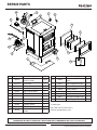
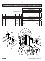
HOW TO ORDER REPAIR PARTS
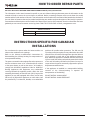
INSTRUCTIONS SPECIFIC FOR CANADIAN
INSTALLATIONS
Do not obstruct the space under the heater and do not
obstruct the combustion air openings.
Refer to the chimney manufacturer’s instructions for
disassembling the chimney/venting for transportation of
a transportable building.
The parts or materials to be employed for ember protectors
and the minimum areas to be covered and their relation
to the space heater, as well as the notice: “In Canada, to
comply with CSA B365, Installation Code for Solid-Fuel-
Burning Appliances and Equipment, any combustible
covering beneath the appliance and/or within the area
extending horizontally at least 450 mm (18 in) beyond the
appliance on any side equipped with a door, and at least
200 mm (8 in) beyond the appliance on other sides, shall
be protected by a continuous, durable, non-combustible
pad that will provide ember protection. The 450 mm (18
in) ember protection required on any side with a door shall
extend for the full width of the appliance plus the 200 mm
(8 in) required on each side of the appliance without a
door. Where an appliance is installed less than 200 mm (8
in) from a wall, the ember pad need only extend to the base
of the wall. An ember pad shall not be placed on top of a
carpet unless the pad is structurally supported to prevent
displacement and distortion.
If this appliance is installed in a transportable building,
removal of the chimney/venting is required for
transportation of the building.
DO NOT INSTALL IN AN ALCOVE
DO NOT INSTALL IN ANY FIREPLACE
For Parts Assistance Call: 800-750-2723 Ext 5051 or Email: parts@usstove.com
The information in this owner’s manual is specic to your unit. When ordering replacement parts the information in this
manual will help to ensure the correct items are ordered. Before contacting customer service write down the model
number and the serial number of this unit. That information can be found on the certication label attached to the back of
the unit. Other information that may be needed would be the part number and part description of the item(s) in question.
Part numbers and descriptions can be found in the “Repair Parts” section of this manual. Once this information has been
gathered you can contact customer service by phone 1-800-750-2723 Ext 5051 or Email [email protected].
Model Information
Model Number
Serial Number
La page est en cours de chargement...
La page est en cours de chargement...
La page est en cours de chargement...
La page est en cours de chargement...
La page est en cours de chargement...
La page est en cours de chargement...
La page est en cours de chargement...
La page est en cours de chargement...
La page est en cours de chargement...
La page est en cours de chargement...
La page est en cours de chargement...
La page est en cours de chargement...
La page est en cours de chargement...
La page est en cours de chargement...
La page est en cours de chargement...
La page est en cours de chargement...
La page est en cours de chargement...
La page est en cours de chargement...
La page est en cours de chargement...
La page est en cours de chargement...
La page est en cours de chargement...
La page est en cours de chargement...
La page est en cours de chargement...
La page est en cours de chargement...
La page est en cours de chargement...
La page est en cours de chargement...
La page est en cours de chargement...
La page est en cours de chargement...
La page est en cours de chargement...
La page est en cours de chargement...
La page est en cours de chargement...
La page est en cours de chargement...
La page est en cours de chargement...
La page est en cours de chargement...
La page est en cours de chargement...
La page est en cours de chargement...
La page est en cours de chargement...
La page est en cours de chargement...
La page est en cours de chargement...
La page est en cours de chargement...
-
 1
1
-
 2
2
-
 3
3
-
 4
4
-
 5
5
-
 6
6
-
 7
7
-
 8
8
-
 9
9
-
 10
10
-
 11
11
-
 12
12
-
 13
13
-
 14
14
-
 15
15
-
 16
16
-
 17
17
-
 18
18
-
 19
19
-
 20
20
-
 21
21
-
 22
22
-
 23
23
-
 24
24
-
 25
25
-
 26
26
-
 27
27
-
 28
28
-
 29
29
-
 30
30
-
 31
31
-
 32
32
-
 33
33
-
 34
34
-
 35
35
-
 36
36
-
 37
37
-
 38
38
-
 39
39
-
 40
40
-
 41
41
-
 42
42
-
 43
43
-
 44
44
-
 45
45
-
 46
46
-
 47
47
-
 48
48
-
 49
49
-
 50
50
-
 51
51
-
 52
52
-
 53
53
-
 54
54
-
 55
55
-
 56
56
-
 57
57
-
 58
58
-
 59
59
-
 60
60


United States Stove VG5722-W Le manuel du propriétaire
- Catégorie
- Poêles
- Taper
- Le manuel du propriétaire
dans d''autres langues
Documents connexes
Autres documents
-
United States Stove Company AP5622 Le manuel du propriétaire
-
-
-
-
-
-