Chief KRA228B Le manuel du propriétaire
- Catégorie
- Mur
- Taper
- Le manuel du propriétaire
Ce manuel convient également à

INSTALLATION INSTRUCTIONS
KRA228
K2P/K2W Dual Monitor Accessory
Spanish Product Description
German Product Description
Portuguese Product Description
Italian Product Description
Dutch Product Description
French Product Description
KRA228

KRA228 Installation Instructions
2
DISCLAIMER
Milestone AV Technologies and its affiliated corporations and
subsidiaries (collectively “Milestone”), intend to make this
manual accurate and complete. However, Milestone makes no
claim that the information contained herein covers all details,
conditions or variations, nor does it provide for every possible
contingency in connection with the installation or use of this
product. The information contained in this document is subject
to change without notice or obligation of any kind. Milestone
makes no representation of warranty, expressed or implied,
regarding the information contained herein. Milestone assumes
no responsibility for accuracy, completeness or sufficiency of
the information contained in this document.
Chief® is a registered trademark of Milestone AV Technologies.
All rights reserved.
DEFINITIONS
WARNING: A WARNING alerts you to the possibility of
serious injury or death if you do not follow the instructions.
CAUTION: A CAUTION alerts you to the possibility of
damage or destruction of equipment if you do not follow the
corresponding instructions.
MOUNTING SYSTEM: A MOUNTING SYSTEM is the
primary product designed to mount the projector or display.
ACCESSORY: An ACCESSORY is any product designed by
Chief® to complement the primary mounting system either by
mounting any supporting components or enhancing the
mounting capabilities of the primary mounting system.
COMPONENT: A COMPONENT is any secondary product
designed to be used with the accessory, i.e. speakers, CPU’s,
cameras, tablets, additional displays.
IMPORTANT SAFETY INSTRUCTIONS
WARNING: Failure to read, thoroughly understand, and
follow all instructions can result in serious personal injury,
damage to equipment, or voiding of factory warranty! It is the
installer’s responsibility to make sure all components are
properly assembled and installed using the instructions
provided.
WARNING: Failure to provide adequate structural strength
for this component can result in serious personal injury or
damage to equipment! It is the installer’s responsibility to
make sure the structure to which this component is attached
can support five times the combined weight of all equipment.
Reinforce the structure as required before installing the
component.
WARNING:
Exceeding the weight capacity can result in
serious personal injury or damage to equipment! It is the
installer’s responsibility to make sure the combined weight of
all components located on the KRA228 does not exceed 25 lbs
(11.3 kg). In addition, when the KRA228 accessory is attached
to a K2P120 or K2W120 mount, the listed weight capacity of
that assembly becomes the weight capacity listed in Table 1.
Table 1: Weight Capacity
WARNING: Use this accessory only for its intended use as
described in these instructions. Do not use attachments not
recommended by the manufacturer.
WARNING: Never operate this accessory if it is damaged.
Return the accessory to a service center for examination and
repair.
WARNING: Do not use this product outdoors.
IMPORTANT ! :
The KRA228 accessory is designed to be
mounted to a K2P120 or K2W120 mount.
--SAVE THESE INSTRUCTIONS--
MODEL
(Original
K2 Series
mount)
Max
Weight for
EACH
Display
Max Weight
Capacity of
Mounting System
with KRA228
Attached
K2P120 25 lbs
(11.34 kg) 50 lbs
(22.7 kg)
K2W120 25 lbs
(11.34 kg) 50 lbs
(22.7 kg)

Installation Instructions KRA228
3
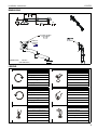
DIMENSIONS
LEGEND
INTERFACE
ROTATION
RANGE
90
MOUNTING PATTERN
COMPATIBILITY
100 X 100
75 X 75
0.81
20.6
UP
15
DOWN
DIMENSIONS: INCHES
[MILLIMETERS]
Tighten Fastener
Apretar elemento de fijación
Befestigungsteil festziehen
Apertar fixador
Serrare il fissaggio
Bevestiging vastdraaien
Serrez les fixations
Loosen Fastener
Aflojar elemento de fijación
Befestigungsteil lösen
Desapertar fixador
Allentare il fissaggio
Bevestiging losdraaien
Desserrez les fixations
Phillips Screwdriver
Destornillador Phillips
Kreuzschlitzschraubendreher
Chave de fendas Phillips
Cacciavite a stella
Kruiskopschroevendraaier
Tournevis à pointe cruciforme
Open-Ended Wrench
Llave de boca
Gabelschlüssel
Chave de bocas
Chiave a punte aperte
Steeksleutel
Clé à fourche
By Hand
A mano
Von Hand
Com a mão
A mano
Met de hand
À la main
Hex-Head Wrench
Llave de cabeza hexagonal
Sechskantschlüssel
Chave de cabeça sextavada
Chiave esagonale
Zeskantsleutel
Clé à tête hexagonale

KRA228 Installation Instructions
4
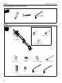
TOOLS REQUIRED FOR INSTALLATION
PARTS
#2
1/2" 1/8" (included)
3/16" (included)
A (1)
[Single monitor arm]
B (4)
M4 x 14mm C (4)
M4 x 25mm
D (4)
M10 x M5.3 x M10
Display Mounting Hardware
E (1)
[Plastic washer]
F (1)
[Pivot point G (4)*
spacer] [Stainless steel washer] H (2)
5/16-18” x 3 1/8”
J (1)
[Pivot pin]
K (1)
5/16" L (1)
1/8" M (1)
3/16"
*2 of 4 are extra in case washers in existing arm are lost or damaged

Installation Instructions KRA228
5
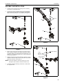
ASSEMBLY AND INSTALLATION
1. Carefully remove display from existing mount, following
instructions included with mount.
2. Loosen lock nut and 3" button head cap screw located in
arm to remove arm from mount. SAVE ALL HARDWARE
AND MOUNT ARM EXCEPT 3" SCREW! (See Figure 1)
Figure 1
3. Attach single monitor arm assembly (A) to original mount
base using one 5/16-18 x 3 1/8” button head cap screw (H),
one plastic washer (E), two stainless steel washers (G), one
pivot pin (J), one pivot point spacer (F), and one 5/16” lock
nut (K). (See Figure 2)
4. Reattach original mount arm (removed in Step 2) re-using
hardware removed in Step 2 and one 5/16-18 x 3 1/8” button
head cap screw (H). (See Figure 3)
NOTE: If two steel washers removed in Step 2 are lost or
damaged, replace with the extra two washers (G).
5. Complete installation following instructions included with
the original mount.
Figure 2
Figure 3
x 1
2
2
x 1
(discard)
(A)
3
(K) x 1
(H) x 1
3
(G) x 2
(E)
(J)
(F)
4
4
x 1
(H) x 1
(A)
Plastic washer
(Arm removed
in Step 2)
steel
washers
or (G) x 2

KRA228 Installation Instructions
6
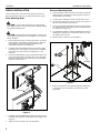
DISPLAY INSTALLATION
The mounting holes on the back of the display will either be
flush with the back surface or recessed into the back surface.
Flush Mounting Holes
CAUTION: Using screws of improper size may damage
your display! Proper screws will easily and completely thread
into display mounting holes.
CAUTION: Inadequate thread engagement in display may
cause display to fall! Back out screws ONLY as necessary to
allow installation!
1. Ensure faceplate is able to swivel and tilt easily, yet still be
tight enough to hold display in desired position. Adjust as
required before proceeding following original mount
installation instructions. (See Figure 4)
2. Carefully install two M4x14mm screws (B) into the upper
mounting holes on the display. Thread screws completely
into display, then back out three complete turns. (See
Figure 4)
3. Pick up and align display so that screws (B) (installed in the
previous step) fit into the mounting holes on the faceplate.
Rotate the faceplate as required. Lower the display firmly
into place. (See Figure 4)
Figure 4
4. Install two remaining M4x14mm Phillips screws (B) through
the lower mounting holes in faceplate into the display. (See
Figure 4)
5. Tighten all four screws (B). Do not overtighten!
Recessed Mounting Holes
1. Ensure faceplate is able to swivel and tilt easily, yet still be
tight enough to hold display in desired position. Adjust as
required before proceeding.
2. Carefully place display face down on protective surface.
3. Place the four spacers (D) over each of the mount holes on
the back of the display. (See Figure 5)
4. Pick up and orient the KRA228 so that the mounting holes
are aligned with the holes in the spacers; rotate the bracket
as required. (See Figure 5)
5. Using Phillips screwdriver, install four M4x25mm screws (C)
through the mounting holes, through the spacers and into
the display. (See Figure 5)
6. Tighten all four screws. Do not overtighten!
Figure 5
7. Refer to Adjustments and Cable Management information
in the original mount installation instructions for further
information.
2
4
3
KRA228
(D) x 4
5
(C) x 4
3
KRA228

Installation Instructions KRA228
7

KRA228 Installation Instructions
USA/International A 6436 City West Parkway, Eden Prairie, MN 55344
P800.582.6480 / 952.225.6000
F877.894.6918 / 952.894.6918
Europe A Franklinstraat 14, 6003 DK Weert, Netherlands
P+31 (0) 495 580 852
F+31 (0) 495 580 845
Asia Pacific A Office No. 918 on 9/F, Shatin Galleria
18-24 Shan Mei Street
Fotan, Shatin, Hong Kong
P852 2145 4099
F852 2145 4477
Chief, a products division of
Milestone AV Technologies
8800-002661 Rev01
2015 Milestone AV Technologies
www.chiefmfg.com
10/15
-
 1
1
-
 2
2
-
 3
3
-
 4
4
-
 5
5
-
 6
6
-
 7
7
-
 8
8


Chief KRA228B Le manuel du propriétaire
- Catégorie
- Mur
- Taper
- Le manuel du propriétaire
- Ce manuel convient également à
dans d''autres langues
- English: Chief KRA228B Owner's manual
Documents connexes
-
Chief KRA227SXRH Manuel utilisateur
-
-
-
-
-
Chief Manufacturing TA410 Manuel utilisateur
-
-
-
-