
Installation and Operation Instructions
Superior™ DRT2000 and DRC2000
Direct-Vent Gas Fireplaces
P/N 900004-00 Rev. G 04/2015
Ce manuel est disponible en francais, simplement
en faire la demande. Numéro de la pièce 900004-02.
PFS
®
USC
Models
DRT2033xxx *
DRC2033xxx *
DRT2035xxx *
DRC2035xxx *
DRT2040xxx *
DRC2040xxx *
DRT2045xxx *
DRC2045xxx *
P900004-00
* “xxx” indicates unique model identifiers. This manual covers all Superior™
DRT2000 and DRC2000 models.
INSTALLER: Leave this manual with the appliance.
CONSUMER: Retain this manual for future reference.
Installateur : Laissez cette notice avec l’appareil.
Consommateur : Conservez cette notice pour consultation ultérieure.
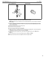
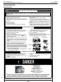
A barrier designed to reduce the risk of burns
from the hot viewing glass is provided with
this appliance and shall be installed for
the protection of children and other at-risk
individuals.
L’écran pare-étincelles fourni avec ce foyer réduit le
risque de brûlure en cas de contact accidentel avec la
vitre chaude et doit être installé pour la protection Des
enfants et Des personnes à risques.
This appliance may be installed in an aftermarket permanently located, manufactured home (USA only) or mobile
home, where not prohibited by local codes. This appliance is only for use with the type of gas indicated on the
rating plate. This appliance is not convertible for use with other gases, unless a certified kit is used.
Cet appareil peut installé dans une maison préfabriquée (mobile) déjà installée à demeure, si les réglements
locaux le permettent. Ce appareil doit être utilisé uniquement avec le type de gaz indiqué sure la plaque
signalétique. Cet appareil ne peut être converti à d’autres gaz, sauf si une trousse de conversion est utilsée.
— Do not store or use gasoline or other flammable
vapors and liquids in the vicinity of this or any other
appliance.
— WHAT TO DO IF YOU SMELL GAS
• Do not try to light any appliance.
• Do not touch any electrical switch; do not use any
phone in your building.
• Leave the building immediately.
• Immediately call your gas supplier from a neigh-
bor’s phone. Follow the gas supplier’s instructions.
• If you cannot reach your gas supplier, call the fire
department.
— Installation and service must be performed by a
qualified installer, service agency or the gas sup-
plier.
WARNING:
FIRE OR EXPLOSION HAZARD
Failure to follow safety warnings exactly could result
in serious injury, death, or property damage.
AVERTISSEMENT:
RISQUED’INDENDIE OU D’EXPLOSION
Le non-respect Des avertissements de sécurité
pourrait d’entraîner des blessures graves, la mort
ou des dommages matériels.
— Ne pas entreposer ni utilizer d’essence ni d’autres
vapeurs ou liquides inflammables dans le voisin-
age de cet appareil ou de tout autre appareil.
— QUE FAIRE SI VOUS SENTEZ UNE ODEUR DE GAZ:
• Ne pas tenter d’allumer d’appareil.
• Ne touchez à aucan interrupteur. Ne pas vous
servir des téléphones se trouvant dans le bâti-
ment où vous trouvez.
• Sortez immédiatement de bâtiment.
• Appelez immédiatement votre fournisseur de
gaz depuis un voisin. Suivez les instructions du
fournisseur.
• Si vous ne pouvez rejoindre le fournisseur de
gaz, appelez le service des incindies.
— L’installation et l’entretien doivent être assurés par
un installateur ou un service d’entretien qualifié
ou par le fournisseur de gaz.
Report No. F13-094

General Information
900004-00, 04/2015
Innovative Hearth Products
Superior™ DRT2000 and DRC2000 Direct-Vent Gas Fireplaces
2
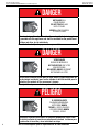
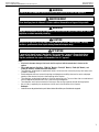
DANGER
HOT GLASS WILL
CAUSE BURNS.
DO NOT TOUCH GLASS
UNTIL COOLED.
NEVER ALLOW CHILDREN
TO TOUCH GLASS.
A barrier designed to reduce the risk of burns from the hot viewing glass
is provided with this appliance and shall be installed for the protection of
children and other at-risk individuals.
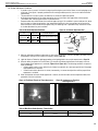
See attached color flyer for proper color representation
DANGER
VITRE CHAUDE
RISQUE DE BRÛLURES.
NE TOUCHEZ PAS UNE VITRE
NON REFROIDIE.
NE LAISSEZ JAMAIS UN ENFANT
DE TOUCHER LA VITRE.
L’écran pare-étincelles fourni avec ce foyer réduit le risque de brûlure en
cas de contact accidentel avec la vitre chaude et doit être installé pour la
protection Des enfants et Des personnes à risques.
Voir ci-joint tract pour une bonne représentation de la couleur
PELIGRO
EL VIDRIO CALIENTE
CAUSARÁ QUEMADURAS.
USTED DEBE NUNCA
TOCAR EL VIDRIO CALIENTE.
LOS NIÑOS DEBEN NUNCA
TOCAR EL VIDRIO.
Una barrera diseñada para reducir el riesgo de quemaduras desde la mir-
illa (vidrio) caliente es proveida con este aparato y deberá instalarse para
la protección de los niños y otros individuos en riesgo.
Vea el volante adjunto para la representación de color adecuado

General Information
900004-00, 04/2015
Innovative Hearth Products
Superior™ DRT2000 and DRC2000 Direct-Vent Gas Fireplaces
3
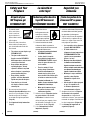
Afin d'éviter de vous
brûler gravement ou de
vous blesser, installez
une grille ou une barrière
physique pour empêcher
tout contact direct avec la vitre.
Suivez les instructions de sécurité
ci-dessous et veillez à ce que tous les
membres de votre famille soient conscients
du danger de brûlure encouru :
• Les surfaces de votre foyer deviennent
EXTRÊMEMENT CHAUDES !
• La vitre située à l'avant du
foyer atteint des températures
EXTRÊMEMENT ÉLEVÉES et peut
causer de graves blessures en
cas de contact.
• Tenez les enfants à l'écart
du foyer lorsqu'il fonctionne.
Surveillez attentivement les
enfants dans les pièces où un
foyer est utilisé afin d'éviter qu'ils
ne soient en contact avec la vitre.
• Tenez tous les vêtements, les
meubles, l'essence et tout autre liquide
inflammable à l'écart du foyer.
• Même après fermeture du gaz,
les surfaces du foyer restent
extrêmement chaudes.
Veillez à coller les Étiquettes de mise
en garde relatives à la sécurité
d'utilisation à l'endroit où vous
utilisez le foyer, pour rappeler à tous
les utilisateurs les dangers liés aux
températures élevées (Page 43).
Lisez L’information de sûreté
importante (Page 43).
Instale una malla o barrera física para evitar
el contacto directo con el vidrio y prevenir
las quemaduras y lesiones graves.
Siga las instrucciones de seguridad
a continuación y asegúrese de que
todos en su hogar sepan acerca de
este peligro de quemadura:
• ¡Las superficies de la chimenea
se ponen MUY CALIENTES!
• El vidrio delante de la
chimenea alcanza temperaturas
EXTREMADAMENTE ALTAS
y puede causar quemaduras
graves si se toca.
• Mantenga a los niños alejados de
la chimenea en funcionamiento.
Supervise en forma cercana a los
niños en cualquier cuarto donde haya
una chimenea funcionando para
impedir el contacto con el vidrio.
• Mantenga la ropa, mobiliario,
gasolina y otros líquidos
inflamables alejados de la
chimenea.
• Aún después de haber apagado
el gas, las superficies de
la chimenea permanecen
extremadamente calientes.
Asegúrese de colocar las Etiquetas
de advertencia de seguridad
de operación en el lugar donde
enciende la chimenea, para que todos
recuerden los peligros asociados con
las altas temperaturas (Página 43).
Lea Información importante de
seguridad (Página 5).
Seguridad y su
chimenea
La sécurité et
votre foyer
[FRENCH][ENGLISH]
[SPANISH]
Safety and Your
Fireplace
To prevent severe
burns and injuries,
install a screen or
physical barrier to
prevent direct contact
with the glass.
Follow the safety instructions
below and be sure everyone in
your household understands this
burn hazard:
• The surfaces on your fireplace get
EXTREMELY HOT!
• The glass on the front of the
fireplace reaches EXTREMELY
HIGH temperatures and can cause
severe burns if touched.
• Keep children away from an
operating fireplace. Closely
supervise children in any room
where a fireplace is operating to
prevent contact with glass.
• Keep clothing, furniture,
gasoline, and other flammable
liquids away from the fireplace.
• Even after the gas is turned
off, fireplace surfaces remain
extremely hot.
Be sure to attach the enclosed
Safety-in-Operation Warnings where
you turn on your fireplace, to help
remind everyone of the dangers
associated with high temperatures
(Page 43).
Read Important Safety Information
(Page 5)
All parts of your
IHP fireplace get
EXTREMELY HOT!
Toutes les parties de votre
foyer IHP deviennent
EXTRÊMEMENT CHAUDES !
¡Todas las partes de la
chimenea IHP se ponen
MUY CALIENTES!

General Information
900004-00, 04/2015
Innovative Hearth Products
Superior™ DRT2000 and DRC2000 Direct-Vent Gas Fireplaces
4
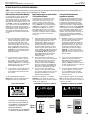
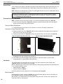
Traditional Fireplace Contemporary Fireplace
THANK YOU FOR YOUR PURCHASE. WE APPRECIATE YOUR BUSINESS!
Please carefully read and follow all instructions in this manual. Pay special attention to all warnings and safety
information. Following these safety, care, and operation instructions will help ensure many years of dependable and
enjoyable service from your fireplace.
Please read and understand these instructions before installing,
operating, or servicing this product.
We recommend that our
gas hearth products be
installed and serviced by
professionals who are
certied in the U.S. by the
National Fireplace Institute®
(NFI) as NFI Gas Specialists.
General Information
Important Safety Information ............................................................5
Fireplace Installation, Operation, and Maintenance Notices ............... 6
Packaging .......................................................................................... 8
Introduction ....................................................................................... 8
Installation
Requirements for the Commonwealth of Massachusetts ................10
Cold Climate Insulation ....................................................................10
Manufactured Home Requirements .................................................11
Location ...........................................................................................11
Vent Termination Clearances ...........................................................12
Minimum Clearances to Combustibles ............................................14
Wall Finishes / Surrounds / Mantels ................................................15
Installation Preparation ....................................................................15
Installation Sequence ......................................................................16
Construct the Fireplace Framing ......................................................16
Route the Gas Supply Line to the Fireplace .....................................18
Install the Vent System .................................................................... 24
Complete the Field Wiring ................................................................36
Install the [Optional] Blower Kit after Installation in the Framing .....38
Connect the Gas Line .......................................................................38
Verify Proper Fireplace Operation ....................................................39
Optional: Install the Firebox Liners ..................................................40
Contemporary Fireplaces: Install the Glass Media ...........................40
Traditional Fireplaces: Install the Logs, Volcanic Stone,
and Glowing Embers .......................................................................40
Install the Glass Door ......................................................................40
Adjust the Air Shutter to Ensure Proper Flame Appearance ............. 40
Install the Hood ...............................................................................42
Install the Finishing Materials ..........................................................42
Attach the Safety-in-Operation Warnings.........................................43
Installation Accessories ................................................................... 44
Gas Conversion Kits ........................................................................46
Operation
Maintenance ....................................................................................59
Accessory Components ...................................................................63
Lighting Instructions .......................................................................66
Troubleshooting ...............................................................................70
Replacement Parts ..........................................................................72
Warranty .......................................................................................... 75

General Information
900004-00, 04/2015
Innovative Hearth Products
Superior™ DRT2000 and DRC2000 Direct-Vent Gas Fireplaces
5
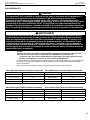
GENERAL INFORMATION
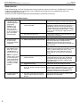
IMPORTANT SAFETY INFORMATION L’information de sûreté importante Información importante de seguridad
WARNING AVERTISSEMENT ADVERTENCIA
Do not operate appliance with the
glass front removed, cracked or
broken.
Ne pas utiliser l’appareil si le
panneau frontal en verre n’est pas
en place, est craqué ou brisé.
No opere el artefacto con el frente
de vidrio quitado, agrietado o roto.
Do not use this fireplace if any part has
been under water. Immediately call a
qualified service technician to inspect the
fireplace and to replace any part of the
control system and any gas control which
has been under water.
Ne pas utiliser cet appareil s’il a été
plongé, même partiellement, dans l’eau.
Appeler un technicien qualifié pour
inspecter l’appareil et remplacer toute
partie du système de commande et toute
commande qui a été plongée dans l’eau.
No use este artefacto si alguna de sus
partes ha estado bajo agua. Llame
de inmediato a un técnico de servicio
calificado para que inspeccione el
artefacto y reemplace cualquier parte del
sistema de control y cualquier control de
gas que haya estado bajo agua.
Due to high temperatures, the fireplace
should be located out of traffic and away
from furniture and draperies.
En raison des températures élevées,
l’appareil devrait être installé dans un
endroit où il y a peu de circulation et loin
du mobilier et des tentures.
Debido a las altas temperaturas, el
artefacto debe situarse fuera de las
áreas de tráfico y lejos del mobiliario y
cortinas.
Children and adults should be alerted to
the hazards of high surface temperature
and should stay away to avoid burns or
clothing ignition.
Les enfants et les adultes devraient être
informés des dangers que posent les
températures de surface élevées et se
tenir à distance afin d’éviter des brûlures
ou que leurs vêtements ne s’enflamment.
Se debe alertar a los niños y adultos
sobre los peligros de las altas
temperaturas en la superficie y que
se mantengan alejados para evitar
quemaduras o ignición de la ropa.
Clothing or other flammable material
should not be placed on or near the
fireplace.
On ne devrait pas placer de vêtements
ni d’autres matières inflammables sur
l’appareil ni à proximité.
No debe colocarse ropa u otros
materiales inflamables sobre y cerca del
artefacto.
Young children should be carefully
supervised when they are in the same
room as the fireplace. Toddlers, young
children, and others may be susceptible
to accidental contact burns. A physical
barrier is recommended if there are
at-risk individuals in the house. To
restrict access to a fireplace or stove,
install an adjustable safety gate to keep
toddlers, young children, and other at-
risk individuals out of the room and away
from hot surfaces.
Les jeunes enfants devraient être
surveillés étroitement lorsqu’ils se
trouvent dans la même pièce que
l’appareil. Les tout petits, les jeunes
enfants ou les adultes peuvent subir des
brûlures s’ils viennent en contact avec
la surface chaude. Il est recommandé
d’installer une barrière physique si des
personnes à risques habitent la maison.
Pour empêcher l’accès à un foyer ou à un
poêle, installez une barrière de sécurité
; cette mesure empêchera les tout petits,
les jeunes enfants et toute autre personne
à risque d’avoir accès à la pièce et aux
surfaces chaudes.
Se debe supervisar de cerca a los niños
cuando estén en el mismo cuarto que
el artefacto. Los niños pequeños, los
jóvenes y otras personas pueden ser
susceptibles a quemaduras por contacto
accidental. Se recomienda instalar
una barrera física si hay personas en
riesgo en la casa. Para restringir el
acceso a una chimenea o estufa, instale
una puerta de seguridad ajustable
para mantener a los niños pequeños,
jóvenes y otras personas en riesgo fuera
del cuarto y lejos de las superficies
calientes.
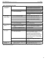
Any safety screen or guard removed for
servicing a fireplace must be replaced
prior to operating the fireplace.
Tout écran ou protecteur retiré pour
permettre l’entretien de l’appareil doit
être remis en place avant de mettre
l’appareil en marche.
Cualquier malla o resguardo de seguridad
quitado para dar servicio a un artefacto,
debe reinstalarse antes de operar
el artefacto.
Installation and repair should be done
by a qualified service person. The
fireplace should be inspected before use
and at least annually by a professional
service person. More frequent cleaning
may be required due to excessive lint
from carpeting, bedding material, et
cetera. It is imperative that control
compartments, burners, and circulating
air passageways of the fireplace be kept
clean (Maintenance on Page 59).
L’installation et la réparation devrait
être confiées à un technicien qualifié.
L’appareil devrait faire l’objet
d’une inspection par un technicien
professionnel avant d’être utilisé et au
moins une fois l’an par la suite. Des
nettoyages plus fréquents peuvent être
nécessaires si les tapis, la literie, et
cetera produisent une quantité importante
de poussière. Il est essentiel que les
compartiments abritant les commandes,
les brûleurs et les conduits de circulation
d’air de l’appareil soient tenus propres
(Page 59).
Una persona de servicio competente
debe realizar la instalación y reparación.
Una persona de servicio profesional
debe inspeccionar el artefacto antes
de usar al menos una vez por año. Se
puede requerir limpieza más frecuente
debido a la pelusa excesiva del
alfombrado, del material de cobijas,
etc. Es imprescindible mantener limpios
los compartimientos de control, los
quemadores y los pasajes de circulación
del aire del artefacto (Página 59).
[English] [French] [Spanish]

General Information
900004-00, 04/2015
Innovative Hearth Products
Superior™ DRT2000 and DRC2000 Direct-Vent Gas Fireplaces
6
FIREPLACE INSTALLATION, OPERATION, AND MAINTENANCE NOTICES
DO NOT ATTEMPT TO ALTER OR MODIFY THE CONSTRUCTION OF THE APPLIANCE OR ITS COMPONENTS. ANY
MODIFICATION OR ALTERATION MAY VOID THE WARRANTY, CERTIFICATION, AND LISTINGS OF THIS UNIT.
WARNING
Improper installation, adjustment, alteration, service or maintenance can cause injury or
property damage. Refer to this manual. For assistance or additional information consult a
qualified installer, service agency or the gas supplier.
AVERTISSEMENT
Une installation, un réglage,une modification, une réparation ou un entretien mal effectué
peut causer des dommages matériels ou des blessures. Voir la notice de l’utilisateur qui
accompagne l’appareil. Pour de l’aide ou des renseignements supplémentaires, consultez
un installateur, un technicien agréé ou le fournisseur de gaz.
WARNING
Failure to comply with these installation instructions will result in an improperly installed
and operating appliance, voiding its warranty. Any change to this appliance and/or its
operating controls is dangerous.

General Information
900004-00, 04/2015
Innovative Hearth Products
Superior™ DRT2000 and DRC2000 Direct-Vent Gas Fireplaces
7
WARNING
Clothing or other flammable material should not be placed on or near the appliance.
AVERTISSEMENT
On ne devrait pas placer de vêtements ni d’autres matières inflammables sur l’appareil ni à proximité.
WARNING
Improper installation or use of this appliance can cause serious injury or death from fire, burns,
explosion or carbon monoxide poisoning.
CAUTION
Hot while in operation. Do not touch. Severe Burns may result. Keep children, clothing
furniture, gasoline and other liquids having flammable vapors away.
ATTENTION
L’appareil est chaud lorsqu’il fonctionne. Ne pas toucher l’appareil. Risque de brûlures
graves. Surveiller les enfants. Garder les vêtements, les meubles, l’essence ou autres
liquides produisant des vapeur inflammables loin de l’appareil.
NOTE:
• If the barrier becomes damaged, the barrier shall be replaced with the manufacturer’s barrier for this
applian
• For use with barrier(s) Part No(s). F1902 (33” Models), F1839 (35” Models), F1840 (40” Models), and
F1903 (45” Models). Follow installation instructions.
• These fireplaces are designed as supplemental heaters, and are not to be used as the primary heat source when
installed in a dwelling.
• Provide adequate clearances around air openings and adequate accessibility clearance for service and proper
operation. Never obstruct the front or back openings of the fireplace.
• These fireplaces are designed to operate on natural or propane gas only. The use of other fuels or combination of
fuels will degrade the performance of this system and may be dangerous.
• These fireplaces must not be connected to a chimney or flue serving a separate solid fuel burning fireplace.
• Only trim kit(s) supplied by the manufacturer shall be used in the installation of this fireplace.
Remarqué :
• Seules les trousses de garniture fournies par le fabricant doivent être utilisées pour l’installation de cet appareil.

General Information
900004-00, 04/2015
Innovative Hearth Products
Superior™ DRT2000 and DRC2000 Direct-Vent Gas Fireplaces
8
INSTALLATION
PACKAGING
All models include
The assembled vented gas fireplace heater is packaged with:
• Literature Kit (envelope in bottom compartment containing Installation and Operation Instructions (this manual),
and Safety-In-Operation Warning Labels)
• U-Shaped Vent Restrictor (attached to Literature Kit envelope)
• Hood (Inside firebox)
Traditional models also include
• Log Set (packaged in a carton inside the firebox)
• Volcanic Stone—1 bag (in bottom compartment)
• Glowing Embers—1 bag (in bottom compartment)
Contemporary models also include
• Glass Media
• Contemporary Burner Panel
INTRODUCTION
These vented gas fireplace heaters are sealed combustion, air-circulating gas fireplaces designed for residential and
commercial applications.
Millivolt fireplaces have a millivolt gas control valve with piezo ignition system. If a blower will be installed, electrical
power must be provided at the time of fireplace installation.
Electronic fireplaces are designed with an electronic intermittent pilot ignition system. External electrical power is
required to operate these units. In the event of a power outage, four (4) AA batteries (in battery holder) provide
backup power for fireplace operation (excluding the optional blower).
NOTE: Installation and repair should be done by a qualified service person. The fireplace should be inspected before
use and at least annually by a professional service person. More frequent cleaning may be required due to excessive
lint from carpeting, bedding material, etcetera. It is imperative that control compartments, burners and circulating air
passageways of the fireplace be kept clean.
Remarqué : L’installation et la réparation devrait être confiées à un technicien qualifié. L’appareil devrait faire
l’objet d’une inspection par un technicien professionnel avant d’être utilisé et au moins une fois l’an par la suite.
Des nettoyages plus fréquents peuvent être nécessaires si les tapis, la literie, et cetera produisent une quantité
importante de pous-sière. Il est essentiel que les compartiments abritant les commandes, les brûleurs et les
conduits de circulation d’air de l’appareil soient tenus propres.
NOTE: Diagrams and illustrations are not necessarily shown to scale.
Approved Vent Components
These fireplaces are designed, tested and listed for operation and installation with the following vent
components only:
• Secure Vent
®
Direct-Vent System Components,
• Secure Flex
®
Flexible Vent Components, and
• Z-FLEX
®
Model GA Venting Systems listed to UL1777 and ULCS635 manufactured by Flexmaster
Canada Limited.
Use only the correct size venting (4 1/2” inner and 7 1/2” outer).
These approved vent system components are labeled for identification. DO NOT use any other manufacturer’s vent
components with these fireplaces.
Codes and Standards
These fireplaces comply with National Safety Standards and are tested and listed by PFS Corporation
(Report No. F13-94) to ANSI Z21.88 (in Canada, CSA-2.33), and CAN/CGA-2.17-M91 in both USA and Canada, as
vented gas fireplace heaters.
These fireplaces are listed for installation in bedrooms and manufactured homes.
The installation must conform to local codes or, in the absence of local codes, with the National Fuel Gas Code, ANSI
Z223.1/NFPA 54—latest edition (In Canada, the current CAN/CGA-B149.1 installation code).
The fireplace, when installed, must be electrically grounded and wired in accordance with local codes or, in the
absence of local codes, with the National Electrical Code, ANSI/NFPA 70—latest edition, or the Canadian Electrical
Code, CSA C22.1—latest edition.

General Information
900004-00, 04/2015
Innovative Hearth Products
Superior™ DRT2000 and DRC2000 Direct-Vent Gas Fireplaces
9
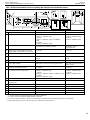
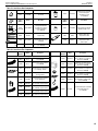
BTU Input
Table 1: Input Rate, Gas Valves
Models
Input Rate (BTU/HR)
Natural Gas Propane Gas
DRC2033 / DRT2033 12,000 10,000
DRC2035 / DRT2035 14,000 12,000
DRC2040 / DRT2040 16,000 15,000
DRC2045 / DRT2045 20,000 19,000
Table 2: Thermal Efficiency (%)
Model
Millivolt Electronic
AFUE * P4 ** AFUE * P4 **
DRC2033 / DRT2033 64 60.4 64 64.8
DRC2035 / DRT2035 65.5 61 65.5 65
DRC2040 / DRT2040 65.5 62 65.5 65
DRC2045 / DRT2045 65 63 65 66
* AFUE is a measurement of the US Department of Energy, ** P4 (EnerGuide) is a measurement of the Canadian Office of Energy Efficiency.
NOTE: Efficiiencies are based on the most commonly used F1797 termination.
Gas Pressure
Table 3: Inlet Gas Supply Pressure
Fuel Minimum Maximum
Natural Gas 5” WC / (1.25 kPa) 10.5” WC / (2.61 kPa)
Propane 11.0” WC / (2.74 kPa) 13.0” WC / (3.23 kPa)
Table 4: Manifold Gas Supply Pressure
Fuel Pressure
Natural Gas 3.5” WC / (0.87 kPa)
Propane 10.0” WC / (2.49 kPa)
Test gauge connections are provided on the front of the millivolt and electronic gas control valve (identified IN for the
inlet and OUT for the manifold side). The control valves have a 3/8” (10 mm) NPT thread inlet and outlet side of the
valve (Figure 1 and Figure 2).
Figure 1: Millivolt Gas Valve Figure 2: Electronic Gas Valve
Propane tanks are at pressures that will cause damage to valve components. Verify that the tanks have step down
regulators to reduce the pressure to safe levels.
The appliance and its appliance main gas valve must be disconnected from the gas supply piping system during
any pressure testing of that system at test pressures in excess of 1/2 psi (3.5 kPa).
The appliance must be isolated from the gas supply piping system by closing its equipment shutoff valve during
any pressure testing of the gas supply piping system at test pressures equal to or less than 1/2 psi (3.5 kPa).

Installation
900004-00, 04/2015
Innovative Hearth Products
Superior™ DRT2000 and DRC2000 Direct-Vent Gas Fireplaces
10
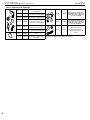
Orifice Sizes—Sea Level to High Altitude
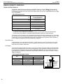
These fireplaces are tested and approved for installation at elevations of 0–4500 ft (0–1372 m) above sea level
using the standard burner orifice sizes (Table 5). For elevations above 4500 ft, contact your gas supplier or qualified
service technician.
Table 5: Burner Orifice Sizes, Elevation 0–4500 ft ( 0–1372 m)
Model
Natural Gas
drill size
Propane
drill size
DRC2033 / DRT2033 #51 (0.067”)* #61 (0.039”)*
DRC2035 / DRT2035 #49 (0.073”)* #58 (0.042”)*
DRC2040 / DRT2040 #48 (0.076”)* #56 (0.046”)*
DRC2045 / DRT2045 #44 (0.086”)* #55 (0.052”)*
* Standard size installed at factory
Deration
At elevations above 4500 ft, the amount of BTU fuel value delivered must be reduced by either:
• Using gas that has been derated by the gas company.
• Changing the burner orifice to a smaller size as regulated by the local authorities having jurisdiction and by the
(USA) National Fuel Gas Code NFPA 54/ANSI Z223.1—latest edition or, in Canada, the CAN/CGA-B149.1 codes—
latest edition.
NOTE: Flame breadth, height and width will diminish 4% for every 1,000 ft of altitude.
IN CANADA—CAN/CGA-2.17-M91 (HIGH ALTITUDE):
THE CONVERSION SHALL BE CARRIED OUT BY A MANUFACTURER’S AUTHORIZED REPRESENTATIVE,
IN ACCORDANCE WITH THE REQUIREMENTS OF THE MANUFACTURER, PROVINCIAL OR TERRITORIAL
AUTHORITIES HAVING JURISDICTION AND IN ACCORDANCE WITH THE REQUIREMENTS OF THE CAN/
CGA-B149.1 OR CAN/CGA-B149.2 INSTALLATION CODES.
REQUIREMENTS FOR THE COMMONWEALTH OF MASSACHUSETTS
These fireplaces are approved for installation in the U.S. state of Massachusetts if the following additional
requirements are met:
• Install this fireplace in accordance with Massachusetts Rules and Regulations 248 C.M.R..
• Installation and repair must be done by a plumber or gas fitter licensed in the Commonwealth of Massachusetts.
• The flexible gas line connector used shall not exceed 36” (914 mm) in length.
• The individual manual shutoff must be a T-handle type valve.
Massachusetts Horizontal Vent Requirements
In the Commonwealth of Massachusetts, horizontal terminations installed less than seven (7) ft above the finished
grade must comply with the following additional requirements:
• A hard wired carbon monoxide detector with an alarm and battery back-up must be installed on the floor level
where the gas fireplace is installed. The carbon monoxide detector must comply with NFPA 720, be ANSI/UL
2034 listed and be ISA certified.
• A metal or plastic identification plate must be permanently mounted to the exterior of the building at a minimum height
of eight (8) ft above grade and be directly in line with the horizontal termination. The sign must read, in print size no
less than one-half (1/2) inch in size, GAS VENT DIRECTLY BELOW. KEEP CLEAR OF ALL OBSTRUCTIONS.
COLD CLIMATE INSULATION
For cold climate installations, seal all cracks around your fireplace with noncombustible material and wherever cold
air could enter the room. It is especially important to insulate outside chase cavity between studs and under floor on
which fireplace rests, if floor is above ground level. Gas line holes and other openings should be caulked or stuffed
with unfaced fiberglass insulation.
NOTE: Do not use loose, or blown-in insulation in the cavity surrounding the fireplace.
If the fireplace is being installed on a cement slab in cold climates, a sheet of plywood or other raised platform can
be placed underneath to prevent conduction of cold transferring to the fireplace and into the room. It also helps to
seal inside surfaces and tape for maximum air tightness and caulk firestops.

Installation
900004-00, 04/2015
Innovative Hearth Products
Superior™ DRT2000 and DRC2000 Direct-Vent Gas Fireplaces
11
MANUFACTURED HOME REQUIREMENTS
This appliance may be installed in an aftermarket, permanently located, manufactured home (USA only) or mobile
home, where not prohibited by local codes.
Cet appareil peut être installé dans une maison préfabriquée (mobile) déjà installée à demeure si les règlements
locaux le permettent.
This appliance is only for use with the type of gas indicated on the rating plate. This appliance is not convertible for
use with other gases, unless a certified kit is used.
Cet appareil doit être utilisé uniquement avec le type de gaz indiqué sur la plaque signalétique. Cet appareil ne
peut être converti à d’autres gaz, sauf si une trousse de conversion est utilisée.
CAUTION
Ensure that the cross members are not cut or weakened during installation. The structural
integrity of the manufactured home floor, wall, and ceiling / roof must be maintained.
CAUTION
This appliance must be grounded to the chassis of the manufactured home in accordance
with local codes or in the absence of local codes, with the National Electrical Code ANSI /
NFPA 70—latest edition or the Canadian Electrical Code CSA C22.1—latest edition.
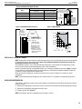
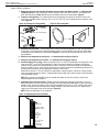
LOCATION
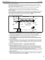
In selecting the location, the aesthetic and functional use of the fireplace are primary concerns. However, vent
system routing to the exterior and access to the fuel supply are also important.
Due to high temperatures, the fireplace should be located out of traffic and away from furniture and draperies.
En raison des températures élevées, l’appareil devrait être installé dans un endroit où il y a peu de
circulation et loin du mobilier et des tentures.
The location should also be free of electrical, plumbing or other heating/air conditioning ducting.
These direct-vent fireplaces are uniquely suited for installations requiring a utility shelf positioned directly above the
fireplace. Utility shelves like these are commonly used for locating television sets and decorative plants.
Be aware that this is a heat producing fireplace. Objects placed above the unit are exposed to elevated temperatures.
Do not insulate the space between the fireplace and the area above it.
The minimum height from the base of the fireplace to the underside of combustible materials used to construct a
utility shelf in this fashion is shown in Table 9 and Table 10.
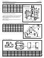
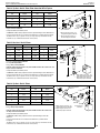
Figure 3: Typical Locations and Venting
Vertical Vent
(Rear Vent)
HORIZONTAL VENT
(Rear Vent Application with a chase)
HORIZONTAL VENT
(Top Vent Application)
VERTICAL VENT
(Top Vent Application)
(Rear Vent Application)
VERTICAL VENT
(Rear Vent Application without a chase)
HORIZONTAL VENT
HORIZONTAL VENT
(Rear Vent Application with a chase)
HORIZONTAL VENT
(Top Vent Application)
VERTICAL VENT
(Top Vent Application)
(Rear Vent Application)
VERTICAL VENT
(Rear Vent Application without a chase)
HORIZONTAL VENT
Horizontal Vent
(Top Vent)
Vertical Vent
(Top Vent)
HORIZONTAL VENT
(Rear Vent Application with a chase)
HORIZONTAL VENT
(Top Vent Application)
VERTICAL VENT
(Top Vent Application)
(Rear Vent Application)
VERTICAL VENT
(Rear Vent Application without a chase)
HORIZONTAL VENT
HORIZONTAL VENT
(Rear Vent Application with a chase)
HORIZONTAL VENT
(Top Vent Application)
VERTICAL VENT
(Top Vent Application)
(Rear Vent Application)
VERTICAL VENT
(Rear Vent Application without a chase)
HORIZONTAL VENT
Horizontal Vent
(Rear Vent with chase)
HORIZONTAL VENT
(Rear Vent Application with a chase)
HORIZONTAL VENT
(Top Vent Application)
VERTICAL VENT
(Top Vent Application)
(Rear Vent Application)
VERTICAL VENT
(Rear Vent Application without a chase)
HORIZONTAL VENT
Horizontal Vent
(Rear Vent without chase)
Top Vent
Top Vent
Top Vent
Top Vent Top Vent
Top Vent
Rear Vent
Rear Vent
Recessed
Installation

Installation
900004-00, 04/2015
Innovative Hearth Products
Superior™ DRT2000 and DRC2000 Direct-Vent Gas Fireplaces
12
VENT TERMINATION CLEARANCES
These instructions should be used as a guideline and do not supersede local codes in any way. Install venting
according to local codes, these instructions, the current National Fuel Gas Code (ANSI Z223.1/NFPA 54) in the USA or
the current standards of CAN/CGA-B149.1 in Canada.
Vertical Vent Termination Clearances
Terminate multiple vent terminations according to the installation codes listed above and Figure 4.
Figure 4: Multiple Terminations
12”
(305 mm)
minimum
Terminate single vent caps relative to building components according to Table 6 and Figure 4.
Table 6: Termination Heights for Vents above Flat or Sloped Roofs (NFPA 54 / ANSI Z223.1)—Gas Vent Rule
Roof Pitch Termination Height *
12
X
Roof pitch is X/12
2 ft
minimum
2 ft minimum
Lowest
discharge
opening
H*
*H = minimum height from roof to
lowest discharge opening of vent
Horizontal overhang
Vertical
wall
Vent
termination
Storm collar
Concentric
vent pipe
Flashing
1” (25.4 mm) minimum
clearance to combustibles
Flat to 6/12 1.0 ft (0.3 m)
6/12 to 7/12 1.25 ft (0.38 m)
7/12 to 8/12 1.5 ft (0.46 m)
8/12 to 9/12 2.0 ft (0.61 m)
9/12 to 10/12 2.5 ft (0.76 m)
10/12 to 11/12 3.25 ft (0.99 m)
11/12 to 12/12 4.0 ft (1.22 m)
12/12 to 14/12 5.0 ft (1.52 m)
14/12 to 16/12 6.0 ft (1.83 m)
16/12 to 18/12 7.0 ft (2.13 m)
18/12 to 20/12 7.5 ft (2.29 m)
20/12 to 21/12 8.0 ft (2.44 m)
Horizontal Vent Termination Clearances
The horizontal vent termination must have a minimum of 6” (152 mm) clearance to any overhead combustible
projection of 2 1/2” (64 mm) or less (Figure 5). For projections exceeding 2 1/2” (64 mm) (Figure 5). For additional
vent location restrictions refer to Table 7.
All horizontal terminations may be located as close as 6” (152mm) to any (non-combustible and combustible)
exterior sidewall. This distance may be decreased to 2” (51mm) for noncombustible exterior sidewalls with all
approved terminations (Table 21).
Figure 5: Horizontal Vent Termination Clearances
NOTE: See Figure 27 on
Page 31 for exterior
wall recess allowances
for compact horizontal
termination.
Combustible projection
2 1/2” or less in length
Combustible projection
greater than 2 1/2” in length
6
(152)
Termination kit*
Termination kit
6”
6”
(153 mm)
Ventilated
soffit - 18”
(457 mm)
Unventilated
soffit - 12”
(305 mm)
*4” to center of termination for F1797, 8” for 94L10, and 10” for H1968
*
Use 6.5” for
all horzontal
terminations
applicable

Installation
900004-00, 04/2015
Innovative Hearth Products
Superior™ DRT2000 and DRC2000 Direct-Vent Gas Fireplaces
13
Table 7: Horizontal vent termination clearances for buildings with combustible and noncumbustible exteriors
Fixed
Closed
Openable
Fixed
Closed
V
V
V
V
V
V
X
X
V
X
G
G
J
F
B
B
K
H
I
A
E
L
D
B
M
C
B
V
V
A
G
G
B
TERMINATION CAP
AIR SUPPLY INLET
GAS METER RESTRICTED AREA
(TERMINATION PROHIBITED)
Openable
See Table 6
V
V
Inside Corner
V
V
Outside Corner Recessed Location
Balcony with No Side
Wall
V
Balcony with Perpendicular Side Wall
G
F
M
M
N
P
O
Q
U.S. Installation ** Canadian Installation *
A Clearance above grade, veranda, porch, desk, or balcony 12” (300 mm) ** 12” (300 mm) *
B Clearance to window or door that may be opened 6” (150 mm)
for fireplaces < 10,000 Btu/h (3 kW),
9” (230 mm)
for fireplaces > 10,000 Btu/h (3 kW), and < 50,000 Btu/h
(15 kW),
12” (300 mm)
for fireplaces > 50,000 Btu/h (15 kW) **
6” (150 mm)
for fireplaces < 10,000 Btu/h (3 kW),
12” (300 mm)
for fireplaces > 10,000 Btu/h (3 kW)
C Clearance to permanently closed window 9” (229 mm)
recommended to prevent window condensation
12” (305 mm)
recommended to prevent
window condensation
D Vertical clearance to ventilated soffit located above the
termination within a horizontal distance of 18” (458 mm)
18” (458 mm) 18” (458 mm)
E Clearance to unventilated soffit 12” (305 mm) 12” (305 mm)
F Clearance to outside corner 5” (127 mm)
minimum
5” (127 mm)
minimum
G Clearance to inside corner 6” (152 mm) minimum 6” (152 mm) minimum
H Clearance to each inside of center line extended above
meter / regulator assembly
36” (910 mm)
within a height of 15 ft above the meter / regulator assembly **
36” (910 mm)
within a height of 15 ft above the meter /
regulator assembly *
I Clearance to service regulator vent outlet 36” (910 mm)** 36” (910 mm)*
J Clearance to nonmechanical air supply inlet to building or
the combustion air inlet to any other fireplace
6” (150 mm)
for fireplaces < 10,000 Btu/h (3 kW),
9” (230 mm)
for fireplaces > 10,000 Btu/h (3 kW) and < 50,000 Btu/h (15 kW),
12” (300 mm)
for fireplaces > 50,000 Btu/h (15 kW)**
6” (150 mm)
for fireplaces < 10,000 Btu/h (3 kW),
12” (300 mm)
for fireplaces > 10,000 Btu/h (3 kW)
K Clearance to a mechanical air supply inlet 36” (910 mm) above if within 10 ft (3 m) horizontally ** 72” (1830 mm) *
L Clearance above paved sidewalk or paved diveway located
on public property
84” (2130 mm) ‡ 84” (2130 mm) ‡
M Clearance under veranda, porch, deck or balcony 12” (300 mm) *‡ 12” (300 mm) *‡
N Depth of alcove (maximum) 72” (1830 mm) ** 72” (1830 mm) *
O Clearance to termination (alcove) 6” (15.2 mm) ** 6” (15.2 mm)*
P Width of alcove (minimum) 36” (910 mm) ** 36” (910 mm) *
Q Clearance to combustible above (alcove) 18” (457 mm) ** 18” (457 mm) *
*
**
‡
*‡
In accordance with the current CSA-B149.1 National Gas And Propane Installation Code
In accordance with the curent ANSI Z223.1/NFPA 54 National Fuel Gas Codes
A vent shall not terminate directly above a sidewalk or paved driveway which is located between two single family dwellings and serves both dwellings
Only permitted if veranda, porch, deck, or balcony is fully-open on a minimum two sides beneath the floor

Installation
900004-00, 04/2015
Innovative Hearth Products
Superior™ DRT2000 and DRC2000 Direct-Vent Gas Fireplaces
14
MINIMUM CLEARANCES TO COMBUSTIBLES
Fireplace And Vent Clearances
The fireplace is approved with zero clearance to combustible materials on all sides (Table 8), with the following
exception: The unit may not be recessed (allowance made for mantel legs / side trim in Figure 6). When the unit is
installed with one side flush with a wall, the wall on the other side of the unit must not extend beyond the front edge
of the unit (Figure 6).
Table 8: Minimum Clearances *
Back
1” (26mm) to wrapper for 45” model, all
others 1/2” (13mm) to wrapper
0” (0 mm) to Spacers
Sides
1/2” (13 mm) to wrapper
0” (0 mm) to Spacers **
Top Standoffs 0” (0 mm) to top standoffs
Floor 0” (0 mm)
From Bottom of Unit to Ceiling 64” (1626 mm)
Vent
3” (76 mm)—Top * ***
1” (25.4 mm)—Sides and Bottom
Front Service Clearance—
clearance immediately in front of viewing area(s)
36” (914 mm)
* 3” (76 mm) above any horizontal/inclined vent component.
** See Page 19 for clearance requirements to the nailing flange located at each side of the unit and any screw heads adjacent to it.
*** Top vent clearance can be reduced to 2” on horizontal runs when first elbow is located at least 6 ft above the fireplace.
The fireplace must be mounted on a fully supported base extending the full width and depth of the unit. The fireplace
may be located on or near conventional construction materials. However, if installed on combustible materials, such
as carpeting, vinyl tile or other combustible material other than wood flooring, the appliance shall be installed on a
metal or wood panel extending the full width and depth of the appliance.
Hearth Extension
A hearth extension is not required with this fireplace. If a hearth extension is used, do not block the lower control
compartment door. Any hearth extension used is for appearance only and does not have to conform to standard
hearth extension installation requirements.
Shelf Height
To provide for the lowest possible shelf surface, use the rear vent model. For top vent models, the venting attached
to the top vent should be routed in a way to minimize obstructions to the space above the fireplace. Do not insulate
the space between the fireplace and the area above it (Table 9 and Table 10). The minimum height from the base
of the fireplace to the underside of combustible materials used to construct a utility shelf in this fashion is shown in
Table 9 and Table 10.
Table 9: Combustible Shelf Height—Top Vent
Model
Top Vent with one 90° Elbow
Shelf Height
(see table)
No combustibles
or insulation
in the shaded
area between
the appliance
and the shelf
above it.
Secure Vent
®
Secure Flex
®
(flex elbow)
DRC2033 / DRT2033 44” (1118 mm) 46” (1168 mm)
DRC2035 / DRT2035 47” (1194 mm) 49” (1245 mm)
DRC2040 / DRT2040 52” (1321 mm) 54” (1372 mm)
DRC2045 / DRT2045 50” (1270 mm) 52” (1321 mm)

Installation
900004-00, 04/2015
Innovative Hearth Products
Superior™ DRT2000 and DRC2000 Direct-Vent Gas Fireplaces
15
Table 10: Combustible Shelf Height—Rear Vent
Model
Rear Vent with two 90° Elbows
Shelf Height
(see table)
No
combustibles
or insulation
in the shaded
area between
the appliance
and the shelf
above it.
≥3” clearance from shelf to
top of fireplace and/or vent
pipe, whichever is higher
Secure Vent
®
Secure Flex
®
(flex elbow)
DRC2033 / DRT2033 34” (864 mm) 34” (864 mm)
DRC2035 / DRT2035 35 1/2” (902 mm) 35 1/2” (902 mm)
DRC2040 / DRT2040 40 1/2” (1029 mm) 40 1/2” (1029 mm)
DRC2045 / DRT2045 45 1/2” (1156 mm) 45 1/2” (1156 mm)
Figure 6: Combustible Side Clearances Figure 7: Mantel Height
3 1/2 in.
(89 mm)
6 in.
(152 mm)
Top View of
Fireplace
45
o
Combustible
mantel legs may
project beyond either side
of the fireplace opening
as long as they are kept
within the shaded area
illustrated here.
Combustible Materials
Allowed In Shaded Area
“Safe Zone”
Combustible Walls
shown in dark gray
At 6 in. minimu
m
side wall clearance,
a combustible wal
l
can project to an
y
length
.
Top View of
Fireplace
45
o
6”
(152 mm)
Combustible materials
allowed in shaded area
“Safe Zone”.
Combustible walls
shown in dark gray
Combustible mantel
legs may project
beyond either side of
the fireplace opening
as long as they are kept
within the shaded area
illustrated here.
At 6” minimum
side wall
clearance, a
combustible
wall can project
to any length.
3 1/2”
(89 mm)
12
(305)
10
(254)
8
(203)
6
(152)
4
(102)
2
(51)
in. (mm)
8 (203)
10 (254)
12 (305)
14 (356)
16 (406)
18 (457)
Hood
Fireplace
Mantel depth
Wall Finishes / Surrounds / Mantels
NOTE: Combustible wall finish materials and/or surround materials must not be allowed to encroach the area defined
by the fireplace front face (black sheet metal). Never allow combustible materials to be positioned in front of or
overlapping the fireplace face (Figure 41).
Non-combustible materials, such as surrounds and other fireplace trim, may be installed on the fireplace face, but they
must not cover any portion of the removable glass panel or control compartment.
Vertical installation clearances to combustible mantels vary according to the depth of the mantel (Figure 7). Mantels
constructed of non-combustible materials may be installed at any height above the fireplace opening. However, do
not allow anything to hang below the fireplace hood.
Minimum clearance requirements include any projections such as shelves, window sills, mantels, etc. above
the fireplace.
NOTE: To avoid heat-related finish damage, use finish materials rated 175 °F, or higher, on the underside of the mantel.
INSTALLATION PREPARATION
The fireplace is shipped with all gas controls and components installed and pre-wired. Before installing the fireplace,
follow these steps:
1. Remove the shipping carton, and retain the front of the carton (used to protect the fireplace during construction).
2. Remove the shipping pad, exposing the front glass door.
3. Remove the glass door (Page 57).
NOTE: Place the glass door on the shipping carton to protect its surface.

Installation
900004-00, 04/2015
Innovative Hearth Products
Superior™ DRT2000 and DRC2000 Direct-Vent Gas Fireplaces
16
INSTALLATION SEQUENCE
The typical sequence of installation is outlined below; however, each installation is unique and may result in
variations to the steps described.
See the pages referenced in the following steps for detailed instructions.
Framing
1. Construct the Fireplace Framing (Page 16).
2. Prepare the Fireplace Top Spacers (Page 18).
3. Route the Gas Supply Line to the Fireplace (Page 18).
4. Rough in the Electrical Supply, if Needed (Page 19).
5. Install the [Optional] Blower Kit before Installation in the Framing (Page 19).
6. Place the Fireplace in the Framing and Secure (Page 19).
Venting
7. Select a Horizontal or Vertical Vent System (Page 19).
8. Install the Vent Restrictor (if necessary) (Page 21).
9. Install the Vent System (Page 24).
Electrical Connection
10. Complete the Field Wiring (Page 36).
11. Install the [Optional] Blower Kit after Installation in the Framing (Page 38).
Gas Connection
12. Connect the Gas Line (Page 38).
13. Verify Proper Fireplace Operation (Page 39).
Finishing
14. Optional: Install the Firebox Liners (Page 53).
15. Traditional Fireplaces: Install the Logs, Volcanic Stone, and Glowing Embers (Page 54).
16. Contemporary Fireplaces: Install the Glass Media (Page 53).
17. Install the Glass Door (Page 57).
18. Adjust the Air Shutter to Ensure Proper Flame Appearance (Page 40).
19. Install the Hood (Page 42).
20. Reinstall the Included Barrier (Page 42).
21. Install the Finishing Materials (Page 42).
22. Attach the Safety-in-Operation Warning Labels (Page 42).
1. Construct the Fireplace Framing
1. Frame the fireplace as illustrated in Table 11. For corner framing installations, use Table 12. All framing details
must allow for a minimum clearance to combustible framing members as shown in Table 8.
2. If the fireplace is to be elevated above floor level, a solid continuous platform must be constructed below the fireplace.
NOTE: Headers may be in direct contact with the fireplace top standoff spacers when they are bent up vertically,
maintaining the 4” clearance to the fireplace top, but must not be supported by them or notched to fit around them.
All construction above the fireplace must be self-supporting. DO NOT use the fireplace for structural support.

Installation
900004-00, 04/2015
Innovative Hearth Products
Superior™ DRT2000 and DRC2000 Direct-Vent Gas Fireplaces
17
Table 11: Fireplace Framing Specifications
Model A * B C D E
Vent Framing—Top Vent
with One 90° Elbow
NOTE: Dimension “D” is the
required framing depth when
the finish material (drywall)
thickness is 1/2” (13mm).
Inches (millimeters)
Framing
construction to be
2 x 4, or larger.
B
C
D
A
1/2 A
5 1/8
(130)
7 (178)
12 1/8
(308)
10 1/2
(267)
E
DRC2033 /
DRT2033
33 3/4
857
34 1/4
870
36 7/8
930
14 1/2
368
19 5/8
499
DRC2035 /
DRT2035
35 3/8
899
36 1/4
921
38 3/4
984
18
447
23 3/8
594
DRC2040 /
DRT2040
40 3/8
1026
41 1/4
1048
43 3/4
1111
18
447
28 1/4
717
DRC2045 /
DRT2045
45 3/8
1153
41 1/4
1048
43 3/4
1111
18
447
28 1/4
717
C = Minimum height of top vent installations
E = Minimum height of rear vent installations
* Minimum opening size; additional 1/8” per side is recommended.
NOTE: Framing specifications do NOT apply for flexible venting.
When using flexible venting, refer to the kit requirements for
framing specifications.
NOTE: See Page 28 concerning use of compact terminations on
rear-vent 45” Models.
Table 12: Fireplace Framing Specifications—Corner Installation with Horizontal Termination
Model A B C D E
F G
B
A
C
Inches
(millimeters)
D
E
Back wall of chase/enclosure (including finishing materials)
7
(178)
DRC/T2033
33 3/4
857
51 1/4
1302
36 1/4
921
25 5/8
651
12 1/8
308
5 1/2
140
14 1/2
368
DRC/T2035
35 3/8
899
59 1/2
1511
42 1/16
1068
3. 1/4
768
14 1/4
362
6 5/8
168
18
457
DRC/T2040
40 3/8
1026
63 13/16
1621
45 11/32
1152
32 3/16
818
15 7/8
403
8 1/2
216
18
457
DRC/T2045
45 3/8
1153
70 3/8
1788
49 3/4
1264
35 1/4
895
17 1/2
445
10 1/4
260
18
457
Table 13: Fireplace Specifications
NOTE: When finishing the area around the hood, 5/8” clearance above hood is required for hood installation.
Top View Front View
Left Side View Right Side View
E
F
G
H
J
K
L
M
Blower
access panel
Hood
Junction
box access
Gas line
access
N
O
Model E F G H (door) J K L M N O
DRC2033 / DRT2033 30 1/8 (765) 26 1/4 (667) 18 5/16 (465) 30 1/2 (775) 33 5/8 (854) 21 7/8 (556) 10 15/16 (278) 31 (787) 8 1/2 (216) 14 (356)
DRC2035 / DRT2035 32 1/8 (816) 28 3/4 (730) 22 1/4 (565) 32 3/8 (822) 35 1/4 (895) 25 (635) 12 1/2 (317) 32 7/8 (835) 10 1/16 (256) 17 (432)
DRC2040 / DRT2040 37 1/8 (943) 33 1/4 (845) 27 1/4 (692) 37 3/8 (949) 40 1/4 (1022) 30 (762) 15 (381) 37 7/8 (962) 10 1/16 (256) 17 (432)
DRC2045 / DRT2045 37 1/8 (943 33 1/4 (875) 27 1/4 (692) 42 3/8 (1076) 45 1/4 (1149) 35 (889) 17 1/2 (445) 42 7/8 (1089) 10 1/16 (256) 17 (432)
F*
G

Installation
900004-00, 04/2015
Innovative Hearth Products
Superior™ DRT2000 and DRC2000 Direct-Vent Gas Fireplaces
18
2.
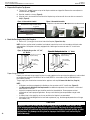
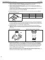
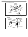
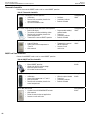
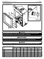
Prepare the Fireplace Top Spacers
1. The two (2) 4” standoff spacers on top of the fireplace cabinet are shipped flat. Remove the screw adjacent to
the detached end (Figure 8).
2. Bend the standoffs as shown (Figure 9):
3. Align the hole in the standoff with the hole in the fireplace top, and secure with the screw that was removed in
Step 1 (Figure 9).
Figure 8: Unassenbled standoff Figure 9: Assembled standoffs
Positioned flat as shipped from the factory
Fireplace Front
Top Standoff
Screw
Configuration for 1/2" finish materials
Fireplace
Front
Top Standoff
Fireplace
Front
Top Standoff
Configuration for 5/8" finish materials
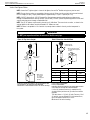
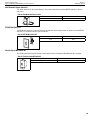
3. Route the Gas Supply Line to the Fireplace
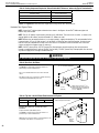
1. Route a 1/2” (13 mm) gas line to the left side of the fireplace (Figure 10 & 10a).
NOTE: Gas lines must be routed, assembled, and made of materials that are in strict accordance with local codes
and regulations. All fireplaces are factory-equipped with a flexible gas line connector and a 1/2” shutoff valve
(Page 39).
Figure 10: Routing the gas line - 35”, 40”,
45” Models
Left side front corner of
fireplace framing
Pipe coupling
(recommended)
7 5/8”
(195 mm)
3”
(76 mm)
Proper Sizing of Gas Line
Properly size and route the gas supply line from the supply regulator to the area where the appliance is to be installed
per requirements outlined in the National Fuel Gas Code, NFPA 54—latest edition (USA) or CAN/CGA-B149.1—
latest edition (Canada).
The gas supply line should not be connected to the appliance until step 12. Connect the Gas Line (Page 38).
NOTE:
• All fireplaces are factory-equipped with a flexible gas line connector and 1/2” shutoff valve (Figure 35).
• See Massachusetts Horizontal Vent Requirements for additional requirements for installations in the state of
Massachusetts in the USA.
• A pipe joint compound rated for gas should be used on the threaded joints. Ensure propane-resistant
compounds are used in propane applications. Be very careful that the pipe compound does not get inside
the pipe.
• A sediment trap in the supply line as close as possible to the fireplace is recommended.
• Check with the local building official for local code requirements (e.g., Are below grade penetrations of the gas
line allowed?, etc).
CAUTION
If propane is used, be aware that with a tank that is too small (i.e., under 100 lbs, if this
is the only gas appliance in the dwelling—see NPFA 58), there may be a loss of pressure.
This can result in insufficient fuel delivery that can cause sooting, delayed ignition, or other
malfunctions. Any damage resulting from an improper installation is not covered by the
limited warranty.
Figure 60: Routing the gas line
Left side front corner of
fireplace framing
Pipe coupling
(recommended)
5 1/4”
(140 mm)
3”
(76 mm)
Figure10a: Routing the Gas Line - 33” Model

Installation
900004-00, 04/2015
Innovative Hearth Products
Superior™ DRT2000 and DRC2000 Direct-Vent Gas Fireplaces
19
4.
Rough in the Electrical Supply, if Needed
1. As necessary, rough in the fireplace electrical supply per NEC and local codes.
5. Install the [Optional] Blower Kit before Installation in the Framing
1. Remove the left side blower cover panel screw, and blower cover panel (Table 13). Retain the panel and screw
for later reinstallation.
2. Slide the blower through the opening and position it with the bracket oriented to the front of the firebox and
the blower discharge to the rear of the firebox. Bend the two tabs in the firebox floor to secure the blower to
the floor.
3. Reinstall the blower cover panel and secure with the removed screw.
4. Access the blower supply wiring through the front of the firebox and plug it into the junction box in the right, rear
of the firebox (Figure 33).
5. Install the blower control switch according to its included instructions.
6. Place the Fireplace in the Framing and Secure
NOTE: Nailing flanges, combustible members, and screw heads in areas directly adjacent to the nailing flanges are
EXEMPT from the 1/2” clearance to combustible requirements for the firebox outer wrapper.
NOTE: Combustible framing may be in direct contact with the nailing flanges and may be located within 1/2” of screw
heads and the firebox wrapper in areas adjacent to the nailing flanges.
Frame the opening to the exact dimensions specified in the framing details in this manual.
1. Bend out the appropriate nailing flanges for the drywall / finish material to be used (Figure 11). Nailing flanges
are provided for:
• flush framing,
• 1/2”, and
• 5/8” framing depths.
2. Secure the fireplace to the side framing members using the unit’s nailing flanges —one top and bottom on each
side of the fireplace front (Figure 11). Use 8d nails or the equivalent.
Figure 11: Nailing Flanges
Side
framing
Unit nailing flange
(no clearance to combustible
framing is required)
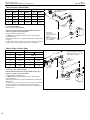
VENT SYSTEM PREPARATION
7. Select a Horizontal or Vertical Vent System
1. With the fireplace secured in the framing, determine the vent route and identify the exterior termination location.
The following sections describe vertical (roof) and horizontal (exterior wall) vent applications. Use only approved
vent components (Page 8 and Page 44).
NOTE: This fireplace must be vented directly to the outside.
WARNING
The vent system may not service multiple appliances, and must never be connected to a
flue serving a separate solid fuel burning appliance.
NOTE: The vent pipe is tested to be run inside an enclosed wall (such as a chase). There is no requirement for
inspection openings in the enclosing wall at any of the joints in the vent pipe.

Installation
900004-00, 04/2015
Innovative Hearth Products
Superior™ DRT2000 and DRC2000 Direct-Vent Gas Fireplaces
20
If you require a rear vent unit, check to see if rear venting has a vent cap and insulation in place. If so, remove cap and
any insulation in vent pipes, make sure flue is open completely to firebox inside. Once flue pipe has clear passages on
inner and outer pipes, proceed with vent connections.
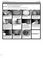
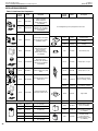
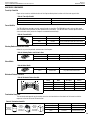
Prepairing 45” Fireplaces for Top Venting Configuration
If you require a top vented unit, follow the next steps to convert before use.
Step 1. Remove the 8 screws
holding top vent cover plate and
gasket. Retain screws.
Step 2. Remove the round flue
cover from top venting outlet
and all insulation from inside
flue inner and outer pipe.
Step 3. Remove all insulation
from inside flue inner and outer
pipe. Retain insulation.
Step 4. If rear vent does not
have a cap already installed,
pack inner and outer pipe with
the insulation from top.
Step 5. Remove and discard
the large round gasket attached
to the back of the unit. Install
the cap from the top onto the
rear pipe by bending tabs out
securing with screws to rear
outer wrapper.
Step 6. Reinstall screws to seal
holes in wrapper.
Step 7. Remove the rear
vertical Baffle from top, retain
screws but discard baffle.
Reinstall screws to seal holes
after vertical baffle is removed.
Discard the vertical baffle.
Step 8. Remove the 2 screws
holding the block off plate and
gasket to top vent flue. Retain
screws as they will be re-used.
Step 9. Remove the 4 screws
around the rear vent and use
to Re-install block off plate and
gasket over the rear vent flue.
Step 10. Using the 2 screws
from the rear vertical baffle,
Install the top baffle (shipped in
bottom of unit) see photo.
Step 11. Ensure flue passage
is clear to inside of firebox,
and that outer pipe is free of
insulation.
Unit is now ready to install
as top-venting fireplace.
La page charge ...
La page charge ...
La page charge ...
La page charge ...
La page charge ...
La page charge ...
La page charge ...
La page charge ...
La page charge ...
La page charge ...
La page charge ...
La page charge ...
La page charge ...
La page charge ...
La page charge ...
La page charge ...
La page charge ...
La page charge ...
La page charge ...
La page charge ...
La page charge ...
La page charge ...
La page charge ...
La page charge ...
La page charge ...
La page charge ...
La page charge ...
La page charge ...
La page charge ...
La page charge ...
La page charge ...
La page charge ...
La page charge ...
La page charge ...
La page charge ...
La page charge ...
La page charge ...
La page charge ...
La page charge ...
La page charge ...
La page charge ...
La page charge ...
La page charge ...
La page charge ...
La page charge ...
La page charge ...
La page charge ...
La page charge ...
La page charge ...
La page charge ...
La page charge ...
La page charge ...
La page charge ...
La page charge ...
La page charge ...
La page charge ...
-
 1
1
-
 2
2
-
 3
3
-
 4
4
-
 5
5
-
 6
6
-
 7
7
-
 8
8
-
 9
9
-
 10
10
-
 11
11
-
 12
12
-
 13
13
-
 14
14
-
 15
15
-
 16
16
-
 17
17
-
 18
18
-
 19
19
-
 20
20
-
 21
21
-
 22
22
-
 23
23
-
 24
24
-
 25
25
-
 26
26
-
 27
27
-
 28
28
-
 29
29
-
 30
30
-
 31
31
-
 32
32
-
 33
33
-
 34
34
-
 35
35
-
 36
36
-
 37
37
-
 38
38
-
 39
39
-
 40
40
-
 41
41
-
 42
42
-
 43
43
-
 44
44
-
 45
45
-
 46
46
-
 47
47
-
 48
48
-
 49
49
-
 50
50
-
 51
51
-
 52
52
-
 53
53
-
 54
54
-
 55
55
-
 56
56
-
 57
57
-
 58
58
-
 59
59
-
 60
60
-
 61
61
-
 62
62
-
 63
63
-
 64
64
-
 65
65
-
 66
66
-
 67
67
-
 68
68
-
 69
69
-
 70
70
-
 71
71
-
 72
72
-
 73
73
-
 74
74
-
 75
75
-
 76
76


Superior DRC2000 Installation And Operation Instructions Manual
- Taper
- Installation And Operation Instructions Manual
dans d''autres langues
- English: Superior DRC2000
Autres documents
-
Astria Fireplaces Altair Mode d'emploi
-
IHP Superior Fireplaces DRC2033REN Mode d'emploi
-
Superior Fireplaces DRT6300 Mode d'emploi
-
-
-
-
-
-
 Vanox Nova VL36BN Operating & Maintenance Instructions
-
