
BCĆ20G
COMBINATION OVEN STEAMER
INSTALLATION - OPERATION - MAINTENANCE
BCĆ20G
COMBIĆFOUR/ÉTUVE À VAPEUR
MANUEL D'INSTALLATION - FONCTIONNEMENT - ENTRETIEN
BLODGETT COMBI
www.blodgett.com
44 Lakeside Avenue, Burlington, Vermont 05401 USA Telephone (800) 331Ć5842, (802) 860Ć3700 Fax: (802)864Ć0183
PN R10869 Rev J (8/10)
E 2010 - Blodgett Combi

A PERSONAL WORD FROM BLODGETT COMBI
QUELQUES MOTS DE BLODGETT COMBI
Congratulations on your purchase of a BLODGETT Combi appliance. We
firmly believe that your choice has been a wise one, and trust you will reĆ
ceive many years of excellent service from your new Combi.
You will find that cooking with Combi appliances saves time, labor and
extensive cleaning of both the kitchen and the unit.
With Combi appliances the quality, taste, consistency, and look of your
food are improved, thus endorsing the policy to which we've always adĆ
hered: For Better Cooking!"
Once you've had a chance to use your Combi, please tell us, your dealer
and colleagues about any creative and interesting applications you have
discovered; exchange ideas with other users. Be sure to advise us or
your dealer immediately should any mechanical or technical problems
be encountered (...we're here to help!) and above all Enjoy Cooking the
BLODGETT Combi Way!
For information on cooking, please refer to our separate cooking guide.
Toutes nos félicitations sur votre achat d'appareil de Blodgett Combi.
Nous croyons fermement que votre choix est un choix raisonnable et
nous sommes certains que vous obtiendrez de nombreuses années
d'excellent service de votre nouveau four multiĆusages.
Vous allez découvrir que la cuisson dans les appareils Combi économise
le temps, le travail et le degré de nettoyage de l'appareil aussi bien que
de la cuisine.
Avec les appareil de Combi, la qualité, le goût, la consistence et l'apparĆ
ence des aliments sont améliorés, s'accordant, de ce fait, avec notre
politique "Pour une meilleure cuisson !"
Une fois que vous aurez eu la chance d'utiliser notre Combi, informez
nous, votre concessionnaire et vos collègues, de toutes les applications
nouvelles et intéressantes que vous avez découvertes ; échangez vos
idées avec d'autres utilisateurs. N'hésitez pas à nous prévenir, ou votre
concessionnaire, de tout problème mécanique ou technique que vous
pourriez rencontrer (... nous sommes ici pour vous aider) et parĆdessus
tout RégalezĆvous à cuisiner à la façon BLODGETT Combi!
Pour obtenir de plus amples informations sur l'art culinaire, veuillez conĆ
sulter notre livre de cuisine séparé.

IMPORTANT
FOR YOUR SAFETY
Do not store or use gasoline or other flammable vapors or liquids in the vicinity
of this or any other appliance.
AVERTISSEMENT
Ne pas entreposer ni utiliser de l'essence ni d'autres vapeurs ou liquides inflamĆ
mables dans le voisinage de cet appariel, ni de tout autre appareil.
INSTRUCTIONS TO BE FOLLOWED IN THE EVENT THE USER SMELLS GAS
MUST BE POSTED IN A PROMINENT LOCATION. THIS INFORMATION MAY BE
OBTAINED BY CONTACTING YOUR LOCAL GAS SUPPLIER.
LES INSTRUCTIONS À RESPECTER AU CAS OÙ L'UTILISATEUR PERÇOIT UNE
ODEUR DE GAZ DOIVENT ÊTRE AFFICHÉES DANS UN ENDROIT BIEN VISIBLE.
VOUS POUVEZ VOUS LES PROCURER AUPRÈS DE VOTRE FOURNISSEUR DE
GAZ LOCAL.
WARNING: IMPROPER INSTALLATION, ADJUSTMENT, ALTERATION, SERVICE OR
MAINTENANCE CAN CAUSE PROPERTY DAMAGE, INJURY OR DEATH. READ THE
INSTALLATION, OPERATING AND MAINTENANCE INSTRUCTIONS THOROUGHLY
BEFORE INSTALLING OR SERVICING THIS EQUIPMENT
AVERTISSEMENT: UNE INSTALLATION, UN AJUSTEMENT, UNE ALTÉRATION, UN
SERVICE OU UN ENTRETIEN NON CONFORME AUX NORMES PEUT CAUSER DES
DOMMAGES À LA PROPRIÉTE, DES BLESSURES OU LA MORT. LISEZ ATTENTIVEĆ
MENT LES DIRECTIVES D'INSTALLATION, D'OPÉRATION ET D'ENTRETIEN AVANT
DE FAIRE L'INSTALLATION OU L'ENTRETIEN DE CET ÉQUIPEMENT.
The information contained in this manual is important for the proper installation,
use, and maintenance of this oven. Adherence to these procedures and instrucĆ
tions will result in satisfactory baking results and long, trouble free service.
Please read this manual carefully and retain it for future reference.
Les informations données dans le présent manuel sont importantes pour installer,
utiliser et entretenir correctement ce four. Le respect de ces instructions et procéĆ
dures permettra d'obtenir de bons résultats de cuisson et une longue durée de serĆ
vice sans problèmes. Veuillez lire le présent manuel et le conserver pour pouvoir
vous y reporter à l'avenir.
Errors: Descriptive, typographic or pictorial errors are subject to correction. SpecificaĆ
tions are subject to change without notice.
Erreurs:Les erreurs de description, de typographie ou d'illustration font l'objet de
corrections. Les caractéristiques sont sujettes à modifications sans préavis.

Your Service Agency's Address:
Adresse de votre agence de service:
Model/Modèl:
Serial Number/Numéro de série:
Your oven was installed by/
Installateur de votre four:
Your oven's installation was checked by/
Contrôleur de l'installation de votre four:

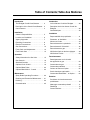
Table of Contents/Table des Matières
Introduction
The Blodgett CombiĆOven/Steamer 2. . . . .
Description of the CombiĆOven/Steamer 3.
Oven Features 4. . . . . . . . . . . . . . . . . . . . . . .
Installation
Owner's Responsibilities 5. . . . . . . . . . . . . . .
Location and Ventilation 6. . . . . . . . . . . . . . .
Agency Approvals 7. . . . . . . . . . . . . . . . . . . .
Plumbing Connections 8. . . . . . . . . . . . . . . .
Electrical Connections 9. . . . . . . . . . . . . . . .
Gas Connections 10. . . . . . . . . . . . . . . . . . . . .
Final Check and Adjustments 12. . . . . . . . . .
Final Check Lists 13. . . . . . . . . . . . . . . . . . . . .
Operation
Safety Information for Gas Units 15. . . . . . . .
Gas Controls 16. . . . . . . . . . . . . . . . . . . . . . . . .
Standard Controls 17. . . . . . . . . . . . . . . . . . . .
Optional Cook & Hold 19. . . . . . . . . . . . . . . . .
Optional Meat Probe 23. . . . . . . . . . . . . . . . . .
Optional MenuSelectt Control 24. . . . . . . . .
Maintenance
Spray Bottle Operating Procedure 30. . . . . .
Cleaning and Preventive Maintenance 31. . .
Deliming 32. . . . . . . . . . . . . . . . . . . . . . . . . . . . .
Communication 35. . . . . . . . . . . . . . . . . . . . . .
Introduction
Le fourĆétuveur Combi de Blodgett 38. . . . . .
Description de le fourĆétuveur Combi de
Blodgett 39. . . . . . . . . . . . . . . . . . . . . . . . . . . . .
Caractéristiques 40. . . . . . . . . . . . . . . . . . . . . .
Installation
Responsabilités du propriétaire 41. . . . . . . . .
Placement et Ventilation 43. . . . . . . . . . . . . .
Normes et Codes 44. . . . . . . . . . . . . . . . . . . . .
Raccordement de la plomberie 45. . . . . . . . .
Raccordement à l'électricité 46. . . . . . . . . . . .
Raccordement au gaz 47. . . . . . . . . . . . . . . . .
Vérification finale et derniers réglages 49. . .
Vérifications Finales 50. . . . . . . . . . . . . . . . . . .
Fonctionnement
Renseignements sur la sécurité
des appareils au gaz 52. . . . . . . . . . . . . . . . . .
Commandes du gaz 53. . . . . . . . . . . . . . . . . .
Commandes standard 54. . . . . . . . . . . . . . . .
Cuisson et Pause en Option 56. . . . . . . . . . .
Sonde thermique optionnelle 61. . . . . . . . . . .
Commande MenuSelectt en Option 62. . . .
Entretien
Procédure de fonctionnement du
pulvérisateur 70. . . . . . . . . . . . . . . . . . . . . . . . .
Nettoyage et entretien préventif 71. . . . . . . .
Détartrage 73. . . . . . . . . . . . . . . . . . . . . . . . . . .
Communications 77. . . . . . . . . . . . . . . . . . . . .

Introduction
2
The Blodgett CombiĆOven/Steamer
The Blodgett CombiĆOven/Steamer offers a comĆ
pletely new method of cooking. With the Oven/
Steamer you have the choice of two cooking proĆ
cesses: Steam and Hot Air, either...
D Separately
D Combined, or
D In Sequence
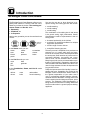
And for easy operation you can choose from three
modes:
Steam Hot Air
Combi
Steam &
Hot Air
In the Steam mode you can:
steam reheat reconstitute
stew thaw simmer
blanch preserve braise
poach
In the Hot Air mode you can:
roast bake
grill gratinate
broil
In the Combination, Steam, and Hot Air mode
you can:
defrost roast rethermalize
reheat bake forced steaming
You āācan also āāuse āātwo āāor āthree functions in seĆ
quence during one cooking process. We call this:
D combiĆsteaming
D combiĆroasting
D combiĆbaking
The combination of circulating hot air and steam
in the space saving, high performance CombiĆ
Oven/Steamer leads to improvements in the folĆ
lowing areas:
D increased productivity in the kitchen
D a reduction in capital expenditures for multiple
equipment replacement
D a wider range of menu choices
D a simplified cleaning process
The work process is simplified since products are
prepared on or in steam table āpans āand trays.
Food can be cooked, stored, and transported with
āthe āsame āāpans. āSmall āamounts of product can be
processed efficiently; preĆcooked and conveĆ
nience foods can be reheated within minutes.
āMany frozen foods can be processed without preĆ
thawing. This flexibility in preparation reduces the
need for kettles and steam tables since there is no
need for large amounts of food to be kept warm for
long periods of time.
Today the improvement of food quality is more imĆ
portant than ever. Vegetables are cooked in the
Blodgett CombiĆOven/Steamer without water at
the optimal temperature of just under 100_C
(212_F), maintaining valuable vitamins, minerals,
nutrients and trace elements. Cooking meat in the
Combi results in less shrinkage and a firmer, juicier
product. The Blodgett CombiĆOven/Steamer is
being used more and more for baking. Steam and
Hot āAir āmodes āmake āit āa āgeneral āpurpose baking
appliance.

Introduction
3
Description of the CombiĆOven/Steamer
ABOUT THE OVEN/STEAMER
Blodgett CombiĆOven/Steamers are quality proĆ
duced using highĆgrade stainless steel with first
class workmanship.
The two speed fan, which is guarded against acciĆ
dental finger contact, is driven by a quiet and powĆ
erful motor. The condenser draws out excess
steam from the appliance. Condensation and
waste water, which result during steaming and
cleaning, are continuously drained.
The use of high quality insulation impedes excesĆ
sive heat radiation and saves energy.
The high performance fresh steam generator with
its control system makes it possible to enjoy all of
the advantages of a high quality steamer at the
flick of a switch. Fresh steam enters the oven cavĆ
ity without pressure and is circulated at high
speed. This process enables quick and gentle
cooking and ensures high quality food while proĆ
viding convenient working methods. The steam
generator is completely automatic and protected
from running dry.
OVEN/STEAMER OPERATION
The practical oven door, with a viewing window,
has a wide swing radius and handle which can be
operated easily, even with wet or greasy hands.
Ease of operation is guaranteed through the simĆ
ple arrangement of the controls. Graphic symbols
make the appliance easy for even inexperienced
kitchen staff to operate. Steam, Hot Air and Combi
modes can be selected with one switch. The
Steam On Demand feature allows the operator to
add steam at any time for up to 8 minutes while opĆ
erating in either the hot air or Combi modes. This
feature is excellent for baking as well as roasting
operations. A fourth function on the mode selecĆ
tion switch, the Cool Down mode, allows the oven
cavity to cool down rapidly with the door opened.
The steam on demand function allows the operaĆ
tor the ability to introduce steam into the cooking
process at any time.
Cleaning is kept to a minimum. The interior is
sprayed with a selfĆacting cleaning solution which
interacts with steam to easily remove crusts and
stains. The oven is designed for easy care and is
welded water tight so that the internal cooking
cavity may be rinsed with a hose after the steam
cleaning process.

Introduction
4
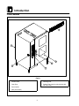
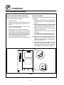
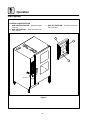
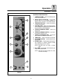
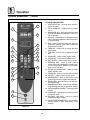
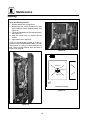
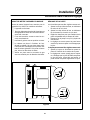
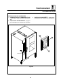
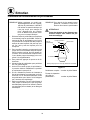
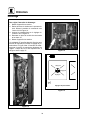
Oven Features
1
2
3
5
4
6
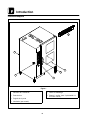
Figure 1
1 Control Panel
2 Oven Door
3 Door Handle
4 VentĂ(not shown)
5 Deliming Inlet
6 Sealing Plate (used to preheat oven withĆ
out rollĆin cart)

Installation
5
Owner's Responsibilities
1. Oven(s) are uncrated and put in place.
2. The owner/operator must have the following
plumbing, gas and electrical requirements
met and installed.
NOTE: Refer to the Utility Connection inforĆ
mation provided.
WARNING!!
Improper installation, adjustment, alterĆ
ation service or maintenance can cause
property damage, injury or death. Read
the installation, operation and mainteĆ
nance instruction thoroughly before inĆ
stalling or servicing this equipment.
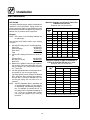
ELECTRICAL - BCĆ20G
115V - 15 amp Nema 5Ć15 receptacle
208/240V - 20 amp Nema 6Ć20 receptacle
PLUMBING - BCĆ20G
Water
Water Pressure (min/max) 40 PSI min/50 PSI max
Water Connection 3/4" Hose Fitting, 3/8" ID hose minimum
Pressure Regulator Setting 35 PSI Preset
Minimum Requirements TDS - less than 100 parts per million
Total Hardness - 80Ć120 parts per million
Chlorides -less than 30 parts per million
Chlorine - 0 parts per million
pH Factor - 7.0Ć8.0
Drainage Atmospheric Vented Drain
Drain Connection 2" NPT
Avg Water Drain Temp. 122_F (50_C)
GAS PRESSURE - BCĆ20G
Gas Input
Steam 90,000 BTU/HR
Hot Air 125,000 BTU/HR
Inlet Pressure to the Unit
Natural Gas 5-14" WC (1.24-3.48 kPa)
Propane 11-14" WC (2.73-3.48 kPa)
Pressure at the Manifold
Natural Gas 3.5" WC (.87 kPa)
Propane 10" WC (2.49 kPa)
1" FNPT connector for all US and Canadian installations

Installation
6
Location and Ventilation
LOCATION
The well planned and proper placement of your
appliance will result in long term operator conveĆ
nience and satisfactory performance.
The following clearances must be maintained beĆ
tween the unit and any combustible or nonĆcomĆ
bustible construction.
BCĆ20G
D Right side of unit - 6" (15 cm)
D Left side of unit - 6" (15 cm)
D Back of unit - 6" (15 cm)
The following clearances are recommended, but
not required, for servicing.
D Left side of unit - 12" (30 cm)
D Back of unit - 12" (30 cm)
Place the unit in an area which is free of drafts and
accessible for proper operation and servicing.
Keep the operating area free and clear of all comĆ
bustibles such as paper, cardboard, and flamĆ
mable liquids and solvents.
DO NOT place the unit on a curb base or seal to
the wall; either condition will prevent proper ventiĆ
lation to the blower motors. Slight unevenness can
be corrected with the adjustable legs.
All motor bearings are permanently lubricated by
the manufacturer; there is no need for additional
lubrication during the operational lifetime of the
motors.
VENTILATION
The necessity for a properly designed and inĆ
stalled ventilation system cannot be over emphaĆ
sized. The ventilation system will allow the unit to
function properly while removing unwanted vaĆ
pors and products of combustion from the operatĆ
ing area.
The appliance must be vented with a properly deĆ
signed mechanically driven exhaust hood. The
hood should be sized to completely cover the
equipment plus an overhang of at least 6" (15 cm)
on all sides not adjacent to a wall. The capacity of
the hood should be sized appropriately and proviĆ
sions made for adequate makeup air.
WARNING!!
Failure to properly vent the oven can be
hazardous to the health of the operator;
and will result in operational problems,
unsatisfactory baking, and possible damĆ
age to the equipment. Damage sustained
as a direct result of improper ventilation
will not be covered by the Manufacturer's
warranty.
When installed in the Commonwealth of MassaĆ
chusetts, this appliance must be interlocked with
the hood exhaust system so that the appliance
may be operated only when the hood exhaust sysĆ
tem is running.
U.S. and Canadian Installations
Refer to your local ventilation codes. In the abĆ
sence of local codes, refer to the National ventilaĆ
tion code titled, Standard for the Installation of
Equipment for the Removal of Smoke and Grease
Laden Vapors from Commercial Cooking EquipĆ
ment", NFPAĆ96Ć Latest Edition.
General Export Installations
Installation must conform with Local and National
installation standards. Local installation codes
and/or requirements may vary. If you have any
questions regarding the proper installation and/or
operation of your unit, please contact your local
distributor. If you do not have a local distributor,
please call Blodgett Combi at 0011Ć802Ć860Ć3700.

Installation
7
Agency Approvals
THE INSTALLATION INSTRUCTIONS CONĆ
TAINED HEREIN ARE FOR THE USE OF QUALIĆ
FIED INSTALLATION AND SERVICE PERSONNEL
ONLY. INSTALLATION OR SERVICE BY OTHER
THAN QUALIFIED PERSONNEL MAY RESULT IN
DAMAGE TO THE OVEN AND/OR INJURY TO
THE OPERATOR.
Qualified installation personnel are individuals, a
firm, a corporation, or a company which either in
person or through a representative are engaged
in, and are responsible for:
D The installation or replacement of gas piping.
The connection, installation, repair or servicing
of equipment.
D The installation of electrical wiring from the elecĆ
tric meter, main control box or service outlet to
the electric appliance.
Qualified installation personnel must be experiĆ
enced in such work, be familiar with all precauĆ
tions required and have complied with all requireĆ
ments of state or local authorities having
jurisdiction.
U.S. and Canadian Installations
Installation must conform with local codes, or in
the absence of local codes, with the National Fuel
Gas Code, NFPA54/ANSI Z223.1-Latest Edition,
the Natural Gas and Propane Installation Code
CAN/CSAĆB149.1.
Reference: National Electrical Code, ANSI/NFPA
70-Latest Edition and/or Canadian Electrical
Code CSA C22.1 as applicable.
This equipment is to be installed in compliance
with the Basic Plumbing Code of the Building OffiĆ
cials and Code Administrators International Inc.
(BOCA) and the Food Service Sanitation Manual of
the Food and Drug Administration (FDA).
Appliance is to be installed with backflow prevenĆ
tion in accordance with applicable federal, provĆ
ince and local codes.
General Export Installations
Installation must conform with Local and National
installation standards. Local installation codes
and/or requirements may vary. If you have any
questions regarding the proper installation and/or
operation of your unit, please contact your local
distributor. If you do not have a local distributor,
please call Blodgett Combi at 0011Ć802Ć860Ć3700.

Installation
8
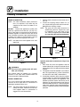
Plumbing Connections
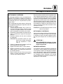
WATER CONNECTION
NOTE: Hot water maximizes steam production
but is not required. Cold water may be
supplied to both inlets if hot water is not
available.
BCĆ20G - Connect the appliance to quality cold
water via a pressure hose with 3/4" (1/9 cm) couĆ
plings. Cold water is connected to the left solenoid/
pressure regulator as viewed from the rear of the
oven. Hot water connection, right solenoid/pressure
regulator, to the boiler is recommended. A shut off
valve must be provided adjacent to the oven.
NOTE: Hot water must not be applied to the cold
water inlet.
1/2" Appliance Hose
With 3/4" Hose Fittings
Figure 2
WARNING!!
The use of poor quality water will invaliĆ
date your warranty.
This product must be installed by a licensed
Plumber or Gas Fitter when installed within the
Commonwealth of Massachusetts.
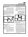
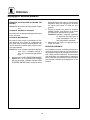
DRAIN CONNECTION
A 2" (5 cm) copper pipe with standard drain pitch
must be run to an open drain or connected to a
standpipe equipped with a vent.
NOTE: The waste water can also be directed to a
nearby floor drain. Flexible hose which alĆ
lows trapped water to accumulate in
sagged runs must be avoided.
1. Find the drain connection on the lower rear of
the unit.
2. Loosen the coupling clamps. Attach a 2" (5
cm) copper drain pipe to the drain connection.
Retighten the coupling clamps.
NOTE: The open end of the drain should be inĆ
stalled facing the floor. Copper line, used
for installation to an open drain or floor
sink, must be supplied by the installer. Use
of a trap inline will cause drain backup.
2" Drain
Customer
Supplied
To Drain
Oven
Drain
Figure 3
Specific water/drain connection for City of Los
Angeles
1. Each drain line from the appliance shall be
routed without dips or sags to terminate above
the flood level rim of an approved indirect waste
receptor.
2. The appliance shall be installed in accordance
with the manufacturer's printed instructions
and the LAPC and LAMC, 1999 editions.
3. A backflow protection device may be required
by local codes. If so, install on the potable water
system directly ahead of the appliance. The
backflow protection device shall be any of the
following: an approved pressure type vacuum
breaker installed at least 12" above the highest
point of use, a double check valve backflow preĆ
venter or a reduced pressure principal backflow
preventer.

Installation
9
Electrical Connections
Before making any electrical connections to these
units, check that the power supply is adequate for
the voltage, amperage, and phase requirements
stated on the rating name plate mounted on the
right side of the unit.
Wiring diagrams are located on the inside of the
removable side panel.
NOTE: DISCONNECT THE POWER SUPPLY TO
THE UNIT BEFORE SERVICING!
U.S. and Canadian installation
All units, when installed, must be electrically
grounded in accordance with local codes or in the
absence of local codes, with the National Electrical
Code, ANSI/NFPA 70-Latest Edition and/or CanaĆ
dian Electrical Code CSA C22.1 as applicable.
General Export Installations
Installation must conform with Local and National
installation standards. Local installation codes
and/or requirements may vary. If you have any
questions regarding the proper installation and/or
operation of your unit, please contact your local
distributor. If you do not have a local distributor,
please call Blodgett Combi at 0011Ć802Ć860Ć3700.
WARNING!!
Improper electrical installation will invaliĆ
date your warranty.
Gas Models
U.S. and Canadian Installations
A power cord (115V or 230V) is supplied with a
plug attached. Plug the power cord into the deĆ
sired receptacle.
WARNING!!
If the supply cord is damaged, it must be
replaced by a special cord or assembly
available from the manufacturer or its serĆ
vice agent.

Installation
10
Gas Connections
GAS PIPING
A properly sized gas supply system is essential for
maximum oven performance. Piping should be
sized to provide a supply of gas sufficient to meet
the maximum demand of all appliances on the line
without loss of pressure at the equipment.
Example:
NOTE: BTU values in the following example are
for natural gas.
You purchase a BCĆ20G to add to your existing
cook line.
1. Add the BTU rating of your current appliances.
Pitco Fryer 120,000 BTU
6 Burner Range 60,000 BTU
Deck Oven 50,000 BTU
Total 230,000 BTU
2. Add the BTU rating of the new oven to the toĆ
tal.
Previous Total 230,000 BTU
BCĆ20G (for hot air) 125,000 BTU
New Total 355,000 BTU
3. Measure the distance from the gas meter to
the cook line. This is the pipe length. Let's say
the pipe length is 20' (6 m) and the pipe size
is 1" (2.54 cm).
4. Use the appropriate table to determine the toĆ
tal capacity of your current gas piping.
The total capacity for this example is 465,000
BTU. Since the total required gas pressure,
355,000 BTU is less than 465,000 BTU, the
current gas piping will not have to be inĆ
creased.
NOTE: The BTU capacities given in the tables are
for straight pipe lengths only. Any elbows
or other fittings will decrease pipe capaciĆ
ties. For example: a schedule 40Ć1/2" elĆ
bow fitting has an equivalent cpapacity of
4.2" (10.2 cm) of straight pipe. Contact
your local gas supplier if you have any
questions.
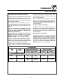
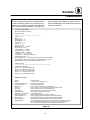
Maximum Capacity of Iron Pipe in Cubic Feet
of Natural Gas Per Hour
(Pressure drop of 0.5 Inch W.C.)
Pipe
Length
Nominal Size, Inches
L
eng
th
(ft)
3/4" 1" 1Ć1/4" 1Ć1/2" 2"
10 360 680 1400 2100 3950
20 250 465 950 1460 2750
30 200 375 770 1180 2200
40 170 320 660 990 1900
50 151 285 580 900 1680
60 138 260 530 810 1520
70 125 240 490 750 1400
80 118 220 460 690 1300
90 110 205 430 650 1220
100 103 195 400 620 1150
From the National Fuel Gas Code Part 10 Table 10Ć2
Maximum Capacity of Pipe in Thousands of
BTU/hr of Undiluted P.P. Gas at 11" W.C.
(Pressure drop of 0.5 Inch W.C.)
Pipe Length
(ft)
Inside Diameter, Inches
pg
(ft)
3/4" 1" 1Ć1/2"
10 608 1146 3525
20 418 788 2423
30 336 632 1946
40 287 541 1665
50 255 480 1476
60 231 435 1337
70 215 404 1241
80 198 372 1144
90 187 351 1079
100 175 330 1014
From the National Fuel Gas Code Part 10 Table 10Ć15

Installation
11
Gas Connections
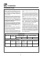
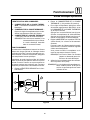
PRESSURE REGULATION AND TESTING
The gas pressure to the appliance must be rated
for each appliance while the burners are on. A sufĆ
ficient gas pressure must be present at the inlet to
satisfy these conditions. Refer to the table below
for correct gas pressure.
Each appliance has been adjusted at the factory
to operate with the type of gas specified on the ratĆ
ing plate attached to the right side of the apĆ
pliance.
Each oven is supplied with a regulator to maintain
the proper gas pressure. The regulator is essenĆ
tial to the proper operation of the oven and
should not be removed.
DO NOT INSTALL AN ADDITIONAL REGULATOR
WHERE THE UNIT CONNECTS TO THE GAS
SUPPLY UNLESS THE INLET PRESSURE IS
GREATER THAN 14" W.C. (1/2 PSI) (37mbar).
The oven and its individual shutoff valve must be
disconnected from the gas supply piping system
during any pressure testing of that system at test
pressures in excess of 1/2 psig (3.45kPa).
The oven must be isolated from the gas supply
piping system by closing its individual manual
shutoff valve during any pressure testing of the
gas piping system at test pressures equal or less
than 1/2 psig (3.45kPa).
Prior to connecting the appliance, gas lines
should be thoroughly purged of all metal filings,
shavings, pipe dope, and other debris. After conĆ
nection, the appliance must be checked for corĆ
rect gas pressure.
U.S. and Canadian Installations
Installation must conform with local codes, or in
the absence of local codes, with the National Fuel
Gas Code, NFPA54/ANSI Z223.1-Latest Edition,
the Natural Gas and Propane Installation Code
CAN/CSAĆB149.1.
General Export Installations
Installation must conform with Local and National
installation standards. Local installation codes and/
or requirements may vary. If you have any questions
regarding the proper installation and/or operation of
your appliance, please contact your local distributor.
If you do not have a local distributor, please call
Blodgett Combi at 0011Ć802Ć860Ć3700.
GAS PRESSURE
Gas
T
Inlet
P
Orifice Size at Sea Level Manifold Pressure
Type Pressure
Hot Air Steam Hot Air Steam
U.S. and Canadian Installations
Natural 5-14" W.C. 1/16"
.0625" dia
#58
.042" dia
3.5" W.C. 3.5" W.C.
Propane 11-14" W.C. #62
.0380" dia
#70
.0280" dia
10" W.C. 10" W.C.

Installation
12
Final Check and Adjustments
BEFORE SWITCHING THE APPLIANCE ON
Before applying power to the unit for the first time,
check for the following conditions:
j The unit is level.
j All āelectricalā safety provisions have been adĆ
hered to and the electrical connections are
correct.
j Water is connected, turned on and all of the
connections are water tight.
j Grease filters are in their proper positions
j The transport cart is inserted into the cooking
cavity. When the cart is not inserted into the unit,
water can spill onto the floor causing it to beĆ
come slippery. If the door will not close properly,
use the following adjustment procedure.
j Check gas fittings with leak detection solution.
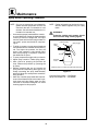
DOOR ADJUSTMENT
The hinges may be adjusted using the following
procedure:
1. Adjust the top hinge plate by loosening the
three mounting bolts on the top right corner of
the unit.
2. Adjust the bottom hinge pin by loosening the
mounting bolt located under the bottom hinge
plate on the lower right corner of the oven.
3. Adjustā the hinges āso āthatā the door back and
the unit face are parallel.
4. Tighten the bolts so that there is no further
movement.
5. The āadjustment āis ācorrect āwhen āthe ādoor closes
firmly and no steam leaks from the gasket.
The hinges can also be adjusted as follows:
1. Adjust the door catch by loosening the four
mounting screws located on the inside surĆ
face of the oven door.
2. The āadjustment āis ācorrect āwhen no steam
leaks from the gasket. DO NOT over comĆ
press the door gasket. When closed the door
should slightly compress the door gasket.
Oven
Door
Oven
Door
Figure 4

Installation
13
Final Check Lists
WARNING!!
Final check list must be performed by a
qualified installer only.
ELECTRICAL CONTROL COMPARTMENT
j Voltage to appliance matches rating plate
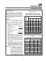
PLUMBING FINAL CHECK
j Incoming water pressure within appliance
specification.
j Atmospheric vented drain in place.
j Water solenoid properly bracketed and not
leaking.
j Water feed lines intact without leaks.
j Optional Spray Hose connected properly.
Connect the optional spray hose to the fill soĆ
lenoid as shown.
To
Oven Fill
Manifold
Hose and Spray
Option
Cold Water Supply
Figure 5

Installation
14
Final Check Lists
WARNING!!
Final check list must be performed by a
qualified installer only.
ELECTRICAL CONTROL COMPARTMENT
j Voltage to appliance matches rating plate
PLUMBING FINAL CHECK
j Incoming water pressure within appliance
specification.
j Atmospheric vented drain in place.
j Water feed lines intact without leaks.
j Ensure proper clearance.
j Delime system has been primed.
OVEN OPERATIONAL TESTS
NOTE: Checks to be made by customer or authoĆ
rized service agent.
Cool Down Mode
j Check that the fan runs with the door open.
Steam Mode
Place in STEAM mode and set thermostat to
212_F (100_C). Verify the following:
j Heat demand lamp is on.
j Heat demand lamp shuts off at approximately
212_F (100_C).
j Set timer for 1 minutet. Press to count
down. Be sure the buzzer sounds when the
time expires.
j Unit produces steam, window fogs, door seal
does not leak.
Combi Mode
Place in COMBI mode, set thermostat to 350_F
(177_C) and verify:
j Heat demand lamp is on (manual and digital
controls only).
j Oven is heating.
j Heat demand lamp shuts off at 350_F (177_C)
and oven maintains 350_F (177_C) (manual
and digital controls only).
j Fan shuts off with door open.
Hot Air Mode
Place in HOT AIR mode and set thermostat to
400_F (204_C) and verify:
j Heat demand lamp is on.
j Oven is heating.
j Heat demand lamp shuts off at 400_F (204_C)
and oven maintains 400_F (204_C).
j Fan shuts off with door open.
Steam On Demand Mode
Place in Hot Air mode. Set Steam On Demand for
1 minute. Press the Steam On Demand button and
verify:
j Steam demand lamp is on.
j Steam demand lamp shuts off after approxiĆ
mately 1 minute.
Fan Speed
j Ensure both fan speeds work.

Operation
15
Safety Information for Gas Units
THE INFORMATION CONTAINED IN THIS SECĆ
TION IS PROVIDED FOR THE USE OF QUALIFIED
OPERATING PERSONNEL. QUALIFIED OPERATĆ
ING PERSONNEL ARE THOSE WHO HAVE
CAREFULLY READ THE INFORMATION CONĆ
TAINED IN THIS MANUAL, ARE FAMILIAR WITH
THE FUNCTIONS OF THE OVEN AND/OR HAVE
HAD PREVIOUS EXPERIENCE WITH THE OPĆ
ERATION OF THE EQUIPMENT DESCRIBED. ADĆ
HERENCE TO THE PROCEDURES RECOMĆ
MENDED HEREIN WILL ASSURE THE
ACHIEVEMENT OF OPTIMUM PERFORMANCE
AND LONG, TROUBLEĆFREE SERVICE.
Please take the time to read the following safety
and operating instructions. They are the key to the
successful operation of your Blodgett Combi apĆ
pliance.
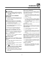
SAFETY TIPS
For your safety read before operating
What to do if you smell gas:
D DO NOT try to light any appliance.
D DO NOT touch any electrical switches.
D Use an exterior phone to call your gas supplier
immediately.
D If you cannot reach your gas supplier, call the
fire department.
What to do in the event of a power failure:
D Turn all switches to off.
D DO NOT attempt to operate the appliance until
the power is restored.
NOTE: In the event of a shutĆdown of any kind, alĆ
low a five (5) minute shut off period before
attempting to restart the oven.
General safety tips:
D DO NOT use tools to turn off the gas control. If
the gas cannot be turned off manually do not try
to repair it. Call a qualified service technician.
D If the oven needs to be moved for any reason,
the gas must be turned off and disconnected
from the appliance before removing the reĆ
straint cable. Reconnect the restraint after the
oven has been returned to its original location.
D DO NOT remove the control panel cover unless
the oven is unplugged.

Operation
16
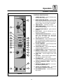
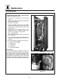
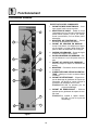
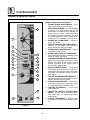
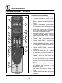
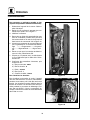
Gas Controls
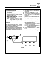
CONTROLS IDENTIFICATION
1. GAS CONTROL SWITCH - Used to turn gas
on or off.
2. GAS ON POSITION - Press the switch into
the I position.
3. GAS OFF POSITION - Press the switch into
the O position.
1
2
3
See View A
Figure 6
La page est en cours de chargement...
La page est en cours de chargement...
La page est en cours de chargement...
La page est en cours de chargement...
La page est en cours de chargement...
La page est en cours de chargement...
La page est en cours de chargement...
La page est en cours de chargement...
La page est en cours de chargement...
La page est en cours de chargement...
La page est en cours de chargement...
La page est en cours de chargement...
La page est en cours de chargement...
La page est en cours de chargement...
La page est en cours de chargement...
La page est en cours de chargement...
La page est en cours de chargement...
La page est en cours de chargement...
La page est en cours de chargement...
La page est en cours de chargement...
La page est en cours de chargement...
La page est en cours de chargement...
La page est en cours de chargement...
La page est en cours de chargement...
La page est en cours de chargement...
La page est en cours de chargement...
La page est en cours de chargement...
La page est en cours de chargement...
La page est en cours de chargement...
La page est en cours de chargement...
La page est en cours de chargement...
La page est en cours de chargement...
La page est en cours de chargement...
La page est en cours de chargement...
La page est en cours de chargement...
La page est en cours de chargement...
La page est en cours de chargement...
La page est en cours de chargement...
La page est en cours de chargement...
La page est en cours de chargement...
La page est en cours de chargement...
La page est en cours de chargement...
La page est en cours de chargement...
La page est en cours de chargement...
La page est en cours de chargement...
La page est en cours de chargement...
La page est en cours de chargement...
La page est en cours de chargement...
La page est en cours de chargement...
La page est en cours de chargement...
La page est en cours de chargement...
La page est en cours de chargement...
La page est en cours de chargement...
La page est en cours de chargement...
La page est en cours de chargement...
La page est en cours de chargement...
La page est en cours de chargement...
La page est en cours de chargement...
La page est en cours de chargement...
La page est en cours de chargement...
La page est en cours de chargement...
La page est en cours de chargement...
La page est en cours de chargement...
-
 1
1
-
 2
2
-
 3
3
-
 4
4
-
 5
5
-
 6
6
-
 7
7
-
 8
8
-
 9
9
-
 10
10
-
 11
11
-
 12
12
-
 13
13
-
 14
14
-
 15
15
-
 16
16
-
 17
17
-
 18
18
-
 19
19
-
 20
20
-
 21
21
-
 22
22
-
 23
23
-
 24
24
-
 25
25
-
 26
26
-
 27
27
-
 28
28
-
 29
29
-
 30
30
-
 31
31
-
 32
32
-
 33
33
-
 34
34
-
 35
35
-
 36
36
-
 37
37
-
 38
38
-
 39
39
-
 40
40
-
 41
41
-
 42
42
-
 43
43
-
 44
44
-
 45
45
-
 46
46
-
 47
47
-
 48
48
-
 49
49
-
 50
50
-
 51
51
-
 52
52
-
 53
53
-
 54
54
-
 55
55
-
 56
56
-
 57
57
-
 58
58
-
 59
59
-
 60
60
-
 61
61
-
 62
62
-
 63
63
-
 64
64
-
 65
65
-
 66
66
-
 67
67
-
 68
68
-
 69
69
-
 70
70
-
 71
71
-
 72
72
-
 73
73
-
 74
74
-
 75
75
-
 76
76
-
 77
77
-
 78
78
-
 79
79
-
 80
80
-
 81
81
-
 82
82
-
 83
83


dans d''autres langues
Documents connexes
-
Blodgett BC-20G Mode d'emploi
-
Blodgett BLCM-102G Mode d'emploi
-
-
-
-
-
Blodgett BCM-102 Mode d'emploi
-
-
-