
Copyright©Briggs & Stratton Corporation
Milwaukee, WI, USA. All Rights Reserved.
80086994
Revision B
Not for
Reproduction

2
Table of Contents:
Where to Find Us..................................................................3
For Future Reference........................................................... 3
Important Safety Instructions..............................................3
Safety Alert Symbol and Signal Words............................ 3
Symbols and Meanings....................................................3
Safety Messages..............................................................3
Installation............................................................................. 5
Installer Responsibilities................................................... 5
Owner Responsibilities..................................................... 5
Equipment Description..................................................... 5
Delivery Inspection........................................................... 5
Mounting Guidelines.........................................................6
Power Wiring Interconnections.........................................6
System Setup (for GC1031 Controller and TRCM
Board)............................................................................. 10
System Setup (for Standard Controller and TRCM
Board)............................................................................. 10
Supervisory Control Wiring (A-A) and (B-B)................10
Test the Automatic Transfer Switch............................... 11
Controls................................................................................11
Operation............................................................................. 12
Normal Operation........................................................... 12
Set the Automatic Transfer Operation............................12
Enclosure Door...............................................................12
When Calling for Assistance.......................................... 12
Pre-Service Inspection................................................... 12
Troubleshooting..................................................................13
Troubleshooting the Automatic Transfer Switch.............13
Diagrams and Schematics................................................. 14
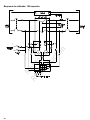
Wiring Diagram - 100 Amp.............................................14
Wiring Schematic - 100 Amp......................................... 15
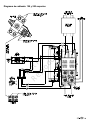
Wiring Diagram - 150 and 200 Amp.............................. 16
Wiring Schematic - 150 and 200 Amp........................... 17
Specifications......................................................................18
Specifications Chart - 100 and 150 Amp........................18
Specifications Chart - 200 Amp..................................... 18
Not for
Reproduction

3
Where to Find Us
You never have to look far to find support and service for
your equipment. There are many authorized service dealers
worldwide that provide quality service. You can also contact
Customer Service by phone at800-732-2989between 8:00
AM and 5:00 PM central time or click on Dealer Locator
at www.briggsandstratton.com, which provides a list of
authorized dealers.
For Future Reference
Please fill out the information below and keep with your
receipt. Have this information at hand if it becomes necessary
to contact your installer or authorized dealer regarding service
or repair of your equipment.
Date of Purchase: ________________________________
Dealer / Retailer: _________________________________
Dealer's / Retailer'sPhone Number: __________________
TRANSFER SWITCH:
Model Number: ____________________________
Model Revision: ____________________________
Serial Number: ____________________________
Important Safety Instructions
Every effort has been made to make sure that the information
in this manual is accurate and current. However, we reserve
the right to change, or improve the product and this document
without notification.
The manufacturer cannot possibly anticipate every possible
circumstance that can involve a hazard. The warnings in
this manual, and the tags and decals affixed to the unit are,
therefore, not all-inclusive. If you use a procedure, work
method or operating technique that the manufacturer does
not recommend, you must satisfy yourself that it is safe for
you and others. You must also make sure that the procedure,
work method or operating technique that you choose does not
render the equipment unsafe.
Safety Alert Symbol and Signal Words
The safety alert symbol identifies safety information
about hazards that can result in personal injury. A signal
word (DANGER,WARNING, orCAUTION) is used with
the alert symbol to indicate the likelihood and the potential
severity of injury. In addition, a hazard symbol may be used
to represent the type of hazard.
DANGERindicates a hazard which, if not
avoided,willresult in death or serious injury.
WARNINGindicates a hazard which, if not
avoided,couldresult in death or serious injury.
CAUTIONindicates a hazard which, if not
avoided,couldresult in minor or moderate injury.
NOTICEIndicates information considered important but not
hazard-related.
Symbols and Meanings
Symbol Meaning
Indicates a potential personal injury hazard.
Failure to obey warnings, instructions, installation and
operator's manual(s) could result in death or serious injury.
Generator and utility power could cause electric shock
resulting in death or serious injury.
Safety Messages
WARNING
This product contains lead and lead compounds,
known to the state of California to cause birth defects
or other reproductive harm. Wash your hands after
handling this product. Cancer and Reproductive Harm -
www.P65Warnings.ca.gov.
WARNING
Failure to read and obey the operator’s manual, all
warnings, and operating instructions could result in death or
serious injury.
WARNING
Hazardous Voltage -Installing low and high voltage
wire in same conduit could cause electric shock or burns,
resulting in death or serious injury.
• Do not run low and high voltage wire in the same
conduit unless the insulation rating on ALL wiring is
rated for 600V. See NFPA 70 for more information.
Not for
Reproduction

4
WARNING
Generator and utility voltage could cause electrical
shock or burn resulting in death or serious injury.
• Installation must be performed by a licensed
professional.
• Disconnect all sources of electricity before installing or
servicing equipment.
• Ground system before applying power.
WARNING
Generatorand utilityvoltage could cause electrical
shock or burn resulting in death or serious injury.
• DO NOT allow unqualified persons to operate or
servicethis equipment.
WARNING
Shock Hazard. Equipment contains high voltage
that could cause electrocution resulting in death or serious
injury.
• Testing must only be performed by qualified personnel.
NOTICE Improper treatment ofequipment could damage it
and shorten its life.
• Useequipmentonly for intended uses.
• If you have questions about intended use, contact your
authorized dealer.
• DO NOT exposeequipmentto excessive moisture,
dust, dirt, or corrosive vapors.
• Remain alert at all times while working on this
equipment. Never work on the equipment when you are
physically or mentally fatigued.
Not for
Reproduction

5
Installation
We sincerely appreciate your patronage and have made
significant effort to provide for a safe, streamlined and cost-
effective installation. Because each installation is unique,
it is not possible to know of and advise the trade of all
conceivable procedures and methods by which installation
could be achieved. It is not possible that we could know
of all possible hazards and/or the results of each method
or procedure. For these reasons, only current licensed
electrical professionals should attempt system installations.
Installations must strictly comply with all applicable codes,
industry standards and regulations. Your equipment is
supplied with this Installation and Operator’s Manual. This
document is important and should be retained by the owner
after the installation has been completed.
Installer Responsibilities
• Read and obey the safety instructions.
• Read and obey the instructions in this Installation and
Operation Manual.
• The installer may need to provide appropriate rated
contactors based on loads to be controlled.
• Installation must strictly comply with all applicable codes,
industry standards, laws, and regulations.
• Check federal, state and local codes and authority having
jurisdiction, for questions on installation.
• Make sure the generator is not overloaded with selected
loads.
• Load management could be necessary based on
approved load calculations and generator size.
• Speak to the owner about their load priority preferences
to decide on remote module priority settings.
• Speak to the owner about the Transfer Switch placement.
If you need more information about the transfer switch, call
800-732-2989, between 8:00 AM and 5:00 PM CT.
Owner Responsibilities
To help you make the correct choices and communicate
effectively with your installation contractor(s), read and
understand theOwner Orientationthat follows before you
contract or start your equipment installation.
• Read and obey the instructions in this Installation and
Operation Manual.
• Schedule regular maintenancefor your equipment to be
done by licensed electrical professionals.
For correct installation, contact the store where you
purchased your equipment, your dealer, or your utility power
provider. The equipment warranty is VOID unless the system
is installed by licensed electrical professionals.
Owner Orientation
The illustrations given are for typical circumstances and are
meant to familiarize you with the installation options available
with your system. Local codes, appearance, and distances
must be considered when negotiating with an installation
professional. As the distance from the existing electrical
service increases, compensation in wiring materials must
be allowed for. This is necessary to comply with local codes
and to overcome electrical voltage drops.These factors will
have a direct effect on the overall price of your equipment
installation.
Your installer must find local codes AND get the necessary
permits before the system is installed.
Equipment Description
The transfer switch is designed to transfer whole house
to standby power in the event of a primary power outage.
The load connects to the utility power (normal) or to home
standby power (generator). The generator controller monitors
utility and generator voltages, and automatically controls
the transfer switch board to connect load to the appropriate
source of power.
Only a licensed electrician should complete a home standby
installation. Service conduit and conductors can be wired
directly from the watt-hour meter to the transfer switch. A
separate service entrance disconnect and associated wiring
is not necessary when installed as specified by applicable
federal, state and local codes, standards andregulations.
Major components of the transfer switch are a 2 poleService
Disconnect Circuit Breaker, a 2 pole double throw transfer
switch, transfer switch board, fused utility terminals and
interconnecting wiring. All of these components are housed in
a NEMA3R enclosure that is appropriate for both indoor and
outdoor installations.
The transfer switch is solenoid-operated from utility or
generator inputs and contain suitable mechanical and
electrical interlock switches to eliminate the possibility of
connecting the utility service to the generator output. It has
ratings that can switch full utility power into the residence. A
manual override lever is provided for the transfer function.
The generator controller has active circuits that senses utility
and generator voltages. The generator controller controls
when the generator starts and when the transfer switch
transfers to utility or generator power. The status LEDs show
the position of the transfer switch contactor.
Delivery Inspection
Prevent damage from dropping, bumping, or collision with the
shipping carton.
After you openthe carton, carefully examine the transfer
switch components for any damage that could have occurred
duringshipment.
If loss or damage is noted at time of delivery, make sure that
the person(s) making delivery note all damage on the freight
bill and affix his signature under the consignor’s memo of loss
or damage. If loss or damage is noted after delivery, contact
the carrier for claim procedures. Missing or damaged parts
are not warrented.
Not for
Reproduction

6
Shipment contents:
• Automatic transfer switch
• Installation and Operator’s Manual
• Wireless Gateway and manual (optional)
To be supplied by the installer:
• Connecting wire and conduit
• Various specialty tools/equipment
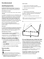
Mounting Guidelines
The transfer switch system circuitry is enclosed in a
NEMA Type3R enclosure suitable for indoor/outdoor use.
Guidelines for mounting the enclosure include:
• Install enclosure on a firm, strong support structure.
• The transfer switch enclosure must be installed with
minimum NEMA3R hardware for conduit connections.
• To prevent switch contact distortion, level and plumb the
enclosure. This can be done by putting washers between
the enclosure and the mounting surface.
• DO NOT install the transfer switch where too much
corrosive substances could fall onto the enclosure.
• Protect the switch at all times against excessive moisture,
dust, dirt, lint, construction grit and corrosivevapors
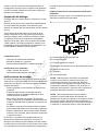
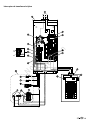
A typical automatic transfer switch installation is shown in
Figure1. It is best if the transfer switch is mounted near the
utilitywatt-hour meter, either inside or outside. Speak to the
owner about layout suggestions and changes before you start
the system installation process.
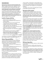
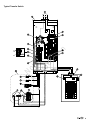
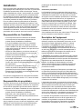
Typical Automatic Transfer Switch Installation
Refer to Figure1for a typical automatic transfer switch
installation.
1
(A) -Air Conditioner Disconnect
(B) - Branch Circuits
(C) - Main Distribution Panel
(D) - Transfer Switch with Service Disconnect
(E) - Watt-Hourmeter
(F) - Generator
(G) - Air Conditioner
NOTICE Before you drill conduit entry holes, or other
holes, protect the switch and electronics with a cover.
This prevents dirt and metal fragments from entering the
mechanical and electrical components. Failure to do so
could result in damage or malfunction of the switch. Wiring
to generator must be enclosed in conduit.
NOTICE Use a vacuum to clean any dirt or metal
shavings inside the transfer switch. Do not use a blower
or compressed air to clean the inside of the transfer switch
because debris may become lodged in the electrical and
mechanical components causing damage or malfunction.
Power Wiring Interconnections
NOTICE Incorrect installation could cause damage to the
circuit boards and shorten their life.If you install the circuit
boards in live circuits it will damage the board, which is not
included in the warranty. ALWAYS disconnect ALL sources
of power before you service the generator.
• Disconnect all power connections before you install
this equipment. Failure to do so could cause internal
damage to the board during electrical connections.
All wiring must be the correct gauge, correctly supported and
protected by conduit. All wiring must be done as specified
byfederal, state and local codes, standards and regulations.
Obey the wire type and torque specifications printed on the
terminal blocks, neutral/ground connectors, and installation
instructions.
WARNING
Generator and utility voltage could cause electrical
shock or burn resulting in death or serious injury.
• Installation must be performed by a licensed
professional.
• Disconnect all sources of electricity before installing or
servicing equipment.
• Ground system before applying power.
Use the installer supplied 600VAC or greater copper or
aluminum wire of a gauge that complies with the latest
version of the National Electric Code to complete the
connections between utility power, transfer switch, generator,
main distribution panel, and optional remote modules. Apply
the necessary correction factors and wire size calculations.
1. Set theGenerator Circuit Breakerto theOFFposition.
2. Set theGenerator ON/OFF Switch to theOFFposition.
3. Remove the 15 Amp fuse from the generator.
4. Disconnectthe utility power to the generator and transfer
switch.
Not for
Reproduction

7
5. Connect the utility service to the transfer switch’sService
Disconnect Circuit Breakerterminals that are labeled
“UTILITYCONNECTION."
6. Connect the utility service neutral to theTransfer Switch
Neutral Terminal.
7. Connect the main distribution panel feeder
conductors to the transfer switch terminalsthat are
labeled“LOADCONNECTION.”
8. Connect theNeutral Busto theTransfer Switch Neutral
Terminal.
9. Connect theGround Busto theTransfer Switch Ground
("GND") Terminal.
NOTICE Make sure that thegrounding electrode
conductor is connected and bonded as specified by federal,
state and local codes, standards and regulations.
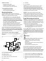
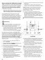
10. Connect the feeder conductors from transfer switch
“GENERATOR CONNECTION” terminals to generator
circuit breaker LINE1 and LINE2 terminals.Refer to
Figure2for the correct transfer switch connections.
2
11. Connect the conductor from the Transfer Switch Neutral
Terminalto the generator NEUTRAL terminal. Read the
generator control panel labeling for terminalidentification.
12. Connect the conductor from theTransfer Switch Ground
("GND") Terminalto theGenerator Ground Terminal.
NOTICE If specifically required by federal, state, or local
codes, make sure the generator grounding conductor is
connected.
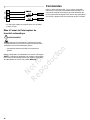
13. Use a minimum #14 AWG conductors, to connect the
transfer switch “UTILITY 240 VAC” terminals to the
generator’s “240 VAC” terminals through the two-pole
connector included with the generator.
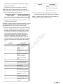
14. Use a minimum #18 AWG twisted pair copper or
aluminum conductors for GND and T/R and for +12VDC
a single #18 AWG. Refer to the table below for the
maximum wire length specified by the wire gauge sizes.
WARNING
Hazardous Voltage -Installing low and high voltage
wire in same conduit could cause electric shock or burns,
resulting in death or serious injury.
• Do not run low and high voltage wire in the same
conduit unless the insulation rating on ALL wiring is
rated for 600V. See NFPA 70 for more information.
Maximum Wire Length Wire Gauge
1 - 200 ft
(1 - 60 m)
18
201 - 300 ft
(61 - 91 m)
16
301 - 500 ft
(92 - 152 m)
14
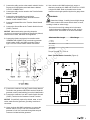
Torque TerminalJ7= 2.5 lb-in.
Basic Transfer Switch Controller(Figure3):
3
Not for
Reproduction

8
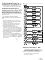
Generator Control Panel, GC1031(Figure4):
4
(A) Located at the generator (a Briggs &
Stratton
®
generator is shown)
(B) Located at the transfer switch
Generator Control Panel, Standard(Figure5):
5
(A) Located at the generator (a Briggs &
Stratton
®
generator is shown)
(B) Located at the transfer switch
NOTICE For this system to operate correctly, the
generator controller must have the correct hardware and
software version as specified in the table that follows.
Hardware
Revision or Higher
Software Revision
or Higher
E4 E1.00
15. Neutral is bonded to Ground with a green wire or a green
wire with a yellow stripe.
Note:Make sure that this Neutral to Ground bond is installed
as specified by all current NEC, state and local codes,
standards and regulations.
16. Tighten all wire connections and fasteners to the correct
torque. See the label inside the transfer switch enclosure
or the values listed in the remote module installation
instructions for the correct torque values.
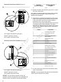
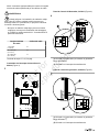
TheTypical Transfer Switchillustration that follows shows
a completed transfer switch installation. The actual
layout can vary. Make sure that the callouts in theTypical
Transfer Switchillustration agree with the components in
the list that follows:
Callout Component
A From Utility Watt-Hour Meter
B Transfer Switch Enclosure
C Terminal J7
D Transfer switch Relay Control
Module (TRCM)
E Transfer Switch Neutral
Terminal
F Neutral Bus
G Ground Bus
H Distribution Panel
J Utility 240 VAC to Generator
K Ten or Eight Pin Terminal Strip
L Two PinTerminal Strip
M Generator Circuit Breaker
N Generator
P Generator Neutral Terminal
R Generator Ground Terminal
S Transfer Switch Ground
Terminal
T Load Connection to Distribution
Panel
U Service Disconnect Circuit
Breaker
V Utility Connection
W Generator Connection
X Neutral to Ground bond
17. For the correct torque values refer to the decals located
at the Transfer Switch.
NOTICE The wires between the generator and the transfer
switch must be enclosed in the conduit.
Not for
Reproduction

9
Typical Transfer Switch
Not for
Reproduction

10
System Setup (for GC1031 Controller
and TRCM Board)
1. No setup is necessary for the GC1031 controller to
function with the TRCM board.
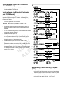
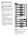
System Setup (for Standard Controller
and TRCM Board)
This is only applicable to Briggs & Strattongenerator
controller software version E1 or higher, hardware E4 or
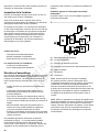
higher. For system setup, refer to the flowchart (Figure6) and
the steps that follow.
1. Go to the generator control panel.
NOTICE Make sure the generator controller is off.
2. Access the advanced menu screen settings. Refer to
theControl Panelsection in the Generator Operator's
Manual.
3. In the advanced menu screen, scroll to the transfer switch
settings as shown in Figure6.
4. Set the TRCM and push OK.
5. If the generator is installed in an area regularly subjected
to temperatures below 40°F (4°C), select a 50 second
warm up time at the advanced menu settings. The factory
default is set to a 20 second warm up.
6. Put the 15A ATO fuse into the fuse holder of the
generator controller.
7. Measure the voltage across the GND terminal and +12V
DC at the generator's electrical box. The voltage should
be approximately +12V DC. If there is no voltage,check
to make sure that the hardware revision of the control
panel is E4 or higher.
6
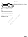
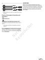
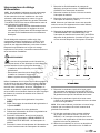
Supervisory Control Wiring (A-A) and
(B-B)
• A-A and B-B are NC contacts that are used as lockouts
when the transfer switch is switched to generator power.
Note:A-A and B-B are independent circuits.
• A-A and B-B are rated 120V AC, 1A (Figure7).
Not for
Reproduction

11
7
• A-A and B-B wire range 12 - 22 AWG. Torque 12 lb/in.
Test the Automatic Transfer Switch
WARNING
Shock Hazard. Equipment contains high voltage
that could cause electrocution resulting in death or serious
injury.
• Testing must only be performed by qualified personnel.
Turn theService Disconnect Circuit Breakerto
theOFFposition. The system’s automatic sequence will
initiate. To return to utility power, turn the Service Disconnect
Circuit Breaker to theONposition.
Controls
Other than a manual override lever, there are no operator
controls because this is an automatic transfer switch.
The manual override is to be used only by licensed
professionals.TogetInformation on the lever,call Technical
Service at 800-732-2989.
Not for
Reproduction

12
Operation
Normal Operation
Utility Fail
The generator senses when the utility voltage is below
70percent of nominal. The engine start sequence initiates
after a 6-second time delay.
Engine Warm-Up
This is the time delay for engine warm-up before transfer.
Transfer
The transfer from the utility to the generator supply occurs
after the voltage is above set levels. The generator control
board will send a transfer signal (12 VDC) to the TRCM
board. Then, the red LED will turn ON and the transfer switch
switches to generator power. The minimum engine operation
time is 5 minutes after transfer.
Utility Pickup
The voltage pickup level is 80 percent of the nominal voltage.
Re-transfer
Re-transfer from the generator to the utility power is
approximately 10 seconds after the utility voltage supply
is above pickup level and the minimum operation time is
completed.
Engine Cool Down
Standard controller - The engine will operate for 1 minute (60
seconds) after re-transfer.
GC1031 controller - The engine will operate for 5 minutes
(300 seconds) after re-transfer.
Set the Automatic Transfer Operation
To set the automatic transfer operation, complete the steps
that follow:
1. In the transfer switch, set theService Disconnect Circuit
Breakerto theONposition.
2. Set theGenerator Disconnect Circuit Breakerto
theONposition.
3. Install a 15 Amp fusein the generator.
4. Set thegenerator controller toAUTO.
Enclosure Door
WARNING
Generatorand utilityvoltage could cause electrical
shock or burn resulting in death or serious injury.
• DO NOT allow unqualified persons to operate or
servicethis equipment.
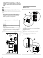
Open the Door
1. Open the transfer switch door.
2. Remove the two exterior thumb screws (A, Figure8).
3. Carefully lift off the door.
Close the Door
1. Push the door against the enclosure.
2. Put the tab on the enclosure into the slot on the door.
Note:The door can now rest on the tab (B, Figure,8) at the
bottom of the enclosure.
3. Install the thumb screws (A). Tighten them with your
hand.
NOTICE The enclosure door MUST be closed and
secured at all times except when the system is being
serviced.
8
When Calling for Assistance
You must have the Model Number and Serial Number from
each transfer switch or remote module ID label at hand if
it is necessary to contact a local service center regarding
service or repair. Obtain this information from the unit ID
labels located on or inside device. For convenience, record
the information in theFor Future Reference section at the
front of this manual.
To contact Briggs & Stratton call800-732-2989,between 8:00
AM and 5:00 PM CT.
Pre-Service Inspection
Before you service the system, examine all of the installation
carefully.
Not for
Reproduction

13
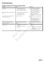
Troubleshooting
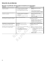
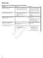
Troubleshooting the Automatic Transfer Switch
PROBLEM CAUSE CORRECTION
The automatic transfer switch does not transfer to
the generator.
1. The generator breaker is open.
2. The generator voltage is incorrect.
3. There is no transfer signal (12VDC).
1. Reset the generator circuit breaker.
2. Refer to theGenerator Manual.
3. Check for transfer signal (12VDC) at the
generator controller and TRCM
The Automatic transfer switch does not transfer to
utility.
1. TheService Disconnect Circuit Breakeris
open in the transfer switch.
2. The utility voltage is incorrect.
1. Reset theService Disconnect Circuit
Breakerin the transfer switch.
2. Wait for the utility voltage to come back
tonormal.
The generator continues to operate after the
switch transfers to utility power.
Engine cool down period. The engine will stop after the specified minutes
that follow:
• Standard controller: the engine will stop
after1 minute (60 seconds)
• GC1031 controller:the engine will stop
afterfive minutes (300 seconds).
The generator or supervised loads (air
conditioner, etc.) operate incorrectly when the
generator supplies power.
A-A or B-B contacts operate incorrectly.
They do not operate under generator power
(locked out).
Check A-A or B-B contacts for the correct
operation and/or check the control wiring to the
external load.
The generator continues to operate after utility
power comes back.
1. The minimum engine operation time has
notelapsed.
2. The fuse(s) in the transfer switch
isdefective.
1. Wait for the transfer switch to re-transfer to
utility power.
• Standard controller: wait 1 minute (60
seconds).
• GC1031 controller: wait five minutes
(300 seconds).
2. Contact an authorized servicecenter.
Not for
Reproduction

14
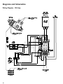
Diagrams and Schematics
Wiring Diagram - 100 Amp
Not for
Reproduction

15
Wiring Schematic - 100 Amp
Not for
Reproduction

16
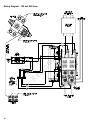
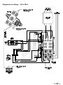
Wiring Diagram - 150 and 200 Amp
Not for
Reproduction

17
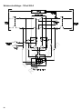
Wiring Schematic - 150 and 200 Amp
Not for
Reproduction

18
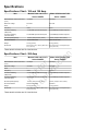
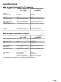
Specifications
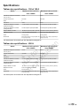
Specifications Chart - 100 and 150 Amp
Item Model 071210 and 071211 Model 071250 and 071251
Series 100SED Series 150SED
Rated Maximum Load Current 25°C
(77°F)
100 Amps 150 Amps
Rated AC Voltage 250 Volts 250 Volts
Poles 2 2
Frequency 60 Hz 60 Hz
Fault Current Rating
(Utility Side)
10,000 RMS Symmetrical Amperes 22,000RMS Symmetrical Amperes
Fault Current Rating
(Generator Side)
10,000 RMS Symmetrical Amperes 10,000RMS Symmetrical Amperes
Normal Operating Range -28.8°C (-20°F) to 40°C (104°F) -28.8°C (-20°F) to 40°C (104°F)
Enclosure Material Galvannealed Steel Galvannealed Steel
Weight 15.4 kg (34 lbs) 20.4 kg (45 lbs)
Dimensions 20.3 in (51.6 cm) x 14.5 in (36.8cm) x
7 in (17.8cm)
30 in (76.2cm) x 14.5 in (36.8cm) x
7.0 in (17.8cm)
These transfer switches are UL Listed devices.
Specifications Chart - 200 Amp
Item Model 071270 and 071271 Model 071273 and 071274
Series 200SED Series 200SED
Rated Maximum Load Current 25°C
(77°F)
200 Amps 200 Amps
Rated AC Voltage 250 Volts 250 Volts
Poles 2 2
Frequency 60 Hz 60 Hz
Fault Current Rating
(Utility Side)
22,000 RMS Symmetrical Amperes 22,000RMS Symmetrical Amperes
Fault Current Rating
(Generator Side)
10,000 RMS Symmetrical Amperes 10,000RMS Symmetrical Amperes
Normal Operating Range -28.8°C (-20°F) to 40°C (104°F) -28.8°C (-20°F) to 40°C (104°F)
Enclosure Material Galvannealed Steel Aluminum
Weight 20.4 kg (45 lbs) 10.4 kg (23 lbs)
Dimensions 30 in (76.2cm) x 14.5 in (36.8cm) x
7.0 in (17.8cm)
30 in (76.2cm) x 14.5 in (36.8cm) x
7.0 in (17.8cm)
These transfer switches are UL Listed devices.
Not for
Reproduction

19
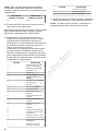
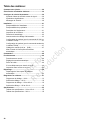
Índice de contenidos:
Dónde encontrarnos...........................................................20
Para futuras referencias.....................................................20
Instrucciones de seguridad importantes..........................20
Símbolo de alerta de seguridad y palabras de
señalización.................................................................... 20
Símbolos y significados..................................................20
Mensajes de seguridad.................................................. 20
Instalación............................................................................22
Responsabilidades del instalador...................................22
Responsabilidades del propietario................................. 22
Descripción del equipo...................................................22
Inspección de entrega....................................................23
Instrucciones de montaje............................................... 23
Interconexiones de cableado de energía....................... 24
Configuración del sistema (para el Controlador GC1031 y
la tarjeta del TRCM).......................................................28
Configuración del sistema (para el controlador estándar y
la tarjeta del TRCM).......................................................28
Cableado de control de supervisión (A-A) y (B-B)..........28
Pruebe el interruptor de transferencia automática......... 29
controles.............................................................................. 29
Funcionamiento...................................................................30
Funcionamiento normal.................................................. 30
Configurar la Operación de transferencia
automática...................................................................... 30
Puerta del gabinete........................................................ 30
Cuando llame para pedir ayuda.....................................30
Inspección previa al servicio.......................................... 31
Solución de problemas...................................................... 32
Solución de problemas del Interruptor de transferencia
automática...................................................................... 32
Diagramas y Esquemas..................................................... 33
Diagrama de cableado: 100 amperios........................... 33
Esquema de cableado: 100 amperios............................34
Diagrama de cableado: 150 y 200 amperios................. 35
Esquema de cableado: 150 y 200 amperios..................36
Especificaciones................................................................. 37
Tabla de especificaciones: 100 y 150 amperios............ 37
Tabla de especificaciones: 200 amperios...................... 37
Not for
Reproduction

20
Dónde encontrarnos
Nunca tendrá que buscar mucho para encontrar soporte y
servicio para su equipo. Hay muchos agentes de servicio
autorizados en todo el mundo que ofrecen un servicio de
calidad. También puede comunicarse con el Servicio de
atención al cliente por teléfono al 800-732-2989 entre las
8:00 a. m. y las 5:00 p. m., hora Central, o haga clic en el
Localizador de distribuidores en www.briggsandstratton.com,
que proporciona una lista de los distribuidores autorizados.
Para futuras referencias
Por favor, complete la siguiente información y guárdela con
su recibo. Tenga esta información a mano si es necesario
ponerse en contacto con su instalador o distribuidor
autorizado en relación con el servicio o la reparación de su
equipo.
Fecha de compra:________________________________
Distribuidor/Vendedor: _________________________________
Número de teléfono del Distribuidor/Vendedor:
__________________
INTERRUPTOR DE TRANSFERENCIA:
Número de modelo: ____________________________
Revisión del modelo: ____________________________
Número de serie: ____________________________
Instrucciones de seguridad
importantes
Se han hecho todos los esfuerzos para garantizar que la
información de este manual sea precisa y actualizada. Sin
embargo, nos reservamos el derecho de cambiar o mejorar el
producto y este documento sin previo aviso.
El fabricante no puede prever todas las circunstancias
posibles que pueden implicar un peligro. Las advertencias
de este manual, así como las etiquetas y calcomanías que
se han fijado a la unidad, no son, por lo tanto, exhaustivas.
Si utiliza un procedimiento, método de trabajo o técnica de
operación que el fabricante no recomiende, debe asegurarse
de que sea seguro para usted y para los demás. También
debe asegurarse de que el procedimiento, método de trabajo
o técnica operativa que elija no haga que el equipo sea
inseguro.
Símbolo de alerta de seguridad y
palabras de señalización
El símbolo de alerta de seguridad identifica
información de seguridad sobre peligros que pueden
provocar lesiones personales. Se usa una palabra de
señalización (PELIGRO,ADVERTENCIA oPRECAUCIÓN)
junto con el símbolo de alerta para indicar la probabilidad
y la gravedad potencial de las lesiones. Además, se puede
usar un símbolo de peligro para representar el tipo de
riesgo.
PELIGROindica un riesgo que, si no se
evita,ocasionarála muerte o lesiones graves.
ADVERTENCIAindica un riesgo que, si no se
evita,podríaocasionar la muerte o lesiones graves.
PRECAUCIÓNindica un riesgo que, si no se
evita,podríaocasionar lesiones leves o moderadas.
AVISO Indica información que se considera importante pero
que no está relacionada con un peligro.
Símbolos y significados
Símbolo Significado
Indica un posible riesgo para su integridad física.
No obedecer las advertencias, instrucciones ni los
manuales del operador y de instalación podría provocar
lesiones graves o la muerte.
El generador y la electricidad de la compañía eléctrica
podrían causar descargas eléctricas que podrían ocasionar
la muerte o lesiones graves.
Mensajes de seguridad
ADVERTENCIA
Este producto contiene plomo y compuestos de plomo que,
de acuerdo con el estado de California, ocasionan defectos
de nacimiento u otros daños reproductivos. Lávese las
manos luego de manipular este producto. Cáncer y daño
reproductivo: www.P65Warnings.ca.gov.
ADVERTENCIA
No leer y no seguir las instrucciones de operación,
todas las advertencias y el manual del operador podría
ocasionar lesiones graves o la muerte.
Not for
Reproduction
La page est en cours de chargement...
La page est en cours de chargement...
La page est en cours de chargement...
La page est en cours de chargement...
La page est en cours de chargement...
La page est en cours de chargement...
La page est en cours de chargement...
La page est en cours de chargement...
La page est en cours de chargement...
La page est en cours de chargement...
La page est en cours de chargement...
La page est en cours de chargement...
La page est en cours de chargement...
La page est en cours de chargement...
La page est en cours de chargement...
La page est en cours de chargement...
La page est en cours de chargement...
La page est en cours de chargement...
La page est en cours de chargement...
La page est en cours de chargement...
La page est en cours de chargement...
La page est en cours de chargement...
La page est en cours de chargement...
La page est en cours de chargement...
La page est en cours de chargement...
La page est en cours de chargement...
La page est en cours de chargement...
La page est en cours de chargement...
La page est en cours de chargement...
La page est en cours de chargement...
La page est en cours de chargement...
La page est en cours de chargement...
La page est en cours de chargement...
La page est en cours de chargement...
La page est en cours de chargement...
La page est en cours de chargement...
-
 1
1
-
 2
2
-
 3
3
-
 4
4
-
 5
5
-
 6
6
-
 7
7
-
 8
8
-
 9
9
-
 10
10
-
 11
11
-
 12
12
-
 13
13
-
 14
14
-
 15
15
-
 16
16
-
 17
17
-
 18
18
-
 19
19
-
 20
20
-
 21
21
-
 22
22
-
 23
23
-
 24
24
-
 25
25
-
 26
26
-
 27
27
-
 28
28
-
 29
29
-
 30
30
-
 31
31
-
 32
32
-
 33
33
-
 34
34
-
 35
35
-
 36
36
-
 37
37
-
 38
38
-
 39
39
-
 40
40
-
 41
41
-
 42
42
-
 43
43
-
 44
44
-
 45
45
-
 46
46
-
 47
47
-
 48
48
-
 49
49
-
 50
50
-
 51
51
-
 52
52
-
 53
53
-
 54
54
-
 55
55
-
 56
56


Simplicity 071274-00 Guide d'installation
- Catégorie
- Groupes électrogènes
- Taper
- Guide d'installation