
LAARS Heating Systems
Page 2
SECTION 1.
General Information
WARNING
Mascot II units must be installed in accordance
with the procedures detailed in this manual, or the
LAARS Heating Systems warranty will be voided.
The installation must conform to the requirements
of the local jurisdiction having authority, and, in the
United States, to the latest edition of the National Fuel
Gas Code, ANSI Z223.1/NFPA54. In Canada, the
installation must conform to the latest edition of CSA
B149.1 Natural Gas and Propane Gas Installation
Code, and/or local codes. Where required by the
authority having jurisdiction, the installation of Mascot
II boilers must conform to the Standard for Controls
and Safety Devices for Automatically Fired Boilers,
ANSI/ASME CSD-1. Any modications to the boiler,
its gas controls, or wiring may void the warranty.
If eld conditions require modications, consult
the factory representative before initiating such
modications.
1.1 Introduction
This manual provides information necessary for
the installation, operation, and maintenance of LAARS
Heating Systems Mascot II appliances. Read it carefully
before installation.
All application and installation procedures
should be reviewed completely before proceeding
with the installation. Consult the LAARS Heating
Systems factory, or local factory representative, with
any problems or questions regarding this equipment.
Experience has shown that most operating problems are
caused by improper installation.
Mascot II is protected against over pressurization.
A pressure relief valve is included with each Mascot II.
The PRV should be installed prior to lling the system.
Refer to Figures 1 and 2 for PRV locations.
IMPORTANT: The inlet gas pressure to the appliance
must not exceed 13” W.C. (3.2kPa).
All installations must be made in accordance with
1) American National Standard Z223.1/NFPA54-Latest
Edition “National Fuel Gas Code” or 2) CSA B149.1
“Natural Gas and Propane Installation Code” and with
the requirement of the local utility or other authorities
having jurisdiction. Such applicable requirements take
precedence over the general instructions contained
herein.
All electrical wiring is to be done in accordance
with the local codes, or in the absence of local codes,
with: 1) The National Electrical Code ANSI/NFPA No.
70-latest Edition, or 2) CSA STD. C22.1 “Canadian
Electrical Code - Part 1”. This appliance must be
electrically grounded in accordance with these codes.
1.2 ModelIdentication
Consult the rating plate on the unit. The following
information describes the model number structure.
(1-2) Model Series Designation
L M = Mascot II
(3) Usage
H = Modulating Boiler
C = Combination Boiler and Water Heater
(4-6) Size
1 2 5 = 125,000 BTU/hr input
(7) Fuel
N = Natural Gas
P = LP Gas
(8) Altitude
A = 0-10,000 Feet
(9) Revision
1 = First version
(10) Options Code
X = No Options
(11) Pump Options
X = No Pump
(12) Regulatory Designation
B = Internal Use
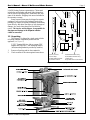
1.3 Appliance Overview
See Figure 2.
1.4 Warranty
LAARS Heating Systems’ Mascot II appliances
are covered by a limited warranty. The owner should
complete the warranty registration at www.Laars.com.
All warranty claims must be made to an authorized
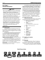
Model Nomenclature
1 2 3 4 5 6 7 8 9 10 11
L M 1 2 5 A 1 X X
SERIES
L M
USAGE
H - HYDRONIC
C - COMBI
UNIT
SIZE
MBTU/h
1 2 5
FUEL
N - NATURAL
P - PROPANE
ALTITUDE
A - 0-10,000 FEET
REVISION
1 - FIRST
OPTIONS
X - NONE
PUMP
X - NONE
REG DESIGNATION
B - INTERNAL USE
B
12
H2338601-
Addendum to 1239 Install/Operating Instruction Manual
Addendum - Nov 16th, 2012 H2338601-
Model Sizes Part No. Doc. # Page .
Mascot ll 125 H2338600- Doc. 1239 2
Pg 2 Model Nomenclature
An additional number has been added to the
Model Nomenclature for product tracking
purposes.
Page Change

User’s Manual Document 1239
H2338600-
WARNING
If the information in this manual is not
followed exactly, a fire or explosion may
result causing property damage, personal
injury or loss of life.
Do not store or use gasoline or other
flammable vapors and liquids in the vicinity
of this or any other appliance.
WHAT TO DO IF YOU SMELL GAS
• Do not try to light any appliance.
• Do not touch any electrical switch; do not
use any phone in your building.
• Immediately call your gas supplier from a
nearby phone. Follow the gas supplier's
instructions.
• If you cannot reach your gas supplier, call
the fire department.
Installation and service must be performed by
a qualified installer, service agency, or gas
supplier.
FOR YOUR SAFETY: This product must be installed and serviced by a professional service technician,
qualified in hot water boiler and heater installation and maintenance. Improper installation and/or operation
could create carbon monoxide gas in flue gases which could cause serious injury, property damage, or
death. Improper installation and/or operation will void the warranty.
AVERTISSEMENT
Assurez-vous de bien suivres les instructions
données dans cette notice pour réduire au
minimum le risque d’incendie ou d’explosion ou
pour éviter tout dommage matériel, toute
blessure ou la mort.
Ne pas entreposer ni utiliser d’essence ni
d’autres vapeurs ou liquides inflammables dans
le voisinage de cet appareil ou de tout autre
appareil.
QUE FAIRE SI VOUS SENTEZ UNE ODEUR DE GAZ:
• Ne pas tenter d’allumer d’appareils.
• Ne touchez à aucun interrupteur. Ne pas vous
servir des téléphones dansle bâtiment où vous
vous trouvez.
• Appelez immédiatement votre fournisseur de
gaz depuis un voisin. Suivez les instructions
du fournisseur.
• Si vous ne pouvez rejoindre le fournisseur de
gaz, appelez le sservice des incendies.
L’installation et l’entretien doivent être assurés par
un installateur ou un service d’entretien qualifié ou
par le fournisseur de gaz.
User’s Information for
Mascot
®
II
Modulating Boiler
Model LMH
125 MBTU/h
Combination
Boiler and Water Heater
Model LMC
125 MBTU/h

LAARS Heating Systems
Page 2
SECTION 1.
General Information
WARNING
Mascot II units must be installed in accordance with
the procedures detailed in this manual, or the LAARS
Heating Systems warranty will be voided. The
installation must conform to the requirements of the
local jurisdiction having authority, and, in the United
States, to the latest edition of the National Fuel Gas
Code, ANSI Z223.1/NFPA54. In Canada, the
installation must conform to the latest edition of CSA
B149.1 Natural Gas and Propane Gas Installation
Code, and/or local codes. Where required by the
authority having jurisdiction, the installation of Mascot
II boilers must conform to the Standard for Controls
and Safety Devices for Automatically Fired Boilers,
ANSI/ASME CSD-1. Any modifications to the boiler,
its gas controls, or wiring may void the warranty. If
field conditions require modifications, consult the
factory representative before initiating such
modifications.
1.1 Introduction
This manual provides information necessary for
the installation, operation, and maintenance of LAARS
Heating Systems Mascot II appliances. Read it carefully
before installation.
All application and installation procedures should
be reviewed completely before proceeding with the
installation. Consult the LAARS Heating Systems
factory, or local factory representative, with any
problems or questions regarding this equipment.
Experience has shown that most operating problems are
caused by improper installation.
Mascot II is protected against over pressurization.
A pressure relief valve is included with each Mascot II.
The PRV should be installed prior to filling the system.
Refer to Figures 1 and 2 for PRV locations.
IMPORTANT: The inlet gas pressure to the appliance
must not exceed 13" W.C. (3.2kPa).
All installations must be made in accordance with
1) American National Standard Z223.1/NFPA54-Latest
Edition “National Fuel Gas Code” or 2) CSA B149.1
“Natural Gas and Propane Installation Code” and with
the requirement of the local utility or other authorities
having jurisdiction. Such applicable requirements take
precedence over the general instructions contained herein.
All electrical wiring is to be done in accordance
with the local codes, or in the absence of local codes,
with: 1) The National Electrical Code ANSI/NFPA No.
70-latest Edition, or 2) CSA STD. C22.1 “Canadian
Electrical Code - Part 1”. This appliance must be
electrically grounded in accordance with these codes.
1.2 Model Identification
Consult the rating plate on the unit. The following
information describes the model number structure.
(1-2) Model Series Designation
L M = Mascot II
(3) Usage
H = Modulating Boiler
C = Combination Boiler and Water Heater
(4-6) Size
1 2 5 = 125,000 BTU/hr input
(7) Fuel
N = Natural Gas
P = LP Gas
(8) Altitude
A = 0-10,000 Feet
(9) Revision
1 = First version
(10) Options Code
X = No Options
(11) Pump Options
X = No Pump
1.3 Appliance Overview
See Figure 2.
1.4 Warranty
LAARS Heating Systems’ Mascot II appliances
are covered by a limited warranty. The owner should
complete the warranty registration at www.Laars.com.
All warranty claims must be made to an authorized
Model Nomenclature
12 3 456 7 8 9 10 11
LM 125 A 1 X X
SERIES
L M
USAGE
H - HYDRONIC
C - COMBI
UNIT
SIZE
MBTU/h
1 2 5
FUEL
N - NATURAL
P - PROPANE
ALTITUDE
A - 0-10,000 FEET
REVISION
1 - FIRST
OPTIONS
X - NONE
PUMP
X - NONE

User’s Manual - Mascot II Boilers and Water Heaters
Page 3
LAARS Heating Systems representative. Claims must
include the serial number and model (this information
can be found on the rating plate), installation date, and
name of the installer. Shipping costs are not included in
the warranty coverage.
Some accessory items may be shipped in separate
packages. Verify receipt of all packages listed on the
packing slip. Inspect everything for damage immediately
upon delivery, and advise the carrier of any shortages or
damage. Any such claims should be filed with the
carrier. The carrier, not the shipper, is responsible for
shortages and damage to the shipment whether
visible or concealed.
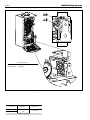
1.5 Unpacking
The Mascot II is shipped in a single crate with the
following standard components packed with the
appliance (see Figure 1):
2" PVC Terminal Kit (tee, elbow, screens, PRV
adapter and 30psi PRV), wall mounting bracket
(bolts/mounting hardware provided by installer).
1. Remove all packing and tie-down materials.
2. Check contents of the carton against items shown.
Figure 1. Contents of Shipping Package.
1) PRV, 30 PSI 5) Exhaust terminal assy
2) PRV Pipe 6) Air intake terminal assy
3) Wall attach bracket 7) Ball valve
4) Outdoor sensor 8) System sensor (not shown)
Figure 2. Location of Components.

LAARS Heating Systems
Page 4
SECTION 2.
Operating Instructions
2.1 Filling the Boiler System
1. Ensure the system is fully connected. Close all
bleeding devices and open make-up water valve.
Allow system to fill slowly.
2. Move manual lever on 3-way valve actuator to
"open" position, allowing air to purge from boiler
loop. Valve is normally in DHW position until
there is a call for Central Heat via "T-T" contacts.
If make-up water pump is employed, adjust
pressure switch on pumping system to provide a
minimum of 12 psi (81.8 kPa) at the highest point
in the heating loop.
3. If a water pressure regulator is provided on the
make-up water line, adjust the pressure regulator to
provide at least 12 psi (81.8 kPa) at the highest
point in the heating loop.
4. Open bleeding devices on all radiation units at the
high points in the piping throughout the system,
unless automatic air bleeders are provided at such
points.
Note that there is an air bleed located on the left
side of Mascot II, on top of the jacket.
5. Cycle the boiler pump on and off 10 times, 10
seconds on and 10 seconds off to remove all air
from the heat exchanger. Then run system and
appliance pump for a minimum of 30 minutes with
the gas shut off.
6. Using manual lever located on left side of 3-way
valve actuator, move from "open" position back to
closed position repeatedly. This process forces air
out of the internal DHW loop.
WARNING
Failure to remove all air from the heat exchanger could
lead to property damage, severe injury or death.
7. Recheck all air bleeders as described in Step 4.
8. Start up boiler according to the procedure in this
manual. Operate the entire system, including the
pump, boiler, and radiation units for one (1) hour.
9. Shut down the entire system and vent all radiation
units and high points in the system piping, as
described in Step 4.
10. Close make-up water valve and check strainer in
pressure reducing valve for sediment or debris
from the make-up water line. Reopen make-up
water valve.
11. Check gauge for correct water pressure and also
check water level in the system. If the height
indicated above the boiler insures that water is at
the highest point in the circulating loop, then the
system is ready for operation.
12. Refer to local codes and the make-up water valve
manufacturer’s instructions as to whether the
make-up water valve should be left open or closed.
13. After placing the unit in operation, the ignition
system safety shutoff device must be tested.
First, shut off the manual gas valve, and call the
unit for heat. Main gas terminals will be energized,
attempting to light, for four (4) seconds, and then
will de-energize. The unit will go into lockout after
the required number of trial for ignition periods.
Second, turn the power off, press the manual reset
button on the boiler control, or the user display,
open the manual gas valve and allow the unit to
light. While the unit is operating, close the manual
gas valve and ensure that power to the main gas
valve has been cut.
14. Within three (3) days of start-up, recheck all air
bleeders and the expansion tank as described in
Steps 4 and 8 above.
Important Note: The installer is responsible for
identifying to the owner/operator the location of all
emergency shutoff devices.
WARNING
Do not use this appliance if any part has been under
water. Immediately call a qualified service technician
to inspect the appliance
and to replace any part of the control system and any
gas control that may have been
under water.
2.2 Operating the Burner and Set Up
Initial setup must be checked before the unit is put
in operation. Problems such as failure to start, rough
ignition, strong exhaust odors, etc. can be due to
improper setup. Damage to the boiler resulting from
improper setup is not covered by the limited warranty.
2.2.1 Burner Operation
REQUIRED TOOLS: differential pressure gauge
capable of reading negative 0.01 inches W.C. (0.002kPa),
screw drivers, and combustion analyzer.
1. Using this manual, make sure the installation is
complete and in full compliance with the
instructions and all local codes.
2. Determine that the appliance and system are filled
with water and all air has been bled from both.
Open all valves.
3. Observe all warnings on the Operating Instructions
label and turn on gas and electrical power to
appliance.
4. Mascot II will enter the start sequence. Blower and
pump will energize for pre-purge, then the ignition
sequence starts. After all safety devices are
verified, the gas valve opens. If ignition doesn’t
occur, turn off the Mascot II, check that there is

User’s Manual - Mascot II Boilers and Water Heaters
Page 5
proper gas supply. Wait 5 minutes and start the
unit again.
5. Turn Mascot II on.
6. After placing the appliance in operation, the
Burner Safety Shutoff Device must be tested:
(a) Close gas shutoff valve with burner operating.
(b) Flame will go out and blower will continue to
run for the post purge cycle. One or three
additional attempts to light will follow including
pre-purge, ignitor on, valve/flame on and post
purge. Ignition will not occur as the gas is off.
The ignition control will lockout.
(c) Open gas shutoff valve. Reset the boiler
control by pressing the
RESET button on the
control or on the display. Restart the
appliance. The ignition sequence will start
again and the burner will start. The appliance
will return to its previous mode of operation.
Caution
Should any odor of gas be detected, or if the gas
burner does not appear to be functioning in a normal
manner, CLOSE MAIN SHUTOFF VALVE. Do not
shut off switch. Contact your heating contractor, gas
company, or factory representative.
2.2.2 Boiler Setup and Adjustment
1. Measure the CO
2
in the flue products at high fire.
The Mascot II can be forced to high fire to allow
for easier setup. The CO
2
readings should be
between the values shown in Table 2. If the CO
2
is
not within the range shown, adjustments may be
made. To adjust the high fire CO
2
, locate the high fire
adjuster screw according to the appropriate figure.
Slowly make adjustments in 1/16 of a revolution
increments until the CO
2
is within the range
identified.
2. Measure the CO
2
/O
2
in the flue products at low
fire. Mascot II can be forced to low fire to allow
for easier setup. CO
2
readings should be between
the values shown in Table 2. If the CO
2
is not
within the range shown, adjustments may be made.
To adjust the low fire CO
2
, locate the low fire
adjuster screw according to the appropriate figure.
Slowly make adjustments in 1/16 of a revolution
increments until the CO
2
is within the range
identified (see Figure 3).
3. Repeat steps 1 and 2 to confirm that the CO
2
ranges are within the required ranges. Adjust if
necessary.
4. If any of the measurements cannot be adjusted
to the specified ranges or the CO levels are
above 150ppm when adjusted please consult the
factory for further information.
WARNING
Improper adjustment may lead to poor combustion
quality, increasing the amount of carbon monoxide
produced. Excessive carbon monoxide levels may
lead to personal injury or death.
2.3 Shutting Down Mascot II
1. Turn off the main electrical disconnect switch.
2. Close all manual gas valves.
3. If freezing is anticipated, drain Mascot II and be
sure to also protect building piping from freezing.
All water must be removed from heat exchanger
and condensate trap or else damage from freezing
may occur.
This step to be performed by a qualified service person.
2.4 To Restart Mascot II
If drained, follow Section 2.1 in this manual for
proper filling and purging.
1. Turn off the main electrical disconnect switch.
2. Close all manual gas valves.
3. WAIT FIVE (5) MINUTES.
4. Set the aquastat or thermostat to its lowest setting.
5. Open all manual gas valves.
6. Reset all safety switches (pressure switch, manual
reset high limit, etc.).
7. Set the temperature controller to the desired
temperature setting and switch on electrical power.
8. Burner will go through a prepurge period and
ignitor warm-up period, followed by ignition.
MENU ITEM FUNCTION RANGE DEFAULT
Outlet water Displays the current outlet 55-190°F 120°F
temperature water temperature & allows
the setpoint to be adjusted
Inlet water Displays the current inlet — —
temperature water temperature
Delta T Displays the current — —
temperature rise across
the heat exchanger
Stack Displays the current stack — —
temperature temperature
Outdoor Displays the current outdoor — —
temperature air temperature
Firing Rate Displays an indicator of the — —
current firing rate based
upon fan RPM. The actual
firing rate may vary.
Table 1. User Mode Menu Structure.

LAARS Heating Systems
Page 6
GAS TYPE HIGH FIRE, CO
2
LOW FIRE, CO
2
Natural 9.0
0% offset
Propane 10.0
Table 2. CO
2
Range.
Figure 3. Adjustment Screws and Settings for CO
2
.
ADJUSTMENT RANGE:
High Fire CO
2
: 9.0–8.8% Nat; 10.0–9.8% LP
Low Fire CO
2
: 0% offset

User’s Manual - Mascot II Boilers and Water Heaters
Page 7
SECTION 3.
Gas Conversion
3.1 Gas Conversion
Mascot II units can be converted from natural to
propane gas or from propane to natural gas easily in the
field. Please contact the Laars factory for specific
information regarding the gas conversion of an
appliance. If a gas conversion is performed, the unit
must be identified with the appropriate gas labels and a
conversion sticker to allow technicians performing
maintenance in the future to properly identify the gas
type of the appliance. These stickers are included with
the boiler during shipment.
WARNING
This conversion shall be installed by a qualified
service agency in accordance with the manufacturer's
instructions and all applicable codes and
requirements of the authority having jurisdiction. If
the information in these instructions is not followed
exactly, a fire, an explosion or production of carbon
monoxide may result causing property damage,
personal injury or loss of life. The qualified service
agency is responsible for the proper and complete
installation of this kit. The installation is not proper
and complete until the operation of the converted
appliance is checked as specified in the
manufacturer's instruction supplied with the kit.
AVERTISSEMENT
Ce conversion doit être installé par un organisme de
service conformément aux instructions du fabricant et
tous les codes et les exigences de l'autorité
compétente. Si les informations contenues dans ces
instructions n'est pas suivi à la lettre, un incendie, une
explosion ou de la production de monoxyde de
carbone mais résultat causant des dommages
matériels, des blessures ou des pertes de vie. Le
service est responsable pour la bonne et complète
l'installation de ce kit. L'installation n'est pas correcte
et complète jusqu'à ce que le fonctionnement de
l'appareil converti est vérifiée comme spécifié dans le
manuel d'instruction fourni avec le kit.
Conversion to LP Gas Instructions:
1. Install "Propane Gas" sticker over the "Natural
Gas" sticker where the gas supply line enters the
appliance.
2. Fill out gas conversion sticker and install adjacent
to the Rating Plate sticker behind the center door
panel.
3. Confirm that the gas supply is propane.
4. Start boiler per lighting procedure shown on inside
front cover or side of appliance.
WARNING
Serious injury or death could occur if
CO
2
levels are not adjusted properly.
5. With a combustion analyzer, check CO
2
and CO
levels at both maximum and minimum input. Input
rating will remain unchanged.
6. Remove lower cover to access gas valve and adjust
as needed. Begin by adjusting the maximum input
CO
2
then continue by adjusting the minimum input
CO
2
. Any high fire adjustment may affect low fire
settings. Screws for adjustment are shown in
Figure 3.
7. Reinstall front cover.

H2338600-
800.900.9276 • Fax 800.559.1583 (Customer Service, Service Advisors)
20 Industrial Way, Rochester, NH 03867 • 603.335.6300 • Fax 603.335.3355 (Applications Engineering)
1869 Sismet Road, Mississauga, Ontario, Canada L4W 1W8 • 905.238.0100 • Fax 905.366.0130
www.Laars.com Litho in U.S.A. © Laars Heating Systems 1008 Document 1239
®
-
 1
1
-
 2
2
-
 3
3
-
 4
4
-
 5
5
-
 6
6
-
 7
7
-
 8
8
-
 9
9


Laars LMC Series Manuel utilisateur
- Taper
- Manuel utilisateur
- Ce manuel convient également à
dans d''autres langues
- English: Laars LMC Series User manual