Acesonic AM-170 Manuel utilisateur
- Catégorie
- Équipement musical supplémentaire
- Taper
- Manuel utilisateur

1
AM-170
250-Watt Professional Mixing Amplier
®
User Manual
NOTE: To ensure this system works safely and to its fullest potential, please read the User Manual before
use, and keep it handy for future reference. See important safety information on Pages 7-8.
ank you for purchasing Acesonic’s AM-170 250-
Watt (@ 4 Ohms) Professional Mixing Amplier.
Acesonic takes pride in providing its customers with
only the most advanced and highest quality products
on the market. With proper care and use you will
get many years of satisfying use from your Acesonic
product.
Be sure to keep original packaging in case re-shipping
is required for returns or repairs.
First Things First
Before using your AM-170, take a few simple steps:
• Check to see that your local power outlets supply
the correct voltage for the AC input.
• Do not open the device as there are no user-
serviceable parts inside. For repairs, contact the
local distributor, an authorized service center or
Acesonic’s U.S. headquarters.
• Care and cleaning directions are included in this
User Manual, but preventive measures are good
common sense. Do not use the device in areas that
are wet or prone to dampness. Always allow su-
cient room around the device to provide sucient
air ow for cooling.
• When the device will not be used for a long period
of time, disconnect the power plug from the wall,
as well as the back of the unit, and remove all con-
necting cables for proper storage.
Table of Contents
First ings First .................................................1
System Components ............................................2
Product Features ..................................................2
Initial Setup Considerations ................................2
Front Panel Operations .......................................2
Back Panel Operations ........................................3
Remote Control Operations ................................4
Care & Maintenance ...........................................4
Troubleshooting ..................................................5
Connecting the AM-170 .....................................6
FCC Advisory, Safety Warnings & Safe Use .......7
Company Contact Information ...........................8

2
System Components
Your Acesonic AM-170 unit is designed for years of
enjoyment. Please take a moment to review the fol-
lowing instructions for its proper use and care.
Included Accessories
Your AM-170 includes the following items:
• 1 AM-170 Mixing Amplier
• 1 Remote control
• 1 AC power adapter cord
• User’s Manual, Warranty Card
If you are is missing any of these items, contact your
Acesonic dealer at once.
Product Features
e AM-170 allows you to connect mixer, player or
other audio devices directly to its stereo RCA audio
inputs for instant sound. You also have great exibility
in output choices.
• 80+80W @ 8 Ohms maximum output
• 125+125W @ 4 Ohms equivalent output
• Four A/V inputs selector
• Microphone volume control
• Microphone bass, middle and treble control
• Microphone echo repeat and delay control
• Music bass, middle and music treble control
• Music balance control
• Five 1/4" microphone inputs: 3 front, 2 rear
• Music eect bypass switch
• Dynamic sound enhancer - Enhance a full range
of frequencies for both music and vocals
• Fully digital, color LCD display
• Record line output and subwoofer output
• One pair banana speaker outputs
Initial Setup Considerations
is basic setup guide provides simple, step-by-step
instructions for setting up your AM-170 system,
along with a complete diagram of the back panel con-
nections and switches. Audio systems vary, so you may
need additional and/or longer cables, adaptors, etc.,
to connect your system in the way(s) you want. For
any questions, please contact your dealer or Acesonic
technical support.
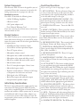
Front Panel Operations
Refer to the Figure A at the top of page 3 (right).
1. KEY CONTROL - e line of buttons allows you
to raise or lower the key by six (6) semi-tones. e
center button is the original (natural) key, and at is
to the left while sharp is to the right.
2. MASTER MICROPHONE VOLUME – is
dial controls the master volume for all three micro-
phone inputs. Turning clockwise raises the volume.
3. POWER ON/OFF button - Turns the AM-170
on or o.
4. MUSIC CONTROLS - ese control the volume,
balance and tone (Treble, Mid and Bass) of the music
output from all input sources.
5. MICROPHONE TONE - ese controls adjust
the Treble, Mid and Bass tone for all microphones
that are in use.
6. MICROPHONE ECHO – ese controls adjust
the Repeat, Volume and Delay settings for Echo.
7. INDIVIDUAL MICROPHONE VOLUME –
ese controls adjust the Volume independently for
Mic 1, Mic 2 and Mic 3.
8. MICROPHONE INPUTS – ree 1/4" input
jacks for microphones.
9. MASTER MUSIC VOLUME – is control ad-
justs the Master Volume for music coming from any
of the sources.
10. AUTO SELECT – is button enables the unit
to scan and detect the signal automatically (BGM,
AUX, DVD and CDG). When the signal is detected
and identied, the scanning will stop and you will see
the input source indicator light conrming the selec-
tion (see Item #11, below).
11. INPUT SELECTION – is button selects the
input source in manual mode. You can switch input
among BGM, AUX, DVD and CDG. e selection
will be reected by the appropriate signal indicator.
12. 3D SOUND AND MUTE – is button selects
3D Sound, for enhanced music and vocal audio, as
well as Mute. e button will toggle from o to these
two functions, then back to o on a third press.
13. MPX – is button will select among Stereo (no
light) and Left/Right, which will be indicated by the
appropriate indicator light (L or R) as shown on the
panel above and to the right of the button.
14. IR REMOTE RECEIVER – e IR Receiver

3
that takes commands from the Remote Control is
located here. Do not obstruct line of sight access to
this portion of the display during use.
15. INFORMATION DISPLAY WINDOW – is
color display shows a range of information, as well as
the frequency levels of the program material.
1
2
3
4 5 6 7 8
9
12
13 10
14
15
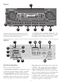
Back Panel Operations
Refer to the Figure B directly above.
1. MICROPHONE INPUTS – ese two 1/4" jacks
are alternate, back-panel inputs for Mic 1 and Mic 2.
Use front panel knobs to control volume and tone.
2. VIDEO INPUTS – is line of Video inputs that
take RCA connectors from the various source inputs.
Each Video input is associated with the Left and
Right Audio inputs directly below (see Item #3, below).
3. AUDIO – ese Audio inputs, Left and Right, ac-
cept source inputs (BGM, AUX, DVD and CDG).
4. PRE – ese RCA jacks allow you to send the sig-
nal to an external signal processor via the Ouput jacks,
and receive the processed signal back via Inputs.
5. VIDEO OUT – is RCA output jack works with
the Audio outs below it (see Item #6, below) to supply
a composite signal to an external device.
2
3
4
5
6
1
10 11
12
9
13
7 8
11
Figure B
Figure A

4
6. AUDIO OUT – RCA jacks for Audio out.
7. REC OUT AND LINE OUT – ese RCA jacks
are for sending Audio to external recording units or
other devices.
8. SUB AND MIC OUTPUTS – e SUB RCA
jacks send Audio signals of appropriate frequency
to subwoofers. e MIC jacks send High and Low
signals to other audio devices.
9. SPEAKER CONNECTIONS – e Left and
Right pairs of posts connect to your speakers.
10. SOURCE INPUTS – e jacks in this location
accept inputs from BGM, AUX, DVD and CDG.
11. S-VIDEO OUT – is output jack sends an
S-Video signal for input to TVs and TV-connected
devices that use the format.
12. VOLTAGE SELECT – is switch selects be-
tween 115 and 230 volts for AC power.
13. AC INPUT – is is where the power cord con-
nects to the back of the AM-170.
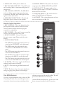
Remote Control Operations
1. KEY CONTROL – e b and # keys adjust the
pitch up and down by semitones, while the center
selection (natural symbol) returns the program
material to its original key.
2. MIC VOLUME – e + and - buttons control the
Volume of the microphone(s) being used.
3. MUSIC VOLUME – Increase or decrease
the music master output Volume with the + and -
buttons.
4. SOURCE SELECTIONS :
• e AUX button selects the external source con-
nected to the AUX INPUT on the back panel.
• e BGM button selects the external source
connected to the BGM INPUT on the back
panel.
• e DVD button selects the external source con-
nected to the DVD INPUT.
• e AUTO button enables the automatic input
detection on the AM-170 to select the source.
• e CDG button selects the external source con-
nected to the CDG INPUT on the back panel.
5. 3D SOUND – is button toggles the 3D Sound
enhanced audio between o and on.
6. MUTE – is button toggles Mute between o
and on.
7. MPX – is button selects the various Audio mix
settings, toggling among Stereo, Left and Right.
1
2
3
4
6
7
5
Care & Maintenance
Use only a slightly dampened cloth to clean the AM-
170, and dry o with a clean towel. Keep the unit in
an area free of excessive moisture, and always allow
sucient room around the unit for airow. is will
prevent the AM-170 from overheating.
As with all audio and electronics gear, do not use the
device except as described in these instructions.

5
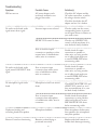
Symptom
Will not turn on
No audio can be heard, audio
signal meter shows signal
No audio can be heard, audio
signal, meter DOES NOT show
signal
No microphone signal can be
heard
Unpleasant howling and
screeching heard from speakers
Remote Control not functioning
Possible Cause
AC power adapter cord is
incorrectly attached or not
plugged into outlet
Incorrect input source selected
MUSIC VOL control is down
Poor or incorrect output
connection to speakers or other
external units, or bad/defective
cables, wires or connectors
Poor or incorrect input
connection from audio source
unit, or bad/defective cables,
wires or connectors
Microphone controls are turned
down
Poor or incorrect input
connection from microphone,
or bad/defective cables, wires or
connectors
Microphone feedback
Batteries are dead, dying or
positioned incorrectly
Solution(s)
Check the AC adapter and the
AC outlet connections, as well as
the voltage selection switch
Check the fuse below the AC
adapter and see if it is broken
Check to make sure the correct
corresponding button is pressed
on the input selector in relation to
your audio source
Check to see if MUSIC VOL
control is all the way down; if so,
turn the knob slowly clockwise
Double check all output
connections to speakers or
other units.; try using another
set of cables/cords; make sure
to turn POWER OFF before
reconnecting cables
Double check all output
connections to speakers or
other units.; try using another
set of cables/cords; make sure
to turn POWER OFF before
reconnecting cables
Check MIC MASTER VOL and
all MIC VOL controls to see if
they are turned down; if so, turn
the knob slowly clockwise
Double check all microphone
connections; try using another
cable/cord; make sure to turn
MIC MASTER VOL down
before reconnecting cables
Place microphones farther away
from speakers; face microphones
away from speakers
Replace with fresh batteries or
double check battery positioning
Troubleshooting

6
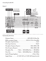
Technical Specications
Maximum Output ................................................80W+80W @ 8 Ohm Max
RMS (continuous) Output .............................125W+125 W @ 4 Ohm RMS
Microphone Input Sensitivity ...........................................................<20mV
Music Input Sensitivity ....................................................................300mV
Microphone Frequency Response .................................. 20Hz–20KHz/ 3dB
Music Frequency Response ........................................... 20Hz–20KHz/ 3dB
Microphone EQ .................Treble: +/- 5dB (10KHz), Bass: +/- 5dB (100Hz)
Music EQ ...........................Treble: +/- 5dB (10KHz), Bass: +/- 5dB (100Hz)
Speaker Wattage Impedance ................................................ 4 Ohm–8 Ohm
Supply Voltage .................AC 110V-120V or AC 220V-240V (manual switch)
Connecting the AM-170
Figure C

7
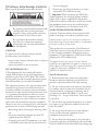
FCC Advisory, Safety Warnings & Safe Use
Mises en garde, precautions et procedures de sûreté
e lightning-with-arrowhead symbol inside
a triangle alerts the user that potentially
dangerous voltage in the product enclosure
may constitute a risk of electric shock.
e exclamation point within a triangle
alerts the user to important operating,
maintenance, and servicing information in
this User Manual.
CAUTION
To reduce the risk of electrical shocks, re and
possible injuries, you should not
• remove screws, buttons, antennae, jacks or any part
of the enclosure; or
• expose the product to rain or moisture.
FCC ADVISORY (U.S.A.)
1. is equipment has been tested and found to
comply with the limits for a Class B digital device,
pursuant to part 15 of the FCC Rules. ese limits
are designed to provide reasonable protection against
harmful interference in a residential installation.
is equipment generates, uses and can radiate radio
frequency energy and, if not installed and used in
accordance with the instructions, may cause harmful
interference to radio communications. However, there
is no guarantee that interference will not occur in a
particular installation. If this equipment does cause
harmful interference to radio or television reception,
which can be determined by turning the equipment
o and on, the user is encouraged to try correcting the
problem by one or more of the following measures:
• Reorienting and/or relocating the receiving anten-
nae
• Increasing the distance between the radio/TV
equipment and the AM-170
• Connecting the radio/TV equipment to an outlet
on a dierent circuit than the one into which the
receiver is plugged
• If necessary, consulting the dealer or an experi-
enced radio/TV technician for help
2. Important: When connecting the AM-170 to
audio equipment, use only high-quality, shielded
cables such as what is supplied with this product.
Follow all installation instructions and do not modify
the equipment in any way, as this could void your
FCC authorization to use the device in the U.S.
FOR CANADA/POUR LE CANADA
Caution: To prevent electric shock, match the wide
blade of the plug to the wide slot, and fully insert.
Attention: Pour eviter les chocs electriques, introduire la
lame la plus large de la che dans la borne correspondante
de la prise et pousser jusquau fond.
is product does not exceed the Class B limits for
radio noise emissions from digital devices as set out
in the Canadian standard for interference-causing
equipment (“Digital Apparatus, ICES-003” from the
Department of Communications).
Cet appareil numerique respecte les limites de bruits
radio electriques applicables aux appareils numeriques de
Classe B prescrites dans la normesur le materiel brouilleur
(“Appareils Numeriques, NMB-003” edictee par le
Ministre des Communications).
Safe Use Instructions
1. Read and follow these instructions, keep them
handy for reference, familiarize yourself with the
product’s operation and heed all safety warnings.
2. Do not use this product near water, on wet surfaces
or in places where moisture may accumulate. Do not
expose the device to dripping or splashing, and do
not place items lled with liquids – such as vases,
beverages, etc. – on top of the device. Clean only with
a dry cloth.
3. Do not block any ventilation openings or set device
on carpets or rugs. Maintain sucient room on all
sides for airow.
4. Do not position the device on or near radiators,
stoves or other electrical equipment (such as
ampliers) that produce heat.
5. Do not defeat the safety purpose of a polarized or
grounding-type plug. A polarized plug has two blades
with one wider than the other, while a grounding-type

AM-170 250-Watt Professional Mixing
Amplier
One (1) Year Manufacturer Warranty &
Lifetime Technical Support
Designed in U.S.A.
Technical Support: (626) 820-0645
E-mail: techsuppor[email protected]
Web site: www.acesonic.com
Acesonic USA, Inc.
161 S. 8th Avenue
City of Industry
CA 91746-3208
U.S.A.
© 2010 Acesonic USA, Inc. • All rights reserved
AM-170
250-Watt Professional Mixing Amplier
®
plug has two blades and one prong. e wide blade
and the prong are safety features. If the provided plug
does not t into your outlet, consult an electrician for
replacement of the obsolete outlet.
6. Protect the power cord from being walked on or
pinched, particularly where it is plugged in to an
electrical socket and the point where it exits from the
rear of the device.
7. Only use the attachments and accessories specied
by the manufacturer.
8. Use only with a cart, stand, tripod, bracket or table
specied by the manufacturer or sold with the device.
When using a cart, use caution when moving the cart.
9. Unplug the product during lightning storms or
when it will not be used for long periods of time.
10. Refer all servicing to qualied service personnel.
Servicing is required when the unit has been damaged
in any way, such as when the power-supply cord or
plug is damaged, liquids have been spilled or objects
introduced into the enclosure, the device has been
exposed to rain or moisture, the product does not
operate normally or it has been dropped.
11. Never push objects of any kind into this product,
through jacks or other openings, as they may contact
dangerous voltage points or short-circuit components,
thus causing re or electrical shock.
12. is product should be operated only from the
type of power source indicated on the product label
and in this User Manual. If you are not sure of the
type of power supplied to your home, consult your
product dealer or local utility.
13. An outside antenna system should not be located
in close proximity to overhead power lines, or other
electric light or power circuits, or where it can fall
into such power lines or circuits. When installing an
outside antenna system, be extremely careful not to
touch such power lines or circuits, as contact with
them could be fatal.
14. Do not overload wall outlets or extension cord
as this can increase the risk of re, power outages or
electrical shock.
15. When replacement parts are required, be sure the
service technician has used replacement parts specied
by the manufacturer or with the same characteristics
as the original part. Unauthorized substitutions may
result in re, electric shock or other hazards.
16. Following any servicing or repair of this product,
ask the service technician to perform the appropriate
safety checks to ensure the product is in proper
operating condition.
17. e product should not be mounted to a wall or
ceiling except as recommended by the manufacturer,
with a mounting accessory recommended by the
manufacturer.
18. If your product is not operating correctly or
exhibits a marked change in performance, and you
are unable to restore normal operation by following
procedures in this User Manual, do not attempt to
service it yourself. Opening the enclosure may expose
you to dangerous voltage or other hazards. Refer all
servicing to qualied service personnel.
-
 1
1
-
 2
2
-
 3
3
-
 4
4
-
 5
5
-
 6
6
-
 7
7
-
 8
8


Acesonic AM-170 Manuel utilisateur
- Catégorie
- Équipement musical supplémentaire
- Taper
- Manuel utilisateur
dans d''autres langues
- English: Acesonic AM-170 User manual