TOA A-800D Series Digital Mixer/Amplifier Manuel utilisateur
- Catégorie
- Matériel musical
- Taper
- Manuel utilisateur

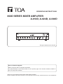
OPERATING INSTRUCTIONS
Thank you for purchasing TOA’s 800D Series Mixer Amplier.
Please carefully follow the instructions in this manual to ensure long, trouble-free use of your equipment.
A-812D, A-824D, A-848D
800D SERIES MIXER AMPLIFIER
The gure represents the A-812D.
Note on Firmware Upgrade
Before using the device, upgrade the rmware.
The latest rmware can be downloaded from the product page of the A-812D, A-824D, A-848D on
the TOA Corporation website.

2
TABLE OF CONTENTS
1. IMPORTANT SAFETY INSTRUCTIONS
........................................... 3
2. SAFETY PRECAUTIONS ............................................................................ 4
3. GENERAL DESCRIPTION .......................................................................... 6
4. FEATURES ............................................................................................................ 6
5. HANDLING PRECAUTIONS ...................................................................... 6
6. INSTALLATION PRECAUTIONS ............................................................. 7
7. THE DUCKER FUNCTION AND
THE PRIORITY BROADCAST FUNCTION ...................................... 7
8. NOMENCLATURE AND FUNCTIONS ................................................. 8
Front ............................................................................................................................. 8
Rear ............................................................................................................................. 9
9. CONNECTIONS ............................................................................................... 12
9.1. Speaker Connection ........................................................................................... 12
9.2. Input Terminal Connections and Settings ......................................................... 13
9.3. Connecting to the Remote Master Volume Control Terminal ............................. 15
9.4. Connecting to the Power Remote Control Output Terminal ............................... 15
9.5. Connecting to the Emergency Control Output Terminal ................................... 16
9.6. Connecting to the Control Input Terminal .......................................................... 16
9.7. Connecting the External Equipment
between the Pre-amplifier Output and the Power Amplifier ................................ 17
9.8. Removable Terminal Plug Connection ............................................................... 18
10. SETTINGS ......................................................................................................... 19
10.1. Chime Tone Setting .......................................................................................... 19
10.2. Module Setting ................................................................................................. 19
11. DUCKER DEPTH ADJUSTMENT ....................................................... 20
12. VOLUME ADJUSTMENT ......................................................................... 20
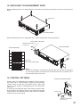
13. INSTALLING TO AN EQUIPMENT RACK .................................... 21
14. CONTROL SETTINGS ............................................................................. 21
15. PRIORITY BROADCAST FUNCTION .............................................. 22
15.1. Priority Broadcast ............................................................................................ 22
15.2. Priority Broadcast Mode ................................................................................... 22
15.3. Emergency Broadcast ...................................................................................... 23
15.4. Normal Broadcast ............................................................................................. 23
15.5. Relationship between the Priority/Emergency Broadcasts and
the Power On/Off State ..................................................................................... 23
15.6. Factory Default Settings ................................................................................... 24
16. SETTINGS ON THE BROWSER ......................................................... 25
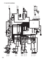
17. BLOCK DIAGRAM ....................................................................................... 26
18. SPECIFICATIONS ........................................................................................ 27
Accessories .............................................................................................................. 28
Optional product ....................................................................................................... 28

3
INSTRUCTIONS ESSENTIELLES POUR LA SÉCURITÉ
• Lire ces instructions.
• Conserver ces instructions pour référence ultérieure.
• Respecter tous les avertissements.
• Suivre toutes les instructions.
• Ne pas utiliser cet appareil à proximité d'eau.
• Nettoyer uniquement à l'aide d'un chiffon sec.
• Ne pas obstruer les orices de ventilation. Installer conformément aux instructions du fabricant.
• Ne pas installer à proximité de sources de chaleur telles que des radiateurs, des registres thermiques, des
chaudières ou d'autres appareils (notamment des amplicateurs) produisant de la chaleur.
• Ne pas contourner la fonction de sécurité de la che polarisée ou de mise à la terre. Une che polarisée est
équipée de deux broches, dont l'une est plus large que l'autre. Une che de mise à la terre est équipée de
deux broches et d'une troisième pour la mise à la terre. Cette dernière, la plus large, est prévue à des ns de
sécurité. Si la che fournie ne peut être insérée dans la prise électrique souhaitée, consulter un électricien
pour faire remplacer cette dernière.
• Protéger le cordon d'alimentation pour éviter qu'il ne soit piétiné ou pincé, notamment au niveau des ches,
des prises de courant ou de son point de sortie de l'appareil.
• Utiliser uniquement les accessoires spéciés par le fabricant.
• Utiliser uniquement avec le chariot, support, trépied, la patte de montage ou la table spéciés
par le fabricant ou vendus avec l'appareil. En cas d'utilisation d'un chariot, manipuler la
combinaison chariot/appareil pour éviter les blessures dues à un renversement.
• Débrancher cet appareil pendant les orages ainsi que lorsqu'il reste inutilisé pendant une période prolongée.
• La maintenance de l'appareil doit être conée à un technicien après-vente qualié. Une maintenance s'avère
nécessaire si l'appareil est endommagé (au niveau du cordon d'alimentation ou de la che), a été mouillé
par un liquide, un objet est tombé à l'intérieur, s'il a été exposé à la pluie ou l'humidité, s'il ne fonctionne pas
normalement ou s'il est tombé.
1. IMPORTANT SAFETY INSTRUCTIONS
• Read these instructions.
• Keep these instructions.
• Heed all warnings.
• Follow all instructions.
• Do not use this apparatus near water.
• Clean only with dry cloth.
• Do not block any ventilation openings. Install in accordance with the manufacture’s instructions.
• Do not install near any heat sources such as radiators, heat registers, stoves, or other apparatus (including
amplifiers) that produce heat.
• Do not defeat the safety purpose of the polarized or grounding-type plug. A polarized plug has two blades
with one wider than the other. A grounding type plug has two blades and a third grounding prong. The wide
blade or the third prong are provided for your safety. If the provided plug does not fit into your outlet, consult
an electrician for replacement of the obsolete outlet.
• Protect the power cord from being walked on or pinched particularly at plugs, convenience receptacles, and
the point where they exit from the apparatus.
• Only use attachments/accessories specified by the manufacturer.
• Use only with the cart, stand, tripod, bracket, or table specified by the manufacturer, or
sold with the apparatus. When a cart is used, use caution when moving the cart/apparatus
combination to avoid injury from tip-over.
• Unplug this apparatus during lightning storms or when unused for long periods of time.
• Refer all servicing to qualified service personnel. Servicing is required when the apparatus has been damaged
in any way, such as power-supply cord or plug is damaged, liquid has been spilled or objects have fallen into
the apparatus, the apparatus has been exposed to rain or moisture, does not operate normally, or has been
dropped.

4
When Installing the Unit
• Do not expose the unit to rain or an environment
where it may be splashed by water or other liquids,
as doing so may result in re or electric shock.
• Use the unit only with the voltage specied on
the unit. Using a voltage higher than that which is
specied may result in re or electric shock.
• Do not cut, kink, otherwise damage nor modify
the power supply cord. In addition, avoid using the
power cord in close proximity to heaters, and never
place heavy objects -- including the unit itself -- on
the power cord, as doing so may result in re or
electric shock.
• Be sure to ground to the safety ground (earth)
terminal to avoid electric shock. Never ground to a
gas pipe as a catastrophic disaster may result.
• Avoid installing or mounting the unit in unstable
locations, such as on a rickety table or a slanted
surface. Doing so may result in the unit falling down,
causing personal injury and/or property damage.
• Since the unit is designed for indoor use, do not
install it outdoors. If installed outdoors, the aging of
parts causes the unit to fall off, resulting in personal
injury. Also, when it gets wet with rain, there is a
danger of electric shock.
• The terminals marked with the symbol are
hazardous live.
The external wiring to these terminals requires
installation by an instructed person.
When the Unit is in Use
• Should the following irregularity be found during
use, immediately switch off the power, disconnect
the power supply plug from the AC outlet and
contact your nearest TOA dealer. Make no further
attempt to operate the unit in this condition as this
may cause re or electric shock.
· If you detect smoke or a strange smell coming
from the unit.
· If water or any metallic object gets into the unit
· If the unit falls, or the unit case breaks
· If the power supply cord is damaged (exposure of
the core, disconnection, etc.)
· If it is malfunctioning (no tone sounds.)
• To prevent a fire or electric shock, never open nor
remove the unit case as there are high voltage
components inside the unit. Refer all servicing to
your nearest TOA dealer.
• No objects lled with liquids, such as vases, shall
be placed on the unit. If they accidentally spill into
the unit, this may cause a re or electric shock.
• Do not insert nor drop metallic objects or ammable
materials in the ventilation slots of the unit’s cover,
as this may result in re or electric shock.
• Do not touch a power supply plug during thunder
and lightning, as this may result in electric shock.
When Installing the Unit
• Never plug in nor remove the power supply plug
with wet hands, as doing so may cause electric
shock.
• When unplugging the power supply cord, be sure to
grasp the power supply plug; never pull on the cord
itself. Operating the unit with a damaged power
supply cord may cause a re or electric shock.
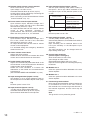
2. SAFETY PRECAUTIONS
• Before installation or use, be sure to carefully read all the instructions in this section for correct and safe
operation.
• Be sure to follow all the precautionary instructions in this section, which contain important warnings and/or
cautions regarding safety.
• After reading, keep this manual handy for future reference.
Safety Symbol and Message Conventions
Safety symbols and messages described below are used in this manual to prevent bodily injury and property
damage which could result from mishandling. Before operating your product, read this manual rst and
understand the safety symbols and messages so you are thoroughly aware of the potential safety hazards.
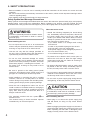
Indicates a potentially hazardous situation which,
if mishandled, could result in death or serious
personal injury.
WARNING
Indicates a potentially hazardous situation which,
if mishandled, could result in moderate or minor
personal injury, and/or property damage.
CAUTION

5
• When moving the unit, be sure to remove its power
supply cord from the wall outlet. Moving the unit
with the power cord connected to the outlet may
cause damage to the power cord, resulting in re or
electric shock. When removing the power cord, be
sure to hold its plug to pull.
• Do not block the ventilation slots in the unit’s cover.
Doing so may cause heat to build up inside the
unit and result in re. Also, periodically clean the
ventilation slots of dust.
• Avoid installing the unit in humid or dusty locations,
in locations exposed to the direct sunlight, near the
heaters, or in locations generating sooty smoke
or steam as doing otherwise may result in re or
electric shock.
When the Unit is in Use
• To avoid electric shocks, be sure to switch off the
unit’s power when connecting speakers.
• Be sure to follow the instructions below when rack-
mounting the unit. Failure to do so may cause a re
or personal injury.
· Install the equipment rack on a stable, hard oor.
Fix it with anchor bolts or take other arrangements
to prevent it from falling down.
· When connecting the unit’s power cord to an AC
outlet, use the AC outlet with current capacity
allowable to the unit.
· Rack-mounting screws are not supplied with the
unit. Prepare them that are appropriate for the
equipment rack.
• Do not place heavy objects on the unit as this may
cause it to fall or break which may result in personal
injury and/or property damage. In addition, the object
itself may fall off and cause injury and/or damage.
• Make sure that the volume control is set to minimum
position before power is switched on. Loud noise
produced at high volume when power is switched
on can impair hearing.
• Do not operate the unit for an extended period of
time with the sound distorting. Doing so may cause
the connected speakers to heat, resulting in a re.
• Contact your TOA dealer as to the cleaning. If dust is
allowed to accumulate in the unit over a long period
of time, a re or damage to the unit may result.
• If dust accumulates on the power supply plug or in the
wall AC outlet, a re may result. Clean it periodically.
In addition, insert the plug in the wall outlet securely.
• Switch off the power, and unplug the power supply
plug from the AC outlet for safety purposes when
cleaning or leaving the unit unused for 10 days or
more. Doing otherwise may cause a re or electric
shock.
ATTENTION
L'appareil ne doit pas être exposé aux éclaboussures ou écoulements et tous objets remplis de liquide, tels que
vases, ne doivent pas être sur l'appareil.
• The socket-outlet shall be installed near the equipment and the plug (disconnecting device) shall be
easily accessible.
• The apparatus shall be connected to a mains socket outlet with a protective earthing connection.
L'éclair accompagné d'un symbole
représentant une pointe de èche à
l'intérieur d'un triangle équilatéral avertit
l'utilisateur de la présence d'une "tension
dangereuse" à l'intérieur de l'enceinte du
téléviseur, dont la magnitude peut être
sufsante pour constituer un risque de
choc électrique pour les personnes.
The lightning flash with arrowhead
symbol, within an equilateral triangle, is
intended to alert the user to the presence
of uninsulated "dangerous voltage" within
the product's enclosure that may be of
sufficient magnitude to constitute a risk of
electric shock to persons.
The exclamation point within an
equilateral triangle is intended to
alert the user to the presence of
important operating and maintenance
(servicing) instructions in the literature
accompanying the appliance.
Le point d'exclamation à l'intérieur d'un
triangle équilatéral avertit l'utilisateur
de l'existence d'instructions d'utilisation
et d'entretien (réparation) dans la
documentation fournie avec l'appareil.

6
3. GENERAL DESCRIPTION
TOA's 800D Series mixer amplier is a PA amplier equipped with 4 microphone inputs, 2 auxiliary inputs, and
2 slots dedicated to the 900 Series modules. It employs a PFC circuit.
It also features the following functions: Volume control function, Priority function, Chime function, and Remote
conrmation function.
In addition, it is equipped with a 2-channel input BUS of AUDIO and DUCK, and the signal processing function.
The 800D Series mixer amplier is ideal for paging announcement and BGM applications in schools, ofces,
and super markets.
4. FEATURES
• 3 kinds of power amplifier outputs: 120 W (A-812D), 240 W (A-824D), and 480 W (A-848D)
• Lightweight owing to the built-in digital power amplifier unit
• Emergency broadcast and priority broadcast activated by way of the control input (contact)
• Voice detection function that allows the priority broadcast to be activated by voice
• Priority setting function
• Remote conrmation function that allows you to conrm the unit’s status through the web browser using a PC
• Switchable speaker output ("4 Ω" or "70 V line")
• Module slots provided for mounting up to 2 units of 900 Series modules
• Electronically-balanced 4 microphone inputs (MIC 1 to MIC 4) with Input setting switches
• Fine sound adjustment possible by connecting a signal processor like an equalizer between the pre-amplifier
output and the power amplifier input
• Bass and treble tone control knobs
• Output level meter
• Master volume control knob to simultaneously adjust all input levels
• Remotely controllable master volume
• Built-in chime unit (1-note chime, 2-note chime, and ascending 4-note chime)
• Equipped with the following signal processing functions:
Dynamic feedback lters, Equalizer (3 points), Gate, Software volume, Limiter, and Ducker
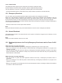
5. HANDLING PRECAUTIONS
• In this system, settings and control of the unit are performed on a PC via LAN (Local area network). It is not
possible to perform them via the Internet.
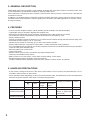
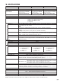
• Some operations differ depending on this unit’s power ON/OFF state. The table below shows the relationship
between the power ON/OFF state and the corresponding operation.
Power state LED lighting state Normal broadcast Priority broadcast/
Emergency broadcast
Web
access
CPU
RUN
From
Speaker
output
From
Recording
output
Not energized Unlit Unlit Disabled Disabled Disabled Disabled
Energized
(Power turned OFF)
Unlit Lit Disabled Disabled Occasionally possible
( Power is temporarily
turned ON.)
Enabled
Energized
(Power turned ON)
Lit Lit Enabled Enabled Enabled Enabled

7
7. THE DUCKER FUNCTION AND THE PRIORITY BROADCAST FUNCTION
This unit is provided with Ducker function and Priority broadcast function that decrease the output level of other
broadcasts while a specic broadcast is being made.
A Ducker function refers to the function to place a priority order between the audio signal groups divided into 2
groups. Use this function to make a simple usage such as to decrease the BGM level when making microphone
announcement while the BGM broadcast is in progress.
For the details of the Ducker function, refer to "DUCKER DEPTH ADJUSTMENT" on p. 20.
A Priority broadcast function is the function to assign one of 8 priority levels to each broadcast content. Use this
function to make a complicated usage compared with the Ducker function such as to select the audio signal to
mute.
For the details of the Priority broadcast function, refer to "PRIORITY BROADCAST FUNCTION" on p. 22.
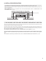
6. INSTALLATION PRECAUTIONS
• The supplied power supply cord is designed for exclusive use with the unit. Never use it with other equipment.
• Install the unit in a well-ventilated environment so that temperature inside the unit will not rise.
• When installing the unit on the desk, keep the unit over 10 cm (3.94") away from objects that may obstruct air
ow as shown below.
• When installing the unit in an equipment rack, mount perforated panels. Refer to "INSTALLING TO AN
EQUIPMENT RACK" on p. 21.
Over 10 cm (3.94")
Over 10 cm (3.94") Over 10 cm (3.94")
A-812D/824D/848D

8
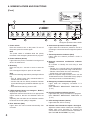
1. Power switch
Press this switch to turn on the power. To turn off
the power, press this switch again.
Note
The power switch is disabled while the priority
broadcast or the emergency broadcast is in progress.
2. Power indicator (Green)
Lights when the power is switched on and goes off
when it is switched off.
3. Reset key
Press this key for 1 second or more to reset the
unit.
Use a ne-tipped object to press in this switch.
Note
Perform the following steps before pressing the Reset
key.
•
Turn all volume knobs fully counterclockwise to
minimize the volume value.
•
Conrm that both the Priority broadcast indicator
(9) and the Emergency broadcast indicator (10) are
unlit.
•
Press the Power switch (1) to turn it OFF.
4. LED level meter (Green x 3, Orange x 1, Red x 1)
Displays the output level.
Adjust each volume control knob for an appropriate
output sound so that the red indicator does not
light.
Operating the unit while the red indicator remains
lit causes the sound quality to degrade.
5. Error indicator (Red)
Lights when the unit’s internal abnormality has
occurred.
6. Overcurrent protection indicator (Red)
Lights while the overcurrent protection circuit is
operating if overcurrent ows through the speaker
output.
7. Thermal protection indicator (Red)
Lights while the thermal protection circuit is
operating.
8.Network connection conrmation indicator
(Green)
An indicator to identify the unit using a web
browser.
• Flashes for 5 seconds when the identication
conrmation is performed using a web browser.
• Flashes 3 times when the unit is started up.
• Lights when in the manual mode.
( See the separate setup manual, which can be
downloaded from the TOA DATA Library (https://
www.toa-products.com/international/).)
9. Emergency broadcast indicator (Red)
Lights while the emergency broadcast is in
progress.
( See "PRIORITY BROADCAST FUNCTION" on
p. 22.)
10. Priority broadcast indicator (Green)
Lights while the priority broadcast is in progress.
( See "PRIORITY BROADCAST FUNCTION" on
p. 22.)
11. CPU running indicator (Green)
Lights while the CPU is running.
12. Volume control knobs for Inputs 1 through 6
Adjust the volume values of the Inputs 1 through 6.
Rotate each knob clockwise to increase the
volume value and counterclockwise to decrease it.
(See "VOLUME ADJUSTMENT" on p. 20.)
1
2
3
4
14
15
12 13
16
7
11
8
9
10
5
6
8. NOMENCLATURE AND FUNCTIONS
[Front]
The gure represents the A-812D.

9
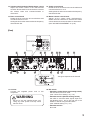
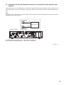
[Rear]
31
3026
25
27 28 29
32 4039
17 18
24
33 34 38
19
2120
22 23
35
36
37
17. AC inlet
Connect the supplied power cord to this
receptacle.
Be sure to use the supplied power cord.
Using any other power cord may cause
electric shock.
WARNING
18 . D IP switch
• Switches 1 and 2 (Chime tone setting switch)
Set the chime tone to be used.
(See "Chime Tone Setting" on p. 19.)
• Switches 3 and 4 (Module setting switch)
Set which to send the audio signals input from
the Module slots 1 and 2 (30 and 29) to the
AUDIO or DUCK using the DIP switch.
( See "Module Setting" on p. 19.)
• Switches 5 and 6
Not used.
13. Volume control knobs for Module inputs 1 and 2
Adjust the volume values of the rear-mounted
modules. Rotate each knob clockwise to increase
the volume value and counterclockwise to
decrease it.
14. Bass control knob
Rotate the knob clockwise to boost the bass and
counterclockwise to cut it.
Setting the knob at the center makes the frequency
characteristic at.
15. Treble control knob
Rotate the knob clockwise to boost the treble and
counterclockwise to cut it.
Setting the knob at the center makes the frequency
characteristic at.
16. Master volume control knob
Adjusts all the volume levels simultaneously.
Rotate the knob clockwise to increase the whole
volume level and counterclockwise to decrease it.
( See "VOLUME ADJUSTMENT" on p. 20.)
The gure represents the A-812D.

10
19. Remote master volume control terminal
Short-circuit current: 10 mA or less,
open voltage : 35 V DC or less,
removable terminal block (3.50 mm, 4 pins)
Sound volume can be adjusted by connecting the
10 kΩ B-taper potentiometer.
( See "Connecting to the Remote Master Volume
Control Terminal" on p. 15.)
20. Power remote control output terminal
Open collector output, withstand voltage: 30 V
DC or less, current: 25 mA or less, removable
terminal block (3.50 mm, 4 pins)
An output terminal that can be used for remote
control of other equipment. Operates in
synchronization with the unit’s power ON/OFF.
When the unit’s power is on, it is activated.
21. Emergency control output terminal
Open collector output, withstand voltage: 30 V
DC or less, current: 25 mA or less, removable
terminal block (3.50 mm, 4 pins)
An output terminal that can be used for remote
control of other equipment.
It is activated during the emergency broadcast
made from the unit.
22. Chime volume control knob
Adjusts the chime volume.
Rotate the knob clockwise to increase the chime
volume and counterclockwise to decrease it.
23. Ducker depth control knob
Adjusts the automatically attenuated level of the
sound volume on the DUCK while the broadcast
is being made using the AUDIO.
Rotate the knob clockwise to increase the
attenuation on the DUCK and counterclockwise
to decrease it.
(
See "DUCKER DEPTH ADJUSTMENT" on p. 20.)
24. Input setting switches (Inputs 3 and 4)
Set whether or not to supply phantom power to
the microphones connected to Inputs 3 and 4 (25).
Tip
Phantom power is a 24 V DC.
25. Input terminals (Inputs 3 and 4)
–60 dB
*, 600 Ω, electronically-balanced,
removable terminal block (3.81 mm, 3 pins)
Input terminals dedicated for microphones
26. Input setting switches (Inputs 1 and 2)
Set the input sensitivity level (LINE or MIC) of
the Inputs 1 and 2 (27). When switched to the
microphone input, set the phantom power to ON
or OFF.
Switch position
Input specication at the
time of setting
MIC PHANTOM ON –60 dB*, 600 Ω,
phantom power ON
PHANTOM OFF –60 dB*, 600 Ω,
phantom power OFF
LINE –20 dB*, 600 Ω,
with no phantom power
Tip
Phantom power is a 24 V DC.
27. Input terminals (Inputs 1 and 2)
–20 dB* (LINE)/–60 dB* (MIC), 600 Ω,
electronically-balanced, removable terminal block
(3.81 mm, 3 pins)
Input sensitivity can be switched either to the
Line input sensitivity or the Microphone input
sensitivity.
The input sensitivity can be changed with the
Input setting switch (26).
28. Control input terminals
(Control inputs 1 through 4)
Short-circuit current: 10 mA or less,
open voltage: 35 V DC or less,
Removable terminal block (3.81 mm, 4 pins)
Input the contact signals for controlling the priority
broadcast.
29. Module slot 2
Insert the optional module dedicated to the 900
Series amplier.
30. Module slot 1
Insert the optional module dedicated to the 900
Series amplier.
31. Functional ground terminal
Noise may be generated when external equipment
is connected to the unit. In this case, connect
this terminal to the functional ground terminal of
the external equipment, and the noise may be
reduced.
Note
This ground is not for protective ground.
* 0 dB = 1 V

11
32. Speaker output terminal
Removable terminal block (5.00 mm, 3 pins)
Outputs the audio signals of the MAIN output or
power amplifier output.
(See "BLOCK DIAGRAM" on p. 26.)
70 V line terminal
Low impedance terminal
C terminal
The table below shows the specications of each
output.
A-812D A-824D A-848D
Rated output 120 W 240 W 480 W
Low impedance 4 to 16 Ω
High impedance
(70 V line)
42 Ω 21 Ω 10 Ω
Notes
• Never use the low impedance and high
impedance terminals simultaneously. Doing so
may cause damage to the unit or the peripheral
equipment.
• Never make connection to 4 Ω terminal when
the Impedance setting switch (33) is set to 70 V.
Tip
To change impedance between high and low, use
the Impedance setting switch (33).
33. Impedance setting switch
Changes the speaker output impedance either to
low or high.
70 V: High impedance
4 Ω: Low impedance
Notes
• Make sure that the power is switched OFF
before changing this switch setting. Change
cannot be performed when the power is on.
• The impedance remains as it is even if you
change the switch setting when the power is ON.
However, the impedance will change when you
turn the power ON again after turning the power
OFF.
34. Network terminal
RJ45 jack
Connect this terminal to the 100BASE-TX network
using a STP Category 5 or greater straight through
cable. A PC can be connected directly to this
terminal without using a hub.
35. Recording output jacks
0 dB*, 600 Ω, unbalanced type, RCA jack x 2
Outputs the audio signals of the SUB output.
(See "BLOCK DIAGRAM" on p. 26.)
Used to record the broadcast contents by
connecting the external recording device to these
jacks.
36.Pre-amplieroutputjack
0 dB*, 600 Ω, unbalanced type, RCA jack
Used to input the same audio signal as a speaker
output of the unit into another power amplier.
37.Poweramplierinputjack
0 dB*, 600 Ω, unbalanced type, RCA jack
Input the output of the signal processor or other
devices connected to the preamplier output
jack. (See "Connecting the External Equipment
between the Pre-amplier Output and the Power
Amplier" on p. 17.)
Connecting a pin plug to this jack disconnects
the power amplier section from the preamplier
section inside the unit.
38. Input setting switches (Inputs 5 and 6)
Set which to send the audio signals input from the
Inputs 5 and 6 to the AUDIO or DUCK using the
slide switches.
(See "BLOCK DIAGRAM" on p. 26.)
Output destination
selection switch
Usable input terminal
AUDIO AUDIO input terminal
( Removable terminal block)
DUCK DUCK input terminal
(RCA jack)
39. DUCK input jacks (Inputs 5 and 6)
–20 dB*, 10 kΩ, unbalanced type, RCA jack x 2
To use these jacks, select "DUCK" with the Input
setting switches (38).
(See "BLOCK DIAGRAM" on p. 26.)
40. AUDIO input terminals (Inputs 5 and 6)
–60 dB*, 600 Ω, electronically-balanced,
removable terminal block (3.81 mm, 3 pins)
To use these terminals, select "AUDIO" with the
Input setting switches (38).
(See "BLOCK DIAGRAM" on p. 26.)
* 0 dB = 1 V

12
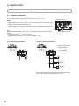
9. CONNECTIONS
External cable wiring must be only carried out by qualified and trained personnel.
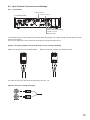
9.1. Speaker Connection
For cable wiring to the removable terminal block, refer to p. 18.
Notes
• Never make connection to both 4 Ω (low impedance) and 70 V line (high
impedance) terminals simultaneously.
• Never make connection to 4 Ω terminal when the Impedance setting switch
is set to 70 V.
Tip
Recommended speaker cable is IV or HIV cable with thickness described
below.
Solid copper cable: ø0.32 – 2.0 mm
Stranded copper cable: 0.05 – 3.3 mm
2
(AWG 30 – 12)
[Low impedance connection]
Speaker output terminal
A-812D/824D/848D
4 to 16 Ω
[High impedance connection]
Combined impedance:
42 Ω (A-812D)
21 Ω (A-824D)
10 Ω (A-848D)
70 V line
70 V line
70 V line
For the audio output at high impedance application setting,
refer to "32. Speaker output terminal" on p. 11.

13
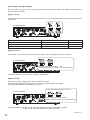
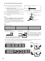
9.2. Input Terminal Connections and Settings
9.2.1. Connections
The terminal used for each of the Inputs 5 and 6 differs depending on the Input setting switches (input 5 and 6).
(See the next page.)
Connect the cable to the correct terminal according to the input terminal to use.
[Inputs 1 through 6 (Inputs 5 and 6 connections are for routing to AUDIO)]
(When connecting a 2-core shielded cable)
For cable wiring to the removable terminal plug, refer to p. 18.
[Inputs 5 and 6 (for routing to DUCK)]
(When connecting a single core shielded cable)
Inputs 3 and 4
Inputs 1 and 2
Inputs 5 and 6
Removable terminal block
Inputs 5 and 6
RCA Pin jack
A-812D/824D/848D

14
9.2.2. Inputs 1 through 6 settings
Each of Inputs 1 through 6 has its own setting switch corresponding to each input. Perform their settings as
shown below as needed.
[Inputs 1 and 2]
Set the sound source level to connect and whether or not to use the phantom power when the microphone input
is selected.
A-812D/824D/848D
Input sound source Switch position Input specication
Line level LINE –20 dB*, 600 Ω
Microphone level, phantom power not required MIC – PHANTOM OFF (Factory-preset) –60 dB*, 600 Ω
Microphone level, phantom power required MIC – PHANTOM ON –60 dB*, 600 Ω
[Inputs 3 and 4]
Set whether or not to use phantom power on the Inputs 3 and 4 (dedicated microphone inputs).
Phantom power when needed: ON
Phantom power when not needed: OFF (Factory-preset)
A-812D/824D/848D
Input specications: –60 dB*, 600 Ω, electronically balanced
[Inputs 5 and 6]
Set which to send the input audio signals to AUDIO or DUCK.
Operation when the Ducker function works is different between AUDIO and DUCK.
(See "DUCKER DEPTH ADJUSTMENT" on p. 20.)
[Input setting switches (Inputs 5 and 6)]
When sending to AUDIO: AUDIO
When sending to DUCK: DUCK (Factory-preset)
A-812D/824D/848D
Input specications: –60 dB*, 600 Ω, electronically balanced (when outputting to AUDIO)
–20 dB*, 10 kΩ, unbalanced (when outputting to DUCK)
* 0 dB = 1 V

15
9.3. Connecting to the Remote Master Volume Control Terminal
You can remotely control the unit’s volume level by connecting a volume controller.
To remotely control the volume level, adjust the unit’s volume level with the master volume control knob in
advance. The level adjusted with the master volume control knob is the maximum volume level that you can
remotely control.
For cable wiring to the removable terminal plug, refer to p. 18.
Note
Never set the master volume control knob to the minimum position. If set to the minimum, no sound is output
even if you maximize the volume level through this terminal.
(See "VOLUME ADJUSTMENT" on p. 20.)
A-812D/824D/848D
Connectable volume controller: 10 kΩ B-taper potentiometer
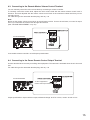
9.4. Connecting to the Power Remote Control Output Terminal
Use this terminal when remotely controlling other equipment. This terminal is activated when the unit is turned
ON.
For cable wiring to the removable terminal plug, refer to p. 18.
To other equipment’s
remote control input terminal
A-812D/824D/848D
Output specications: Open collector output, withstand voltage: 30 V DC or less, current: 25 mA or less

16
9.5. Connecting to the Emergency Control Output Terminal
Use this terminal when remotely controlling other equipment. This terminal is activated while the emergency
broadcast is in progress from this unit.
For cable wiring to the removable terminal plug, refer to p. 18.
To other equipment’s
remote control input terminal
A-812D/824D/848D
Output specications: Open collector output, withstand voltage: 30 V DC or less, current: 25 mA or less
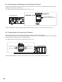
9.6. Connecting to the Control Input Terminal
Priority broadcast can be controlled by inputting the contact signal to these terminals.
For the priority setting, refer to the separate setup manual, which can be downloaded from the TOA DATA
Library (https://www.toa-products.com/international/).
For cable wiring to the removable terminal plug, refer to p. 18.
Input signal specications: Short-circuit current: 10 mA or less, open voltage: 35 V DC or less
Control input 2 Control input 1
Control input 3
Control input 4
A-812D/824D/848D

17
9.7. Connecting the External Equipment between the Pre-amplifier Output and the Power
Amplifier
Appropriate sound can be obtained by connecting a signal processor like an equalizer or limiter between the
unit’s preamplier section (Pre-amplier output jack) and the power amplier section (Power amplier input
jack).
Note
Inserting a pin plug into the unit’s power amplier input jack disconnects the preamplier section from the power
amplier section inside the unit.
IN
OUT
Signal processor
A-812D/824D/848D
Pre-amplier output specications: 0 dB*, 600 Ω, unbalanced
Power amplier input specications: 0 dB*, 600 Ω, unbalanced
* 0 dB = 1 V

18
9.8. Removable Terminal Plug Connection
Step 1. Wiring the supplied removable terminal plug.
1-1. Loosen the terminal screws to insert the wire.
1-2. Tighten the terminal screws.
Ensure that the wire does not break free when
pulled. If the wire does pull free, repeat the
connection procedure from the start.
Step 2. Insert the wired terminal plug into the corresponding
terminal block in the unit’s rear panel.
Step 3. Only when the xing screw is inserted, tighten the
xing screw.
Notes
• Do not reverse Steps 1 and 2 above. Poor contact may
result if force is applied to the unit’s internal circuit board
pins while the terminal screws are being tightened.
• When detaching the terminal plug, pull it straight out. Pulling
it out at an angle may cause the terminal plug or terminal
block to break.
Slotted screwdriver
LoosensTightens
Removable terminal plug
(accessory)
Terminal screw
Fixing screw
1
[Recommended type of screwdriver ]
Blade width*
1
*
1
For speaker output terminal: About 3.5 mm (0.14")
For other terminals: About 2.5 mm (0.1")
Tips
• Applicable cable size
For speaker output terminal For other terminals
Conductor cross-section area 0.05 − 3.3 mm
2
0.08 − 2.0 mm
2
AWG AWG 30 − 12 or equivalent AWG 28 − 14 or equivalent
Solid cable and stranded cable Shielded cable
7 mm*
2
7 mm*
2
20 mm
(0.28'') (0.28'')
(0.79'')
*
2
Expose 8 mm (0.31") or more when using
the above ferrule terminal, and cut off an
extra conductor protruding from the sleeve.
Note
Avoid soldering stranded or shielded
cable, as contact resistance may increase
when the cable is tightened and the
solder is crushed, possibly resulting in an
excessive rise in joint temperatures.
• When connecting 2 cables or a shielded cable to a single terminal, use a ferrule terminal with an insulation
sleeve to crimp the cables because such cable conductors could become loose.
(1) Recommended ferrule terminals for signal cables
(made by Phoenix Contact)
Model Number a l
1
l
2
AI 0,34-8 TQ
AI 0,5-8 WH
2 (0.08)
Unit: mm (in)
2.5 (0.1)
12.5 (0.49)
14 (0.55)
8 (0.31)
8 (0.31)
b
0.8 (0.03)
1.1 (0.04)
(2) Recommended ferrule terminals for speaker cables
(made by Phoenix Contact)
Model Number a
1
l
1
l
2
AI 1,5-8 BK
AI-TWIN 2x1,5-8 BK
6.6 (0.26)
a
2
3.6 (0.14)
14 (0.55)
16 (0.63)2.3 (0.09)
8 (0.31)
8 (0.31)
a
3.4 (0.31)
Unit: mm (in)
b
1.8 (0.07)
Crimping tool: CRIMPFOX 10S (made by Phoenix Contact)
Insulation sleeve
Contact section
Insulation sleeve
Contact section
a
l
2
a
1
a
2
l
1
l
2
l
1
bb
• Cable sheath to trim

19
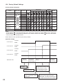
10. SETTINGS
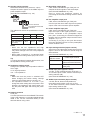
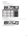
10.1. Chime Tone Setting
Set the chime tone to use with the DIP switches 1 and 2.
A-812D/824D/848D
Chime tone to use Switch 1 Switch 2 Switch’s gures
4-note
(Factory-preset)
OFF OFF
1 2 3 4 5 6
OFF
ON
2-note ON OFF
1 2 3 4 5 6
OFF
ON
1-note OFF ON
1 2 3 4 5 6
OFF
ON
Not used ON ON
1 2 3 4 5 6
OFF
ON
10.2. Module Setting
Set which to send the output from the module input to the AUDIO or DUCK using Switches 3 and 4 of the DIP
switch. (See "BLOCK DIAGRAM" on p. 26.)
A-812D/824D/848D
OFF: Output from the module input is sent to the DUCK.
ON: Output from the module input is sent to the AUDIO.

20
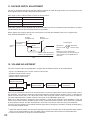
11. DUCKER DEPTH ADJUSTMENT
The unit is equipped with Ducker function. When broadcast is made through AUDIO, the volume level of the
audio signals input to DUCK is automatically attenuated.
Each input is sent to either AUDIO or DUCK as shown below.
Input No. Input destination
Inputs 1 through 4 AUDIO
Inputs 5 and 6 AUDIO or DUCK selectable
Modules 1 and 2 AUDIO or DUCK selectable
Attenuation amount can be adjusted with the Ducker depth control knob. Rotate the knob clockwise to increase
the attenuation amount and counterclockwise to decrease it.
When signals stop entering AUDIO, the volume level on DUCK automatically returns to its original level.
(See "BLOCK DIAGRAM" on p. 26.)
AUDIO
broadcast start
AUDIO
broadcast end
DUCK broadcast
in progress
Volume
level
Attenuation amount
Small
Large
DUCK volume level slowly
returns to its original level.
Time
Attenuation
amount: small
Attenuation
amount: large
Ducker depth
Note
When the knob is rotated fully
counterclockwise, the volume level of
audio signals such as BGM will not
decrease.
12. VOLUME ADJUSTMENT
The unit’s volume value can be adjusted in 4 steps with the different means as described below.
• Inputs 1 to 6/Module inputs 1 and 2 volume control knobs
• Software master volume control
• Remote master volume control
• Master volume control knob
Master volume
control knob
Remote master
volume control
Software master
volume control
Input 1
Volume control knob
Module input 2
Volume control knob
If any one of the volume controls is set to the minimum, no sound is output even if other volume control is set to
the maximum. If you intend to adjust the volume value with the Software master volume control*
1
or the Remote
master volume control (see p. 15), adjust the volume value using the master volume control knob in advance.
The value adjusted with the master volume control knob is the adjustable upper limit.
When set to the Emergency broadcast, the broadcast is made at the maximum level regardless of the set
values of the master volume, software master volume, and remote master volume*
2
. Also, the chime is sounded
at the maximum volume, and the characteristics of the EQ, tone control, and bass control are made flat.
The front-mounted emergency broadcast indicator lights during emergency broadcast, making the Emergency
control output terminal closed.
*
1
Adjust the Software master volume control using the browser. For details, refer to the separate setup manual,
which can be downloaded from the TOA DATA Library (https://www.toa-products.com/international/).
*
2
Volume control knobs for each input remain effective.
La page est en cours de chargement...
La page est en cours de chargement...
La page est en cours de chargement...
La page est en cours de chargement...
La page est en cours de chargement...
La page est en cours de chargement...
La page est en cours de chargement...
La page est en cours de chargement...
-
 1
1
-
 2
2
-
 3
3
-
 4
4
-
 5
5
-
 6
6
-
 7
7
-
 8
8
-
 9
9
-
 10
10
-
 11
11
-
 12
12
-
 13
13
-
 14
14
-
 15
15
-
 16
16
-
 17
17
-
 18
18
-
 19
19
-
 20
20
-
 21
21
-
 22
22
-
 23
23
-
 24
24
-
 25
25
-
 26
26
-
 27
27
-
 28
28


TOA A-800D Series Digital Mixer/Amplifier Manuel utilisateur
- Catégorie
- Matériel musical
- Taper
- Manuel utilisateur
dans d''autres langues
Documents connexes
-
TOA D-2000AD1 Manuel utilisateur
-
-
Optimus A-5006 Manuel utilisateur
-
-
-
-
Optimus A-1812ER Fiche technique
-
-
-
TOA BG-2480D Manuel utilisateur
Autres documents
-
-
Yamaha MA2030 Le manuel du propriétaire
-
Yamaha MV800 Manuel utilisateur
-
-
-
-
Yamaha MGP16X/MGP12X Manuel utilisateur
-
Yamaha MGP32X Manuel utilisateur
-
-
Ecler HMA180 Manuel utilisateur