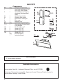
Faber CTAL31BK300B Guide d'installation
- Catégorie
- Hottes
- Taper
- Guide d'installation
Ce manuel convient également à

CTAL31BK300-B
CTAL36BK300-B
Installation Instructions
Use and Care Information
Instructions d'installation
Utilisez et d'entretien
COCKTAIL

2
READ AND SAVE THESE INSTRUCTIONS BEFORE YOU START
INSTALLING THIS RANGEHOOD
WARNING: - TO REDUCE THE RISK OF A RANGE TOP GREASE FIRE:
a) Never leave surface units unattended at high settings. Boilovers cause smoking and
greasy spillovers that may ignite. Heat oils slowly on low or medium setting.
b)AlwaysturnhoodONwhencookingathighheatorwhenambeingfood(i.e.Crepes
Suzette, Cherries Jubilee, Peppercorn Beef Flambé).
c) Clean ventilating fans frequently. Grease should not be allowed to accumulate on fan
orlter.
d) Use proper pan size. Always use cookware appropriate for the size of the surface element.
WARNING: - TO REDUCE THE RISK OF INJURY TO PERSONS IN THE EVENT OF A
RANGE TOP GREASE FIRE, OBSERVE THE FOLLOWING*:
a)SMOTHERFLAMESwithaclose-ttinglid,cookiesheet,ormetaltray,thenturnofftheburner.
BECAREFULTOPREVENTBURNS.IftheamesdonotgooutimmediatelyEVACUATE
AND CALL THE FIRE DEPARTMENT.
b) NEVER PICK UP A FLAMING PAN - You may be burned.
c) DO NOT USE WATER, including wet dishcloths or towels - a violent steam explosion will
result.
d) Use an extinguisher ONLY if:
1. You know you have a Class ABC extinguisher, and you already know how to operate it.
2. Thereissmallandcontainedintheareawhereitstarted.
3. Theredepartmentisbeingcalled.
4. Youcanghttherewithyourbacktoanexit.
* Based on "Kitchen Firesafety Tips" published by NFPA
WARNING - TO REDUCE THE RISK OF FIRE OR ELECTRIC SHOCK, do not use this
fan with any solid-state speed control device.
WARNING - TO REDUCE THE RISK OF FIRE, ELECTRICAL SHOCK, OR INJURY TO
PERSONS, OBSERVE THE FOLLOWING:
1. Use this unit only in the manner intended by the manufacturer. If you have any
questions, contact the manufacturer.
2. Before servicing or cleaning unit, switch power off at service panel and lock the
service disconnecting means to prevent power from being switched on acciden-
tally. When the service disconnecting means cannot be locked, securely fasten a
prominent warning device, such as a tag, to the service panel.
CAUTION: For General Ventilating Use Only. Do Not Use To Exhaust Hazardous or
Explosive Materials and Vapors.
WARNING - TO REDUCE THE RISK OF FIRE, ELECTRICAL SHOCK, OR INJURY TO
PERSONS, OBSERVE THE FOLLOWING:
1. InstallationWorkAndElectricalWiringMustBeDoneByQualiedPerson(s)InAccor-
dance With All Applicable Codes And Standards, Including Fire-Rated Construction.
2. Sufcientairisneededforpropercombustionandexhaustingofgasesthrough
theue(chimney)offuelburningequipmenttopreventbackdrafting.Followthe
heating equipment manufacturer's guideline and safety standards such as those
publishedbytheNational FireProtectionAssociation(NFPA),andtheAmerican
SocietyforHeating,RefrigerationandAirConditioningEngineers(ASHRAE),and
the local code authorities.

3
ALL WALL AND FLOOR OPENINGS WHERE THE RANGEHOOD IS INSTALLED MUST
BE SEALED.
This rangehood requires at least 24" of clearance between the bottom of the rangehood
and the cooking surface or countertop. This hood has been approved by UL at this distance from
the cooktop. Overhead cabinets on both sides of this unit must be a minimum of 18" above the
cooking surface or countertop. Consult the cooktop or range installation instructions given by
the manufacturer before making any cutouts. MOBILE HOME INSTALLATION The installation
of this rangehood must conform to the Manufactured Home Construction and Safety Standards,
Title 24 CFR, Part 3280 (formerly Federal Standard for Mobile Home Construction and Safety, Title
24, HUD, Part 280). See Electrical Requirements.
• Venting system MUST terminate outside the home.
• DO NOT terminate the ductwork in an attic or other enclosed space.
• DO NOT use 4" laundry-type wall caps.
• Flexible-type ductwork is not recommended.
• DO NOT obstruct the ow of combustion and ventilation air.
• Failure to follow venting requirements may result in a re.
WARNING
!
Cold Weather installations
An additional back draft damper should be installed to minimize backward cold air ow and a
nonmetallic thermal break should be installed to minimize conduction of outside temperatures as
part of the vent system. The damper should be on the cold air side of the thermal break. The break
should be as close as possible to where the vent system enters the heated portion of the house.
VENTING REQUIREMENTS
Determine which venting method is best for your application. Ductwork can extend either through the
wall or the roof.
The length of the ductwork and the number of elbows should be kept to a minimum to provide efcient
performance. The size of the ductwork should be uniform. Do not install two elbows together. Use
duct tape to seal all joints in the ductwork system. Use caulking to seal exterior wall or oor opening
around the cap.
Flexible ductwork is not recommended. Flexible ductwork creates back pressure and air turbulence
that greatly reduces performance.
Make sure there is proper clearance within the wall or oor for exhaust duct before making cutouts.
Do not cut a joist or stud unless absolutely necessary. If a joist or stud must be cut, then a supporting
frame must be constructed.
WARNING - To Reduce The Risk Of Fire, Use Only Metal Ductwork.
CAUTION-Toreduceriskofreandtoproperlyexhaustair,besuretoductairoutside–Do
not vent exhaust air into spaces within walls or ceilings or into attics, crawl spaces, or garages.
3. When cutting or drilling into wall or ceiling, do not damage electrical wiring and
other hidden utilities.
4. Ducted fans must always be vented to the outdoors.

4
ELECTRICAL REQUIREMENTS
A 120 volt, 60 Hz AC-only electrical supply is required on a separate 15 amp fused circuit. A time-delay
fuse or circuit breaker is recommended. The fuse must be sized per local codes in accordance with
the electrical rating of this unit as specied on the serial/rating plate located inside the unit near the eld
wiring compartment.
ELECTRICAL INSTALLATION WITH WIRING BOX
THIS UNIT MUST BE CONNECTED WITH COPPER WIRE ONLY. Wire sizes must conform to the
requirements of the National Electrical Code, ANSI/NFPA 70 - latest edition, and all local codes and
ordinances. Wire size and connections must conform with the rating of the appliance. Copies of the
standard listed above may be obtained from:
National Fire Protection Association
Batterymarch Park
Quincy, Massachusetts 02269
This appliance should be connected directly to the fused disconnect (or circuit breaker) through
exible, armored or nonmetallic sheathed copper cable. Allow some slack in the cable so the
appliance can be moved if servicing is ever necessary. A UL Listed, 1/2" conduit connector must
be provided at each end of the power supply cable (at the appliance and at the junction box).
When making the electrical connection, cut a 1 1/4" hole in the wall. A hole cut through wood
must be sanded until smooth. A hole through metal must have a grommet.
• Electrical ground is required on this rangehood.
• If cold water pipe is interrupted by plastic, nonmetallic gaskets or other materials, DO
NOT use for grounding.
• DO NOT ground to a gas pipe.
• DO NOT have a fuse in the neutral or grounding circuit. A fuse in the neutral or
grounding circuit could result in electrical shock.
• Check with a qualied electrician if you are in doubt as to whether the rangehood is
properly grounded.
• Failure to follow electrical requirements may result in a re.
WARNING
!

5
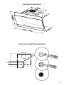
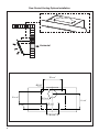
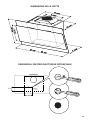
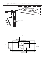
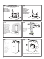
RANGEHOOD DIMENSIONS
ELECTRICAL CONNECTION KNOCKOUT
´
´
´

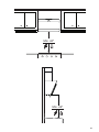
6
Min. 21 3/16"
Min. 24"

7
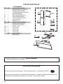
MAIN PARTS
Components
Ref. Qty. Product Components
1 1 Hood Body, complete with: Con-
trols, Light, Filters, Blower.
2 1 Optional Telescopic Chimney
comprising (Purchased Sepa
rately):
2.1 1 Optional Upper Section
2.2 1 Optional Lower Section
3 1 Directional Air Outlet grille
4 1 Filter cover
10 1 Damper ø 5 7/8"
Ref. Qty. Installation Components
7.2.1 2 Optional Upper Chimney Section
Fixing Brackets
12a 4 Screws 3/16" x 1 3/4"
12b 2 Screws 1/8" x 3/8"
12c 4 Screws 1/8" x 1/4"
12d 2 Screws 1/8" x 3/8"
12e 4 Screws 1/8" x 1/4"
Qty. Documentation
1 Instruction Manual
Available Accessories
Recirculation Vent Kit - Activated Charcoal Filter - sku # FILTER1
Telescopic Chimney Accessory Kit - Upper and Lower Chimney Flue for Ducted or
Recirculation Venting - sku# CHIM1
Parts needed
- 6" Round Metal ductwork .
2.2
2.1
10
7.2.1
12b
12a
12c
1
12d
12e
4
3

8
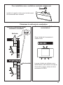
Choose your ducting method
Non Ducted - Recirculation OptionDucted Venting Options Installation
Requires purchase of Activated
Charcoal Accessory
Horizontal
Vertical
6"
H
I
Install Damper that is included with the Hood
before connecting to the ductwork.
Only for Ducted Venting Installation
When used in recirculation mode,
To Reduce the Risk of Fire and
Shock use only conversion kit Model
FILTER1

9
Rear Ducted Venting Options Installation
Horizontal
´
´
´
´
´
´
´
´

10
8x
8x
A1
A3
A4 A5
A2
a
2x
b
Rear Ducted Venting Options Installation
8x
8x
A1
A3
A4 A5
A2
a
2x
b
8x
8x
A1
A3
A4 A5
A2
a
2x
b
8x
8x
A1
A3
A4 A5
A2
a
2x
b
8x
8x
A1
A3
A4 A5
A2
a
2x
b
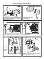
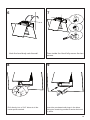
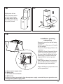
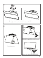
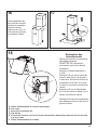
Remove the four screws from each cover plate as
shown and take off the cover plates. Do not discard
and set aside for future use.
Disconnect the Connector
from the blower
Unscrew the 2 screws that hold the blower and unlock it from the initial position.
Carefully
fold out the
4 tabs on
the sides of
the hole.
Re-attach the two plates that were removed using
the 8 screws as shown above.
8x
8x
A1
A3
A4 A5
A2
a
2x
b

11
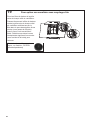
A6
A8
A7
a
b
2x
A9
H=2x
A10
H=2x
Rear Ducted Venting Options Installation
A6
A8
A7
a
b
2x
A9
H=2x
A10
H=2x
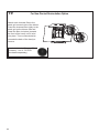
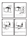
After removing blower rotate as shown
until it is in the correct rear venting position.
Use the two screws that were removed to
secure the blower as shown in Image B.
Reconnect the Connector.

12
1
2
Ø 5/16”
13 1/4”
5
1/8
”
u
u
x2
x2
5
1/8
”
x2
x2
´
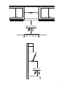
Draw a vertical line on the supporting wall as high as practical, at the center of the area in which
the hood will be installed.
Draw a horizontal line at where the bottom edge of the hood will be located as indicated in the gure
that is a minimum of 24" above cooking surface.
Mark the wall where indicated, 13 1/4" above the horizontal line and at 6 7/16" distance on the left
and right of vertical line. Checking that the two marks are level.
Insert two wall plugs (purchased separately) and two screws into the holes as shown.
Installation Instructions
Cooker Hood Installation

13
4 5
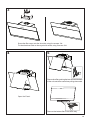
Open the Panel.
Remove the lter, pushing the lever towards the back
of the unit and at the same time pulling downward.
3
Screw the lter cover onto the air outlet, using four screws 12e.
Fix the directional Grid on the recycled air outlet, using 2 screws 12d.
Remove the bottom lter in the same way.

14
Insert the purchased wall plugs in the holes.
Using two remaining screws to anchor the hood
in holes.
5/16 "
8 9
Drill directly into ø 5/16" holes at all the
center points marked.
6
Hook the hood body onto the wall. From inside the Hood fully secure the two
screws.
7

15
x2
x4
x4
Ø
1/2”
´
>
´
13
1/4
”
u
u
x2
x2
x2
´
5
1/8
”
5
1/8
”
Mark the wall where indicated, 13 1/4" above the horizontal line and at 6 7/16" distance on the left
and right of vertical line. Checking that the two marks are level.
Insert two wall plugs (purchased separately) and two screws into the holes as shown.
Place a bracket 7.2.1 on the wall as shown about 1 1/8" from the ceiling or upper limit, aligning the
center (notch) with the vertical reference line and mark the wall at the centers of the holes in the bracket.
Place the second bracket 7.2.1 on the wall as shown, below the rst bracket, at the height of the
upper chimney section supplied and aligning the center (notch) with the vertical line.
Mark the wall at the centers of the holes in the bracket and drill ø 5/16" as shown.
Installation screws provided for the Brackets, must be secured with wall plugs (purchased separately).
Cooker Hood Installation with optional Chimney
2.2
2.1
2.1
2.1

16
11
12
13
10
Vertical or Horizontal
Ducting Installation
Fix the bracket
7.2.1 using the
screws 12a
supplied.
L = 4x
12a
If installed,
unfasten the four
screws as shown
and remove lter
cover.
Use the four
screws removed
previously to
secure the angle
bracket included
with Optional Tele-
scopic Chimney
Kit.
Install Roof or Wall
Cap purchased
separately. Con-
nect the 6" metal
ductwork to the
Roof or Wall Cap
and then attach
ductwork.
14
Slightly widen
the two sides
of the upper
chimney and
hook them
behind the
brackets 7.2.1,
making sure
that they are
well seated.
Secure the sides to the brackets by using the 4
screws 12b.
15
N = 4x
2.1

17
2.1
16
Slightly widen the two
sides of the lower section
and hook them between
the upper section and the
wall, making sure that they
are properly housed.
17
N = 2x
18
2.1
2.2
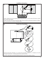
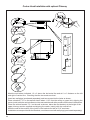
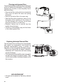
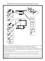
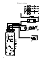
A. Home power supply cable
B. Black wires
C. UL listed wire connectors
D. White wires
E. Green (or bare) ground wire from home power supply connected to green ground screw
F. Range hood power supply cable
Installation of wiring
connection
Remove the cover from the eld wiring
compartment.
DO NOT turn on the power until installa-
tion is complete!
Connect the Power Supply Cable to the
rangehood.
Connect the Green (Green and Yellow)
ground wire under the Green ground-
ing screw. Attach the White lead of the
power supply to the White lead of the
rangehood with a twist-on type wire
connector.
Attach the Black lead of the power sup-
ply to the Black lead of the rangehood
with a twist-on type wire connector.
Replace the eld wiring compartment cover
and the grease lters.
E
A
F
D
C
B

18
19
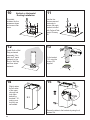
For Non-Ducted Recirculation Option
Required Activated Charcoal Filter
Accessory - sku # - FILTER1
(purchased separately)
Attach each charcoal lter to the
black grid on each side of the blower.
Press the charcoal lter tightly to the
black grid on the blower side and
rotate the lter clockwise (towards
the front of the hood) until it locks
into place. Turn counterclockwise
(towards the back of the hood) to
remove.

19
USE AND CARE INFORMATION
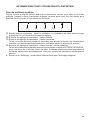
T1. Fan Off Button:Turn the blower Off. The fan can be operated by pressing any of the fan setting
buttons.
T2. Fan Settings Buttons: Low Speed.
T3. Fan Settings Buttons: Medium Speed.
Hold down this button for 2 seconds to activate Delay Off function which will keep the fan On for 30
minutes and automatically shut Off
T4. Fan Settings Buttons: High Speed / Intensive Speed.
Hold down the button for 2 seconds to activate the INTENSIVE SPEED, which is timed to run for 6
minutes. At the end of this time it will automatically return to the speed set before.Suitable to deal
with maximum levels of cooking fumes.
L. Light Button: On/Off switch for the halogen lights.
LT1 T2 T3 T4
For Best Results
Start the rangehood several minutes before cooking to develop proper airow. Allow the
rangehood to operate for several minutes after cooking is complete to clear all smoke and
odors from the kitchen.

20
LED LIGHTING UNIT
• LED lights must be replaced by Faber factory authorized
service.
Cleaningmetalgreaselters
The metal grease lters can be cleaned in hot detergent
solution or washed in the dishwasher. They should be
cleaned every 2 months, or more frequently if use is
particularly heavy.
• Remove the lter, pushing the lever towards the
back of the unit and at the same time pulling
downward.
• Remove the bottom lter in the same way.
• Wash the lter without bending it, leave it to dry
thoroughly before replacing (if the surface of
the lter changes color over time, this will have
absolutely no effect on its efciency).
• Replace, taking care to ensure that the
handle faces forward.
• Cleaning in dishwasher may dull the nish
of the metal grease lter.
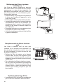
Replacing Activated Charcoal Filter
The Activated Charcoal Filters are not washable
and cannot be regenerated, and should be
replaced approximately every 4 months of
operation, or more frequently with heavy usage.
• Remove the charcoal lter by rotating it clockwise (
backwards) until it unlocks from the motor housing
and pull off sideways.
• To re-insert each charcoal lter, place up against
the side of the blower and push it inward. Then
turn the charcoal lter clockwise (forward) until it
ts into place.
La page est en cours de chargement...
La page est en cours de chargement...
La page est en cours de chargement...
La page est en cours de chargement...
La page est en cours de chargement...
La page est en cours de chargement...
La page est en cours de chargement...
La page est en cours de chargement...
La page est en cours de chargement...
La page est en cours de chargement...
La page est en cours de chargement...
La page est en cours de chargement...
La page est en cours de chargement...
La page est en cours de chargement...
La page est en cours de chargement...
La page est en cours de chargement...
La page est en cours de chargement...
La page est en cours de chargement...
La page est en cours de chargement...
La page est en cours de chargement...
La page est en cours de chargement...
La page est en cours de chargement...
La page est en cours de chargement...
La page est en cours de chargement...
-
 1
1
-
 2
2
-
 3
3
-
 4
4
-
 5
5
-
 6
6
-
 7
7
-
 8
8
-
 9
9
-
 10
10
-
 11
11
-
 12
12
-
 13
13
-
 14
14
-
 15
15
-
 16
16
-
 17
17
-
 18
18
-
 19
19
-
 20
20
-
 21
21
-
 22
22
-
 23
23
-
 24
24
-
 25
25
-
 26
26
-
 27
27
-
 28
28
-
 29
29
-
 30
30
-
 31
31
-
 32
32
-
 33
33
-
 34
34
-
 35
35
-
 36
36
-
 37
37
-
 38
38
-
 39
39
-
 40
40
-
 41
41
-
 42
42
-
 43
43
-
 44
44


Faber CTAL31BK300B Guide d'installation
- Catégorie
- Hottes
- Taper
- Guide d'installation
- Ce manuel convient également à
dans d''autres langues
Documents connexes
-
Faber Nova Pro 30 SSV with VAM Guide d'installation
-
-
-
-
-
-
-
-
-